
Calculator for a Beam supported One End, Pin Opposite End and two Partial Distributed Load Separated
Calculating the reactions and stresses of a beam supported at one end with a pin at the opposite end and subjected to two partial distributed loads can be complex. This type of beam is commonly found in engineering structures, and its analysis is crucial for ensuring safety and efficiency. A calculator designed for this specific scenario can simplify the process, providing accurate results and saving time. The calculator takes into account the load's magnitude, position, and distribution, as well as the beam's length and material properties, to determine the support reactions and shear and moment diagrams.
- Calculator for a Beam Supported One End, Pin Opposite End and Two Partial Distributed Load Separated
- How to calculate simply supported beam?
- How do you calculate the stress of a beam?
- What is the formula for the deflection of a beam fixed at both ends?
- How do you calculate the deflection of a simple supported beam?
-
Frequently Asked Questions (FAQs)
- What is the purpose of the Calculator for a Beam supported One End, Pin Opposite End and two Partial Distributed Load Separated?
- How does the Calculator for a Beam supported One End, Pin Opposite End and two Partial Distributed Load Separated account for the partial distributed loads?
- What are the limitations and assumptions of the Calculator for a Beam supported One End, Pin Opposite End and two Partial Distributed Load Separated?
- How can the Calculator for a Beam supported One End, Pin Opposite End and two Partial Distributed Load Separated be used in real-world applications?
Calculator for a Beam Supported One End, Pin Opposite End and Two Partial Distributed Load Separated
The calculator for a beam supported one end, pin opposite end and two partial distributed load separated is a .review tool used to determine the reactions, shear force, and bending moment diagrams for a beam with a specific set of boundary conditions. This calculator is particularly useful for engineers and designers who need to analyze and design beams with complex loading conditions.
Introduction to Beam Calculators
Beam calculators are software tools that help engineers and designers analyze and design beams with various boundary conditions and loading conditions. These calculators can be used to determine the reactions, shear force, and bending moment diagrams for a beam, as well as the stress and strain at specific points along the beam. The calculator for a beam supported one end, pin opposite end and two partial distributed load separated is a specific type of beam calculator that is designed to handle a particular set of boundary conditions.
Boundary Conditions for the Calculator
The boundary conditions for the calculator for a beam supported one end, pin opposite end and two partial distributed load separated are as follows:
- One end of the beam is simply supported, meaning that it is free to rotate but not to translate.
- The opposite end of the beam is pinned, meaning that it is fixed in place and cannot rotate or translate.
- There are two partial distributed loads applied to the beam, each with a specific magnitude and location.
The calculator can handle these boundary conditions and provide the reactions, shear force, and bending moment diagrams for the beam.
Reactions, Shear Force, and Bending Moment Diagrams
The calculator for a beam supported one end, pin opposite end and two partial distributed load separated can be used to determine the reactions, shear force, and bending moment diagrams for the beam. These diagrams are important tools for engineers and designers, as they provide a visual representation of the internal forces and moments acting on the beam. The reactions diagram shows the forces acting on the beam at the supports, while the shear force diagram shows the shear force acting on the beam at each point along its length. The bending moment diagram shows the bending moment acting on the beam at each point along its length.
Applications of the Calculator
The calculator for a beam supported one end, pin opposite end and two partial distributed load separated has a wide range of applications in engineering and design. It can be used to analyze and design beams with complex loading conditions, such as those found in bridges, buildings, and machines. The calculator can also be used to optimize the design of a beam, by adjusting the boundary conditions and loading conditions to minimize the stress and strain on the beam.
Example Problem
The following is an example problem that can be solved using the calculator for a beam supported one end, pin opposite end and two partial distributed load separated:
| Parameter | Value |
|---|---|
| Length of beam | 10 m |
| Partial distributed load 1 | 5 kN/m |
| Partial distributed load 2 | 3 kN/m |
| Location of partial distributed load 1 | 2 m from simply supported end |
| Location of partial distributed load 2 | 6 m from simply supported end |
Using the calculator, the reactions, shear force, and bending moment diagrams can be determined for the beam, and the stress and strain at specific points along the beam can be calculated.
How to calculate simply supported beam?
To calculate a simply supported beam, we need to understand the loads and reactions acting on the beam. The beam is a horizontal structural element that carries loads from any direction, and the supports at the ends of the beam provide reactions to balance the loads. We can calculate the reactions at the supports using the equilibrium equations, which state that the sum of all forces and moments acting on the beam must be equal to zero.
Understanding Beam Reactions
To calculate the reactions at the supports, we need to consider the types of loads acting on the beam, such as point loads, uniformly distributed loads, and moments. The reactions at the supports can be calculated using the following steps:
- Draw a free body diagram of the beam to visualize the loads and reactions.
- Apply the equilibrium equations to calculate the reactions at the supports.
- Use the principle of superposition to calculate the reactions due to each load acting on the beam.
Calculating Beam Moments
The moments acting on the beam can be calculated using the moment diagram, which shows the variation of moments along the length of the beam. To calculate the moments, we need to consider the bending moment and the torsional moment. The bending moment can be calculated using the following formula: M = (P x), where M is the bending moment, P is the point load, and x is the distance from the support to the point of interest. The torsional moment can be calculated using the following formula: T = (M r), where T is the torsional moment, M is the bending moment, and r is the radius of gyration.
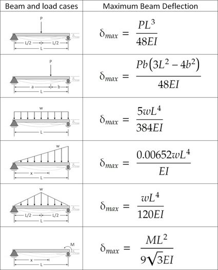
Beam Deflection and Slope
The deflection and slope of the beam can be calculated using the deflection formula: y = (P x^3) / (3 E I), where y is the deflection, P is the point load, x is the distance from the support to the point of interest, E is the modulus of elasticity, and I is the moment of inertia. The slope of the beam can be calculated using the following formula: dy/dx = (P x^2) / (2 E I).
Beam Stress and Strain
The stress and strain acting on the beam can be calculated using the stress formula: σ = (M y) / I, where σ is the stress, M is the bending moment, y is the distance from the neutral axis to the point of interest, and I is the moment of inertia. The strain can be calculated using the following formula: ε = (σ / E), where ε is the strain, σ is the stress, and E is the modulus of elasticity.
Designing a Simply Supported Beam
To design a simply supported beam, we need to consider the design requirements, such as the load capacity, deflection, and stress. We can use the following steps to design a simply supported beam:
- Determine the load capacity of the beam using the ultimate strength and factor of safety.
- Calculate the deflection and slope of the beam using the deflection formula and slope formula.
- Calculate the stress and strain acting on the beam using the stress formula and strain formula.
How do you calculate the stress of a beam?

To calculate the stress of a beam, you need to consider the forces acting on it, such as bending, tension, and compression. The stress calculation involves determining the moment of the force applied to the beam, as well as the cross-sectional area and moment of inertia of the beam. The stress is then calculated using the formula: stress = (moment distance) / (moment of inertia cross-sectional area).
Understanding Beam Stress Calculation
The calculation of beam stress requires a thorough understanding of the mechanics of materials. To calculate the stress, you need to determine the type of loading applied to the beam, such as point loading, uniformly distributed loading, or moment loading. The stress calculation also depends on the beam's material properties, such as its modulus of elasticity and Poisson's ratio.
- Determine the type of loading applied to the beam
- Calculate the moment of the force applied to the beam
- Determine the cross-sectional area and moment of inertia of the beam
Types of Beam Stress
There are several types of beam stress, including bending stress, tensile stress, and compressive stress. Bending stress occurs when a beam is subjected to a bending moment, causing it to deflect. Tensile stress occurs when a beam is subjected to a tensile force, causing it to stretch. Compressive stress occurs when a beam is subjected to a compressive force, causing it to shorten.
- Bending stress: occurs due to bending moment
- Tensile stress: occurs due to tensile force
- Compressive stress: occurs due to compressive force
Importance of Beam Stress Calculation
The calculation of beam stress is crucial in engineering design to ensure that the beam can withstand the applied loads without failing. Beam stress calculation helps to determine the safe load that a beam can carry, and it also helps to optimize the beam's design to minimize weight and cost. The stress calculation also helps to predict the failure mode of the beam, such as yielding or buckling.
- Ensure the beam can withstand applied loads
- Determine the safe load that a beam can carry
- Optimize the beam's design to minimize weight and cost
Beam Stress Calculation Methods
There are several methods for calculating beam stress, including the simple beam theory, beam deflection theory, and finite element method. The simple beam theory assumes that the beam is straight and prismatic, and it uses the beam equation to calculate the stress. The beam deflection theory takes into account the deflection of the beam, and it uses the deflection equation to calculate the stress. The finite element method uses a numerical approach to calculate the stress by dividing the beam into small elements.
- Simple beam theory: assumes straight and prismatic beam
- Beam deflection theory: takes into account beam deflection
- Finite element method: uses numerical approach
Applications of Beam Stress Calculation
The calculation of beam stress has numerous applications in civil engineering, mechanical engineering, and aerospace engineering. It is used to design bridges, buildings, and aircraft structures, as well as machine components such as shafts and gears. The stress calculation helps to ensure that the structure or component can withstand the applied loads and stresses without failing.
- Design of bridges and buildings
- Design of aircraft structures
- Design of machine components such as shafts and gears
What is the formula for the deflection of a beam fixed at both ends?
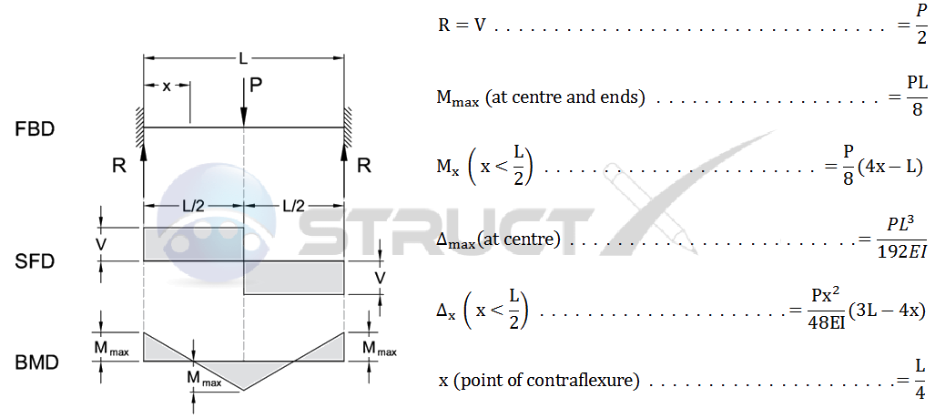
The formula for the deflection of a beam fixed at both ends is given by the equation: Δ = (W L^3) / (192 E I), where Δ is the deflection, W is the load, L is the length of the beam, E is the modulus of elasticity, and I is the moment of inertia. This formula is used to calculate the maximum deflection of a beam that is fixed at both ends and subjected to a uniform load.
Assumptions for the Formula
The formula for the deflection of a beam fixed at both ends is based on several assumptions, including:
- The beam is made of a homogeneous material with a constant cross-sectional area.
- The load is applied uniformly along the length of the beam.
- The beam is fixed at both ends, meaning that it is unable to rotate or translate at these points.
These assumptions are important to keep in mind when using the formula, as they can affect the accuracy of the results.
Key Factors in the Formula
The formula for the deflection of a beam fixed at both ends takes into account several key factors, including:
- The load (W) applied to the beam, which can be a point load or a uniformly distributed load.
- The length (L) of the beam, which affects the deflection of the beam.
- The moment of inertia (I) of the beam, which is a measure of the beam's resistance to bending.
These key factors can have a significant impact on the deflection of the beam, and must be carefully considered when designing or analyzing a beam.
Types of Beams
There are several types of beams that can be analyzed using the formula, including:
- Simply supported beams, which are supported at both ends but are free to rotate.
- Cantilever beams, which are fixed at one end and free at the other.
- Fixed-fixed beams, which are fixed at both ends and are the subject of the formula.
Each type of beam has its own unique characteristics and deflection behavior, and the formula must be modified accordingly.
Applications of the Formula
The formula for the deflection of a beam fixed at both ends has a wide range of applications, including:
- Building design, where it is used to analyze the deflection of beams and columns.
- Bridge design, where it is used to analyze the deflection of bridge decks and superstructures.
- Machine design, where it is used to analyze the deflection of machine components such as shafts and gears.
The formula is an essential tool in these applications, as it allows engineers to design and analyze beams and other structures with confidence.
Limitations of the Formula
The formula for the deflection of a beam fixed at both ends has several limitations, including:
- Non-linear behavior, where the deflection of the beam is not directly proportional to the load.
- Material non-linearity, where the material properties of the beam change under load.
- Dynamic loading, where the load on the beam is changing over time.
These limitations must be carefully considered when using the formula, as they can affect the accuracy of the results and the safety of the structure. The deflection of a beam can be affected by many factors, including the load, length, and material properties, and the formula must be used in conjunction with other methods to ensure accurate results.
How do you calculate the deflection of a simple supported beam?
To calculate the deflection of a simple supported beam, you need to consider the beam's length, load, and support conditions. The deflection of a beam is the measure of how much it bends under a given load. The calculation involves using the beam's moment of inertia, Young's modulus, and the load distribution. The formula for the deflection of a simple supported beam is given by the beam deflection equation, which takes into account the load intensity, beam length, and support conditions.
Understanding Beam Deflection
The deflection of a beam is a critical parameter in structural analysis, as it affects the stability and integrity of the structure. To calculate the deflection, you need to understand the beam's geometry, material properties, and load conditions. The following steps are involved in calculating the deflection:
- Determine the beam's moment of inertia, which depends on the beam's cross-sectional area and shape.
- Calculate the load intensity, which is the force per unit length applied to the beam.
- Determine the support conditions, which can be either simply supported or fixed.
Beam Deflection Equations
The beam deflection equation is a fundamental concept in structural mechanics, which describes the relationship between the load, beam length, and deflection. The equation is given by the flexure formula, which is derived from the beam's moment of inertia and Young's modulus. The following are the key components of the beam deflection equation:
- The flexure formula, which relates the moment, curvature, and beam deflection.
- The beam's moment of inertia, which affects the beam's stiffness and deflection.
- The load distribution, which can be either uniform or concentrated.
Load Distribution and Deflection
The load distribution is a critical factor in determining the beam deflection, as it affects the moment and shear forces acting on the beam. The following are the key considerations for load distribution and deflection:
- The load intensity, which is the force per unit length applied to the beam.
- The load distribution, which can be either uniform, triangular, or concentrated.
- The beam's support conditions, which can be either simply supported or fixed.
Material Properties and Deflection
The material properties of the beam, such as Young's modulus and Poisson's ratio, play a significant role in determining the beam deflection. The following are the key considerations for material properties and deflection:
- The Young's modulus, which affects the beam's stiffness and deflection.
- The Poisson's ratio, which affects the beam's lateral strain and deflection.
- The beam's material density, which affects the beam's weight and deflection.
Support Conditions and Deflection
The support conditions of the beam, such as simply supported or fixed, significantly affect the beam deflection. The following are the key considerations for support conditions and deflection:
- The support conditions, which can be either simply supported, fixed, or pinned.
- The beam's end conditions, which can be either free, pinned, or fixed.
- The beam's intermediate supports, which can affect the beam's deflection and stability.
Frequently Asked Questions (FAQs)
What is the purpose of the Calculator for a Beam supported One End, Pin Opposite End and two Partial Distributed Load Separated?
The Calculator for a Beam supported One End, Pin Opposite End and two Partial Distributed Load Separated is a mathematical tool designed to calculate the bending moment, shear force, and deflection of a beam that is supported at one end and pinned at the opposite end, with two partial distributed loads separated by a certain distance. This calculator is useful for engineers and architects who need to design and analyze beams with complex loading conditions. The calculator takes into account the length of the beam, the magnitude and position of the distributed loads, and the boundary conditions at the supports. By using this calculator, users can quickly and accurately determine the stresses and strains on the beam, as well as its stability and safety.
How does the Calculator for a Beam supported One End, Pin Opposite End and two Partial Distributed Load Separated account for the partial distributed loads?
The Calculator for a Beam supported One End, Pin Opposite End and two Partial Distributed Load Separated accounts for the partial distributed loads by dividing the beam into segments and applying the load to each segment separately. The calculator uses the principle of superposition to combine the effects of each load on the beam, taking into account the position and magnitude of each load. The calculator also considers the length of each segment and the boundary conditions at the supports to ensure that the calculations are accurate and consistent. By using this approach, the calculator can handle complex loading conditions, including multiple loads and various load distributions. The calculator also provides visualizations of the bending moment, shear force, and deflection diagrams, making it easier for users to understand the behavior of the beam under different loading conditions.
What are the limitations and assumptions of the Calculator for a Beam supported One End, Pin Opposite End and two Partial Distributed Load Separated?
The Calculator for a Beam supported One End, Pin Opposite End and two Partial Distributed Load Separated is based on several assumptions and limitations. One of the main assumptions is that the beam is straight and prismatic, meaning that its cross-sectional area and moment of inertia are constant along its length. The calculator also assumes that the material of the beam is linearly elastic, meaning that it follows Hooke's law. Additionally, the calculator assumes that the loads are static and d Concurrent, meaning that they are applied slowly and do not change over time. The calculator also ignores the effects of friction, damping, and other external factors that may affect the behavior of the beam. Furthermore, the calculator is limited to two-dimensional analysis, meaning that it cannot handle three-dimensional problems or non-linear behavior. By understanding these limitations and assumptions, users can ensure that they are using the calculator correctly and interpreting the results accurately.
How can the Calculator for a Beam supported One End, Pin Opposite End and two Partial Distributed Load Separated be used in real-world applications?
The Calculator for a Beam supported One End, Pin Opposite End and two Partial Distributed Load Separated can be used in a variety of real-world applications, including civil engineering, mechanical engineering, and architecture. For example, the calculator can be used to design and analyze bridges, buildings, and other structures that are subject to complex loading conditions. The calculator can also be used to optimize the design of beams and other structural elements, reducing weight and cost while maintaining safety and stability. Additionally, the calculator can be used to troubleshoot problems with existing structures, such as cracks or defects, by analyzing the stresses and strains on the beam. By using the calculator in conjunction with other design tools and techniques, users can create safe, efficient, and cost-effective designs that meet the requirements of modern engineering. The calculator can also be used in educational settings to teach students about the behavior of beams and other structural elements, and to help them develop problem-solving skills and critical thinking.
Deja una respuesta
Entradas Relacionadas