
Beam Deflection Equations Calculator Supported on Both Ends Single Load at Center
The beam deflection equations calculator is a useful tool for engineers and designers to determine the deflection and stress of a beam supported on both ends with a single load at the center. This type of beam is commonly used in various structural applications, including bridges, buildings, and mechanical systems. The calculator takes into account the beam's dimensions, material properties, and load conditions to provide accurate calculations of deflection, slope, and stress. By using this calculator, users can quickly and easily analyze and design beams for their specific applications. The calculator is based on well-established beam theory equations.
- Beam Deflection Equations Calculator Supported on Both Ends Single Load at Center
- What is the formula for the deflection of a beam fixed at both ends?
- How do you calculate the deflection of a simple supported beam?
- What is a simply supported beam at both ends?
- How do you calculate the stress of a beam?
-
Frequently Asked Questions (FAQs)
- What is the Beam Deflection Equations Calculator and how does it support beams with a single load at the center?
- How does the calculator account for the type of load and its position on the beam?
- What are the limitations of the Beam Deflection Equations Calculator for beams supported on both ends with a single load at the center?
- How can the Beam Deflection Equations Calculator be used in real-world engineering applications?
Beam Deflection Equations Calculator Supported on Both Ends Single Load at Center
This calculator is designed to calculate the deflection of a beam that is supported on both ends and has a single load at the center. The beam deflection is an important parameter in the design of beams and other structural elements, as it can affect the safety and performance of the structure. The calculator uses the beam deflection equations to calculate the deflection of the beam under the given load conditions.
Introduction to Beam Deflection Equations
The beam deflection equations are based on the theory of elasticity and the beam theory. The beam deflection is calculated using the flexural rigidity of the beam, which is a measure of the beam's resistance to bending. The flexural rigidity is calculated using the Young's modulus of the material, the moment of inertia of the beam's cross-section, and the length of the beam.
Formula for Beam Deflection
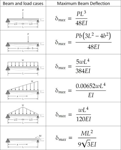
The formula for beam deflection is given by the equation: Δ = (W L^3) / (3 E I), where Δ is the deflection, W is the load, L is the length of the beam, E is the Young's modulus, and I is the moment of inertia of the beam's cross-section. This equation is used in the calculator to calculate the deflection of the beam.
Types of Beam Supports
There are several types of beam supports, including simply supported, fixed, and cantilevered. The simply supported beam is supported on both ends and is free to rotate at the supports. The fixed beam is supported on both ends and is not free to rotate at the supports. The cantilevered beam is supported on one end and is free to rotate at the support.
Importance of Beam Deflection
The beam deflection is an important parameter in the design of beams and other structural elements. Excessive deflection can lead to structural failure, reduced safety, and increased maintenance costs. Therefore, it is essential to calculate the beam deflection accurately using the beam deflection equations.
Limitations of the Calculator
The calculator has several limitations, including the assumption of a linear elastic material, a constant cross-section, and a single load at the center. The calculator also assumes that the beam is simply supported on both ends. These limitations should be considered when using the calculator to calculate the beam deflection.
| Parameter | Unit | Description |
|---|---|---|
| Load | N | The load applied to the beam |
| Length | m | The length of the beam |
| Young's Modulus | Pa | The Young's modulus of the material |
| Moment of Inertia | m^4 | The moment of inertia of the beam's cross-section |
| Deflection | m | The deflection of the beam |
What is the formula for the deflection of a beam fixed at both ends?
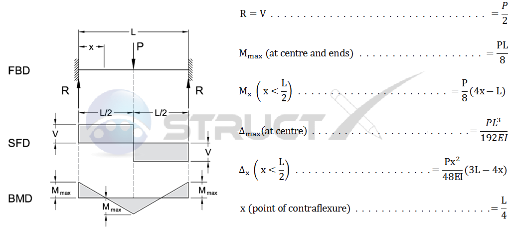
The formula for the deflection of a beam fixed at both ends is given by the equation: Δ = (W L^3) / (192 E I), where Δ is the deflection, W is the load, L is the length of the beam, E is the modulus of elasticity, and I is the moment of inertia. This formula is used to calculate the maximum deflection of a beam that is fixed at both ends and subjected to a uniform load.
Understanding the Variables
The variables in the formula are crucial in determining the deflection of the beam. The load (W) is the external force applied to the beam, the length (L) is the distance between the two fixed ends, the modulus of elasticity (E) is a measure of the beam's ability to resist deformation, and the moment of inertia (I) is a measure of the beam's resistance to bending. The formula can be broken down into the following steps:
- Calculate the load (W) applied to the beam
- Measure the length (L) of the beam
- Determine the modulus of elasticity (E) and moment of inertia (I) of the beam material
Types of Loads
The type of load applied to the beam can affect the deflection calculation. There are several types of loads, including point loads, uniformly distributed loads, and varying loads. Each type of load requires a different calculation to determine the deflection. For example:
- Point loads require a calculation of the load intensity and the distance from the load to the fixed ends
- Uniformly distributed loads require a calculation of the load intensity and the length of the beam
- Varying loads require a calculation of the load intensity and the length of the beam, as well as the load distribution
Beam Materials
The beam material can also affect the deflection calculation. Different materials have different modulus of elasticity and moment of inertia values, which must be taken into account when calculating the deflection. For example:
- Steel beams have a high modulus of elasticity and moment of inertia, resulting in low deflection
- Aluminum beams have a lower modulus of elasticity and moment of inertia, resulting in higher deflection
- Wood beams have a variable modulus of elasticity and moment of inertia, depending on the type of wood and the moisture content
Boundary Conditions
The boundary conditions of the beam can also affect the deflection calculation. The beam can be fixed at both ends, fixed at one end and free at the other, or simply supported at both ends. Each boundary condition requires a different calculation to determine the deflection. For example:
- Fixed-fixed beams have a deflection calculation that takes into account the load and the length of the beam
- Fixed-free beams have a deflection calculation that takes into account the load and the length of the beam, as well as the moment at the fixed end
- Simply supported beams have a deflection calculation that takes into account the load and the length of the beam, as well as the reaction forces at the supports
Real-World Applications
The deflection calculation is crucial in real-world applications, such as building design, bridge construction, and machine design. The calculation is used to ensure that the beam can withstand the loads and stresses applied to it, and to prevent failure or deformation. For example:
- Building design requires a calculation of the deflection of beams and columns to ensure that the structure can withstand wind loads and seismic loads
- Bridge construction requires a calculation of the deflection of beams and girders to ensure that the bridge can withstand traffic loads and environmental loads
- Machine design requires a calculation of the deflection of shafts and axles to ensure that the machine can withstand operational loads and stresses
How do you calculate the deflection of a simple supported beam?
To calculate the deflection of a simply supported beam, you need to understand the structural analysis and beam theory. The deflection of a beam is the amount of displacement or deformation that occurs when a load is applied to it. The load can be a point load, a uniformly distributed load, or a combination of both. The deflection is calculated using the beam equation, which takes into account the flexural rigidity of the beam, the length of the beam, and the load applied.
Understanding the Beam Equation
The beam equation is a fourth-order differential equation that describes the deflection of a beam under a load. To solve this equation, you need to know the boundary conditions, which are the support conditions at the ends of the beam. For a simply supported beam, the boundary conditions are that the deflection is zero at the supports and the moment is zero at the supports. The beam equation can be solved using the following steps:
- Determine the load and the length of the beam
- Calculate the flexural rigidity of the beam
- Solve the beam equation using the boundary conditions
Calculating the Flexural Rigidity
The flexural rigidity is a measure of the stiffness of the beam and is calculated using the Young's modulus and the moment of inertia of the beam cross-section. The moment of inertia is a measure of the cross-sectional area and the distance from the neutral axis to the extreme fibers. The flexural rigidity is calculated using the following formula: EI, where E is the Young's modulus and I is the moment of inertia. The flexural rigidity can be calculated using the following steps:
- Determine the cross-sectional area and the distance from the neutral axis to the extreme fibers
- Calculate the moment of inertia using the cross-sectional area and the distance
- Calculate the flexural rigidity using the Young's modulus and the moment of inertia
Applying the Boundary Conditions
The boundary conditions are used to solve the beam equation and determine the deflection of the beam. For a simply supported beam, the boundary conditions are that the deflection is zero at the supports and the moment is zero at the supports. The boundary conditions can be applied using the following steps:
- Determine the support conditions at the ends of the beam
- Apply the boundary conditions to the beam equation
- Solve the beam equation using the boundary conditions
Using the Beam Deflection Formula
The beam deflection formula is a simplified formula that can be used to calculate the deflection of a simply supported beam. The beam deflection formula takes into account the load, the length of the beam, and the flexural rigidity. The beam deflection formula can be used to calculate the deflection using the following steps:
- Determine the load and the length of the beam
- Calculate the flexural rigidity of the beam
- Apply the beam deflection formula to calculate the deflection
Accounting for Different Load Conditions
The load conditions can affect the deflection of the beam. Different load conditions, such as a point load, a uniformly distributed load, or a combination of both, can be accounted for using the beam equation and the boundary conditions. The load conditions can be accounted for using the following steps:
- Determine the load conditions and the load distribution
- Calculate the load and the moment using the load conditions
- Apply the beam equation and the boundary conditions to calculate the deflection
What is a simply supported beam at both ends?
A simply supported beam at both ends is a type of beam that is supported at its two ends by supports that allow for rotation and translation. This means that the beam is free to rotate and move up or down at its supports, but it is not free to move horizontally. The supports at the ends of the beam are typically pins or rollers, which allow for the beam to rotate and move vertically. The load on the beam can be uniformly distributed or concentrated, and it can be applied at any point along the length of the beam.
Types of Supports
The type of support used at the ends of a simply supported beam can affect its behavior. The two main types of supports are pins and rollers. Pins allow for rotation but not translation, while rollers allow for both rotation and translation. The choice of support type depends on the application and the design requirements. For example:
- The pin support is used in applications where the beam needs to be able to rotate but not move horizontally.
- The roller support is used in applications where the beam needs to be able to rotate and move horizontally.
- The combination of pin and roller supports can be used to provide additional stability and support to the beam.
Beam Reactions
The reactions at the supports of a simply supported beam can be calculated using the equilibrium equations. The reactions at the supports are forces that act on the beam and are equal in magnitude and opposite in direction to the external forces acting on the beam. The types of reactions that occur at the supports of a simply supported beam are vertical reactions and horizontal reactions. For example:
- The vertical reactions occur at the supports due to the weight of the beam and any external loads that are applied to the beam.
- The horizontal reactions occur at the supports due to the friction between the beam and the supports.
- The combination of vertical and horizontal reactions provides the necessary support to the beam to resist the external forces.
Load Application
The load on a simply supported beam can be applied in various ways, including uniformly distributed loads, concentrated loads, and moment loads. The type of load applied to the beam can affect its behavior and the reactions at the supports. For example:
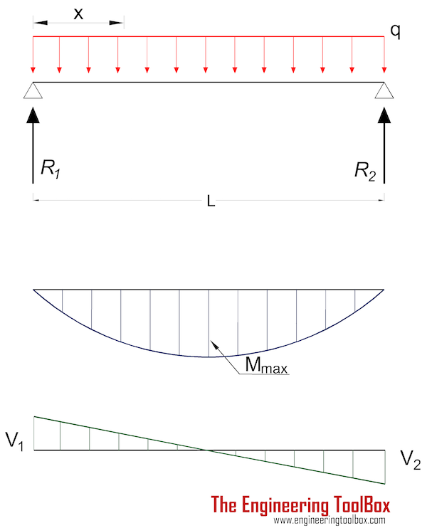
- The uniformly distributed load is a load that is distributed evenly along the length of the beam.
- The concentrated load is a load that is applied at a single point on the beam.
- The moment load is a load that causes a torque or twisting effect on the beam.
Beam Deflection
The deflection of a simply supported beam is the displacement of the beam from its original position due to the external loads. The deflection of the beam can be calculated using the beam deflection equations. The type of load applied to the beam and the properties of the beam, such as its length, width, and thickness, can affect the deflection of the beam. For example:
- The beam length affects the deflection of the beam, with longer beams experiencing greater deflection.
- The beam width and thickness affect the stiffness of the beam, with wider and thicker beams experiencing less deflection.
- The load type and magnitude also affect the deflection of the beam, with greater loads causing greater deflection.
Design Considerations
The design of a simply supported beam requires consideration of several factors, including the load on the beam, the beam properties, and the support conditions. The designer must ensure that the beam is able to resist the external forces and provide sufficient support to the load. For example:
- The designer must select a beam with sufficient strength and stiffness to resist the external loads.
- The designer must determine the support conditions and ensure that the beam is properly supported.
- The designer must check the beam deflection and ensure that it is within acceptable limits.
How do you calculate the stress of a beam?

To calculate the stress of a beam, you need to consider the forces acting on it, such as bending moments, shear forces, and torque. The stress calculation involves determining the normal stress and shear stress at different points along the beam. This requires knowledge of the beam's geometry, material properties, and the load applied to it. The calculation can be complex, but it's essential for ensuring the beam can withstand the anticipated loads without failure.
Understanding Beam Geometry
The geometry of the beam plays a crucial role in determining the stress. The beam's length, width, and thickness all impact the calculation. To calculate the stress, you need to know the beam's cross-sectional area and moment of inertia. The moment of inertia is a measure of the beam's resistance to bending and is calculated using the beam's dimensions. Here are the key factors to consider:
- The beam's length and boundary conditions affect the stress calculation.
- The cross-sectional area and moment of inertia are essential for determining the beam's resistance to bending and shear.
- The beam's material properties, such as Young's modulus and Poisson's ratio, also impact the stress calculation.
Types of Loads on Beams
Beams can be subjected to various types of loads, including point loads, uniformly distributed loads, and moments. Each type of load affects the beam's stress differently. Point loads cause concentrated stress, while uniformly distributed loads cause distributed stress. Moments cause torsional stress. To calculate the stress, you need to consider the type and magnitude of the load. Here are the key factors to consider:
- Point loads cause concentrated stress at the point of application.
- Uniformly distributed loads cause distributed stress along the length of the beam.
- Moments cause torsional stress and can lead to twisting of the beam.
Calculating Normal Stress
Normal stress occurs when a force is applied perpendicular to the beam's cross-sectional area. To calculate the normal stress, you need to divide the force by the cross-sectional area. The normal stress calculation is essential for determining the beam's resistance to tension and compression. Here are the key factors to consider:
- The force applied to the beam affects the normal stress calculation.
- The cross-sectional area of the beam is essential for determining the normal stress.
- The material properties, such as Young's modulus, impact the normal stress calculation.
Calculating Shear Stress
Shear stress occurs when a force is applied parallel to the beam's cross-sectional area. To calculate the shear stress, you need to divide the force by the cross-sectional area and consider the moment of inertia. The shear stress calculation is essential for determining the beam's resistance to shear. Here are the key factors to consider:
- The force applied to the beam affects the shear stress calculation.
- The cross-sectional area and moment of inertia are essential for determining the shear stress.
- The material properties, such as Poisson's ratio, impact the shear stress calculation.
Beam Stress Analysis Software
There are various software tools available for beam stress analysis, such as Finite Element Analysis (FEA) and beam theory software. These tools can help simplify the stress calculation process and provide accurate results. To use these tools effectively, you need to have a good understanding of the beam's geometry, material properties, and load conditions. Here are the key factors to consider:
- The software tool used for beam stress analysis affects the accuracy of the results.
- The beam's geometry and material properties must be accurately inputted into the software.
- The load conditions, including point loads and uniformly distributed loads, must be correctly applied in the software.
Frequently Asked Questions (FAQs)
What is the Beam Deflection Equations Calculator and how does it support beams with a single load at the center?
The Beam Deflection Equations Calculator is a tool designed to calculate the deflection and stress of a beam under various load conditions. In the case of a beam supported on both ends with a single load at the center, the calculator uses the equations of motion to determine the deflection and bending moment at any point along the beam. This is achieved by applying the boundary conditions of the problem, which include the support reactions at the ends of the beam and the load at the center. The calculator then uses these conditions to solve for the deflection and stress in the beam, providing the user with a clear understanding of the beam's behavior under the given load conditions.
How does the calculator account for the type of load and its position on the beam?
The Beam Deflection Equations Calculator accounts for the type of load and its position on the beam by using load functions to describe the load distribution along the beam. For a single load at the center of the beam, the calculator uses a point load function to represent the load. This function is then used in conjunction with the equations of motion to determine the deflection and bending moment at any point along the beam. The calculator also allows the user to specify the magnitude and position of the load, providing a high degree of flexibility and accuracy in the calculation. By using load functions and equations of motion, the calculator is able to provide a detailed analysis of the beam's behavior under various load conditions, including the maximum deflection and stress.
What are the limitations of the Beam Deflection Equations Calculator for beams supported on both ends with a single load at the center?
The Beam Deflection Equations Calculator has several limitations when it comes to calculating the deflection and stress of beams supported on both ends with a single load at the center. One of the main limitations is that the calculator assumes a linear elastic material behavior, which may not be accurate for all types of materials. Additionally, the calculator assumes that the beam is prismatic, meaning that it has a constant cross-sectional area along its length. The calculator also assumes that the supports are rigid, meaning that they do not deform under the load. These assumptions can limit the accuracy of the calculator for certain types of beams or load conditions. Furthermore, the calculator does not account for dynamic loads or impact loads, which can cause vibrations and stress waves in the beam.
How can the Beam Deflection Equations Calculator be used in real-world engineering applications?
The Beam Deflection Equations Calculator can be used in a variety of real-world engineering applications, including the design of buildings, bridges, and machines. By using the calculator to determine the deflection and stress of a beam under various load conditions, engineers can ensure that their designs are safe and efficient. The calculator can also be used to optimize beam designs, by minimizing the weight and cost of the beam while still meeting the required strength and stiffness requirements. Additionally, the calculator can be used to analyze existing beam structures, allowing engineers to predict their behavior under different load conditions and identify potential failure modes. By using the Beam Deflection Equations Calculator in conjunction with other engineering tools and techniques, engineers can create reliable and efficient beam designs that meet the needs of a wide range of applications.
Deja una respuesta
Entradas Relacionadas