
Positional Tolerance Hole Pattern Calculator and Graph

The Positional Tolerance Hole Pattern Calculator and Graph is a tool designed to simplify the process of calculating and visualizing hole patterns with positional tolerances. This calculator takes into account the complexities of geometric dimensioning and tolerancing, providing accurate results and a graphical representation of the hole pattern. By using this calculator, engineers and designers can ensure that their designs meet the required tolerances and specifications, reducing errors and improving overall product quality. The calculator's user-friendly interface makes it accessible to users of all skill levels. It is a valuable resource for industries such as manufacturing and engineering.
- Understanding the Positional Tolerance Hole Pattern Calculator and Graph
- How do you calculate hole position tolerance?
- What is the formula for the calculation of hole tolerance?
- How to check position tolerance in GD&T?
-
Frequently Asked Questions (FAQs)
- What is the purpose of the Positional Tolerance Hole Pattern Calculator and Graph?
- How does the Positional Tolerance Hole Pattern Calculator and Graph work?
- What are the benefits of using the Positional Tolerance Hole Pattern Calculator and Graph?
- Can the Positional Tolerance Hole Pattern Calculator and Graph be used for complex hole patterns?
Understanding the Positional Tolerance Hole Pattern Calculator and Graph
The Positional Tolerance Hole Pattern Calculator and Graph is a tool used in the field of engineering and manufacturing to calculate and visualize the positional tolerance of hole patterns in mechanical parts. Positional tolerance refers to the amount of variation allowed in the location of a feature, such as a hole, from its nominal position. This calculator and graph are essential in ensuring that the parts manufactured meet the required specifications and standards.
Introduction to Positional Tolerance
Positional tolerance is a critical aspect of geometric dimensioning and tolerancing (GD&T). It defines the permissible variation in the location of a feature from its nominal position. The tolerance zone is the area within which the feature must lie to be considered acceptable. The Positional Tolerance Hole Pattern Calculator and Graph helps engineers and manufacturers to determine the optimal tolerance for a given hole pattern, taking into account factors such as the hole diameter, pitch, and orientation.
How to Use the Calculator and Graph
To use the Positional Tolerance Hole Pattern Calculator and Graph, users need to input the nominal dimensions of the hole pattern, including the hole diameter, pitch, and number of holes. The calculator then generates a graph showing the tolerance zone for each hole, taking into account the specified tolerance. The graph provides a visual representation of the allowable variation in the location of each hole, making it easier to identify potential issues and optimize the design.
Benefits of Using the Calculator and Graph
The Positional Tolerance Hole Pattern Calculator and Graph offers several benefits, including:
| Benefit | Description |
|---|---|
| Improved Accuracy | Ensures that the parts manufactured meet the required specifications and standards |
| Reduced Errors | Minimizes the risk of errors in the manufacturing process |
| Increased Efficiency | Streamlines the design and manufacturing process |
| Cost Savings | Reduces waste and minimizes the need for rework |
| Enhanced Collaboration | Facilitates communication and collaboration between designers, engineers, and manufacturers |
Common Applications of the Calculator and Graph
The Positional Tolerance Hole Pattern Calculator and Graph is commonly used in various industries, including aerospace, automotive, medical devices, and consumer products. It is particularly useful in applications where precision and accuracy are critical, such as in the manufacture of engine components, gearboxes, and bearing assemblies.
Future Developments and Advancements
The Positional Tolerance Hole Pattern Calculator and Graph is a continuously evolving tool, with ongoing research and development aimed at improving its accuracy and efficiency. Future developments are likely to include the integration of artificial intelligence and machine learning algorithms to enhance the calculator's predictive capabilities and optimization of hole patterns. Additionally, the graph is expected to become more interactive and intuitive, allowing users to easily visualize and analyze the results.
How do you calculate hole position tolerance?
To calculate hole position tolerance, you need to consider the geometric dimensioning and tolerancing (GD&T) principles. The position tolerance of a hole is the amount of variation allowed in the location of the hole from its nominal position. This tolerance is critical in ensuring that the hole is properly aligned with other features, such as shafts or pins, to ensure proper assembly and functionality. The calculation involves determining the datum features, which are the reference points for the hole's position, and then applying the tolerance values to these datums.
Understanding Datum Features
The calculation of hole position tolerance starts with identifying the datum features, which are the reference points for the hole's position. These features are typically planned and constructed to provide a stable reference frame for the hole. The datum features can be points, lines, or surfaces, and they are used to establish the nominal position of the hole. To calculate the hole position tolerance, you need to consider the following:
- Identify the primary datum feature, which is the main reference point for the hole's position.
- secondary datum features, which provide additional reference points for the hole's position.
- Establish the tolerance values for the datum features, which define the allowed variation in the hole's position.
Applying Geometric Dimensioning and Tolerancing (GD&T) Principles
The GD&T principles provide a standardized method for specifying tolerances and geometric requirements for features like holes. To calculate the hole position tolerance, you need to apply these principles to the datum features. This involves specifying the tolerance values for the position of the hole, which defines the allowed variation in the hole's location. The GD&T principles also provide a framework for analyzing the tolerance values and determining the worst-case scenario for the hole's position. To apply the GD&T principles, you need to consider the following:
- Specify the position tolerance value, which defines the allowed variation in the hole's location.
- Determine the orientation tolerance value, which defines the allowed variation in the hole's orientation.
- Establish the form tolerance value, which defines the allowed variation in the hole's shape.
Tolerance Values and Calculations
The tolerance values for the hole position are typically specified as a range of values, which defines the allowed variation in the hole's location. These values can be calculated using various formulas and techniques, such as the Root Sum Square (RSS) method or the worst-case analysis method. To calculate the hole position tolerance, you need to consider the following:
- Determine the nominal position of the hole, which is the ideal location of the hole.
- Calculate the tolerance values for the datum features, which define the allowed variation in the hole's position.
- Apply the GD&T principles to determine the worst-case scenario for the hole's position.
Datum Feature Construction and Verification
The datum features are critical in defining the hole position tolerance, and their construction and verification are essential to ensure that the hole is properly aligned. The datum features can be constructed using various methods, such as coordinate measuring machines (CMMs) or laser scanners. To verify the datum features, you need to consider the following:
- Verify the accuracy of the datum features using measurement techniques.
- Check the repeatability of the datum features to ensure that they are stable and consistent.
- Validate the datum features against the design specifications to ensure that they meet the required tolerances.
Implications of Hole Position Tolerance on Assembly and Functionality
The hole position tolerance has significant implications for the assembly and functionality of the product. A tight tolerance can ensure that the hole is properly aligned with other features, such as shafts or pins, but it can also increase the manufacturing cost and complexity. A loose tolerance can reduce the manufacturing cost and complexity, but it can also compromise the functionality and performance of the product. To determine the optimal hole position tolerance, you need to consider the following:
- Balance the manufacturing cost and complexity against the required functionality and performance.
- Specify the tolerance values based on the design requirements and manufacturing capabilities.
- Verify the assembly and functionality of the product to ensure that the hole position tolerance meets the required standards.
What is the formula for the calculation of hole tolerance?

The formula for calculating hole tolerance is based on the International Organization for Standardization (ISO) system, which defines the limits of size for a hole. The formula is: iTunes = (IT + 0.001 D), where iTunes is the tolerance of the hole, IT is the International Tolerance grade, and D is the diameter of the hole.
Understanding Hole Tolerance Calculation
To calculate the hole tolerance, it is essential to understand the fundamentals of the ISO system. The ISO system provides a set of rules for calculating the limits of size for a hole. The calculation involves determining the maximum and minimum limits of size for the hole, based on the nominal diameter and the tolerance grade. The formula for calculating the hole tolerance is as follows:
- Determine the nominal diameter of the hole
- Select the tolerance grade based on the required precision
- Calculate the maximum and minimum limits of size using the ISO formula
Factors Affecting Hole Tolerance Calculation
Several factors can affect the calculation of hole tolerance, including the material of the part, the manufacturing process, and the required precision. The material of the part can affect the tolerance due to variations in density and elasticity. The manufacturing process can also impact the tolerance, as different processes can produce variations in size and shape. The required precision is also a critical factor, as it determines the tolerance grade and the limits of size for the hole.
- Material properties can affect the tolerance of the hole
- Manufacturing processes can impact the tolerance of the hole
- Required precision determines the tolerance grade and limits of size
Hole Tolerance Calculation Methods
There are several methods for calculating hole tolerance, including the ISO system, the ANSI system, and the JIS system. Each system has its own set of rules and formulas for calculating the limits of size for a hole. The ISO system is the most widely used system, and it provides a set of standards for calculating the tolerance of a hole. The ANSI system is used in the United States, and it provides a set of standards for calculating the tolerance of a hole.
- ISO system is the most widely used system for calculating hole tolerance
- ANSI system is used in the United States for calculating hole tolerance
- JIS system is used in Japan for calculating hole tolerance
Applications of Hole Tolerance Calculation
The calculation of hole tolerance has several applications in engineering and manufacturing. It is used to determine the limits of size for a hole, which is critical in the design and manufacture of parts and assemblies. The calculation of hole tolerance is also used to inspect and test parts and assemblies, to ensure that they meet the required specifications.
- Design and manufacture of parts and assemblies require hole tolerance calculation
- Inspection and testing of parts and assemblies require hole tolerance calculation
- Quality control requires hole tolerance calculation to ensure product quality
Importance of Accurate Hole Tolerance Calculation
The accurate calculation of hole tolerance is critical in engineering and manufacturing, as it ensures that parts and assemblies are interchangeable and function as intended. Inaccurate calculation of hole tolerance can result in parts and assemblies that do not fit or function properly, leading to rework, scrap, and waste. The accurate calculation of hole tolerance requires a thorough understanding of the ISO system and the factors that affect the tolerance of a hole.
- Accurate calculation of hole tolerance ensures interchangeability of parts and assemblies
- Inaccurate calculation of hole tolerance can result in rework, scrap, and waste
- Thorough understanding of the ISO system is required for accurate calculation of hole tolerance
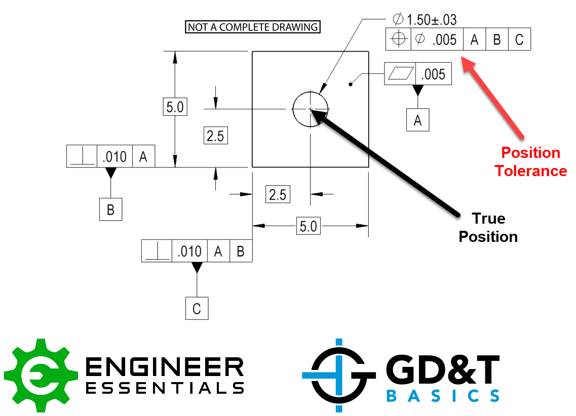
How to check position tolerance in GD&T?
To check position tolerance in GD&T (Geometric Dimensioning and Tolerancing), it's essential to understand the concept of position tolerance and how it applies to the datum features of a part. Position tolerance is a GD&T concept that defines the allowable variation in the location of a feature or a group of features from their true position. This tolerance is specified using a tolerance zone, which is the area within which the feature or features must lie.
Understanding Position Tolerance
To check position tolerance, one must first identify the datum features and the tolerance zone specified in the GD&T drawing or specification. The datum features are the reference points, lines, or planes from which the position of other features is measured. The tolerance zone is the area within which the feature or features must lie, and it is defined by the position tolerance value.
- The position tolerance value is specified in the GD&T drawing or specification.
- The datum features are identified as the reference points, lines, or planes.
- The tolerance zone is calculated based on the position tolerance value and the datum features.
Calculating Position Tolerance
Calculating position tolerance involves determining the true position of the feature or features and comparing it to the tolerance zone. The true position is the theoretical location of the feature or features, and it is calculated using the datum features and the GD&T drawing or specification. The position tolerance is then calculated as the difference between the true position and the actual position of the feature or features.
- The true position is calculated using the datum features and the GD&T drawing or specification.
- The actual position is measured using coordinate measuring machines (CMMs) or other measurement tools.
- The position tolerance is calculated as the difference between the true position and the actual position.
Using Datum Features
Datum features are reference points, lines, or planes that are used to locate and orient the part or assembly. They provide a common reference for measurement and inspection, and they are essential for checking position tolerance. The datum features are identified in the GD&T drawing or specification, and they are used to calculate the true position of the feature or features.
- The datum features are identified in the GD&T drawing or specification.
- The datum features are used to calculate the true position of the feature or features.
- The datum features provide a common reference for measurement and inspection.
Inspecting Position Tolerance
Inspecting position tolerance involves measuring the actual position of the feature or features and comparing it to the tolerance zone. This is typically done using coordinate measuring machines (CMMs) or other measurement tools. The inspection process involves aligning the part or assembly with the datum features, measuring the actual position of the feature or features, and comparing it to the tolerance zone.
- The part or assembly is aligned with the datum features.
- The actual position of the feature or features is measured using CMMs or other measurement tools.
- The actual position is compared to the tolerance zone to determine if it is within the allowed tolerance.
Common Issues with Position Tolerance
Common issues with position tolerance include datum feature errors, measurement errors, and tolerance stack-up. Datum feature errors occur when the datum features are not accurately defined or measured. Measurement errors occur when the actual position of the feature or features is not accurately measured. Tolerance stack-up occurs when the tolerances of multiple features add up to exceed the allowed tolerance.
- Datum feature errors can occur due to inaccurate definition or measurement.
- Measurement errors can occur due to inaccurate measurement tools or techniques.
- Tolerance stack-up can occur when the tolerances of multiple features add up to exceed the allowed tolerance.
Frequently Asked Questions (FAQs)
What is the purpose of the Positional Tolerance Hole Pattern Calculator and Graph?
The Positional Tolerance Hole Pattern Calculator and Graph is a tool designed to help engineers and designers calculate and visualize the positional tolerance of hole patterns in mechanical parts. Positional tolerance refers to the allowed variation in the location of a feature, such as a hole, within a specified datum or reference point. The calculator and graph provide a quick and easy way to determine the maximum material condition (MMC) and least material condition (LMC) of a hole pattern, as well as the positional tolerance zone. This information is crucial in ensuring that parts fit together properly and function as intended. By using the Positional Tolerance Hole Pattern Calculator and Graph, users can optimize their designs and reduce the risk of manufacturing errors.
How does the Positional Tolerance Hole Pattern Calculator and Graph work?
The Positional Tolerance Hole Pattern Calculator and Graph works by inputting the nominal dimensions of the hole pattern, including the diameter and spacing of the holes, as well as the positional tolerance specifications. The calculator then uses geometric calculations to determine the positional tolerance zone and calculates the MMC and LMC of the hole pattern. The results are then graphically represented on a coordinate system, allowing users to visualize the positional tolerance zone and understand how the tolerances affect the fit and function of the parts. The calculator also takes into account other factors, such as the material properties and manufacturing processes, to provide a comprehensive analysis of the hole pattern. By using the Positional Tolerance Hole Pattern Calculator and Graph, users can streamline their design process and improve the accuracy of their designs.
What are the benefits of using the Positional Tolerance Hole Pattern Calculator and Graph?
The Positional Tolerance Hole Pattern Calculator and Graph offers several benefits to users, including improved accuracy and reduced errors in design and manufacturing. By calculating and visualizing the positional tolerance zone, users can ensure that their parts fit together properly and function as intended, reducing the risk of rework and scrap. The calculator and graph also save time and reduce costs by streamlining the design process and minimizing the need for physical prototypes. Additionally, the Positional Tolerance Hole Pattern Calculator and Graph can be used to communicate design intent and tolerance requirements to manufacturing teams and suppliers, ensuring that everyone involved in the production process is on the same page. By using the Positional Tolerance Hole Pattern Calculator and Graph, users can optimize their designs, improve their manufacturing processes, and increase their competitive edge.
Can the Positional Tolerance Hole Pattern Calculator and Graph be used for complex hole patterns?
Yes, the Positional Tolerance Hole Pattern Calculator and Graph can be used for complex hole patterns, including irregular shapes and non-uniform spacing. The calculator is designed to handle a wide range of input parameters, including multiple datums and nested tolerances. The graphical representation of the positional tolerance zone can also be used to visualize and analyze complex hole patterns, making it easier to understand and communicate the design intent and tolerance requirements. Additionally, the Positional Tolerance Hole Pattern Calculator and Graph can be used in conjunction with other tools, such as computer-aided design (CAD) software, to create and analyze complex hole patterns. By using the Positional Tolerance Hole Pattern Calculator and Graph, users can tackle even the most challenging hole pattern designs with confidence and accuracy, and ensure that their parts meet the required specifications and functional requirements.
Deja una respuesta
Entradas Relacionadas