
Diameter Change Press and Shrink Fit Formulae and Calculator

The Diameter Change Press and Shrink Fit is a process used to join two parts together by heating or cooling one of them to create a temporary size change, allowing for a precise fit. This method is crucial in various engineering applications, including manufacturing and assembly. The formulae and calculator for Diameter Change Press and Shrink Fit enable engineers to accurately calculate the required size changes and predict the resulting fit. Understanding these formulae is essential for achieving a secure and precise connection between components. Accurate calculations ensure reliability and efficiency in the assembly process.
- Diameter Change Press and Shrink Fit Formulae and Calculator
- How to calculate press fit load?
- How much interference for shrink fit?
- How do you calculate fit pressure?
-
Frequently Asked Questions (FAQs)
- What is the purpose of using Diameter Change Press and Shrink Fit Formulae and Calculator in engineering applications?
- How does the Diameter Change Press and Shrink Fit Formulae and Calculator work, and what are the key input parameters?
- What are the benefits of using the Diameter Change Press and Shrink Fit Formulae and Calculator in engineering design and manufacture?
- What are some common applications of the Diameter Change Press and Shrink Fit Formulae and Calculator in various industries?
Diameter Change Press and Shrink Fit Formulae and Calculator
The Diameter Change Press and Shrink Fit Formulae and Calculator are essential tools in engineering and manufacturing, particularly in the design and assembly of mechanical components. These tools enable engineers to calculate the required diameter change for a press fit or shrink fit, ensuring a secure and precise connection between parts. The calculator takes into account various factors, including the material properties, temperature, and interference fit, to provide accurate results.
Introduction to Press Fit and Shrink Fit
Press fit and shrink fit are two common methods used to assemble mechanical components. Press fit involves forcibly inserting a part into a mating component, creating a tight interference fit. Shrink fit, on the other hand, involves heating or cooling a part to create a temporary clearance, allowing it to be assembled, and then returning it to its original size to create a secure fit. Both methods require precise calculations to ensure a successful assembly.
Key Factors Affecting Diameter Change
Several factors affect the required diameter change for a press fit or shrink fit, including:
- Material properties: The coefficient of thermal expansion, Young's modulus, and Poisson's ratio of the materials involved.
- Temperature: The temperature difference between the parts and the surrounding environment.
- Interference fit: The desired clearance or interference between the parts.
- Assembly method: The method used to assemble the parts, such as press fitting or shrink fitting.
Formulae for Diameter Change Calculation
The formulae for calculating the required diameter change for a press fit or shrink fit are based on the material properties and assembly conditions. The diameter change formula for a press fit is given by:
Δd = (d2 - d1) / (1 + (E1 / E2) (d2 / d1))
where Δd is the diameter change, d1 and d2 are the diameters of the parts, and E1 and E2 are the Young's moduli of the materials.
Calculator Inputs and Outputs
The Diameter Change Press and Shrink Fit Calculator requires the following inputs:
- Part diameters: The diameters of the parts to be assembled.
- Material properties: The coefficient of thermal expansion, Young's modulus, and Poisson's ratio of the materials involved.
- Temperature: The temperature difference between the parts and the surrounding environment.
- Interference fit: The desired clearance or interference between the parts.
The calculator outputs the required diameter change and the resulting interference fit.
Applications and Limitations
The Diameter Change Press and Shrink Fit Formulae and Calculator have numerous applications in engineering and manufacturing, including:
- Mechanical component design: Ensuring precise and secure connections between parts.
- Assembly process optimization: Minimizing assembly time and reducing the risk of component damage.
- Quality control: Verifying the accuracy of assembled components.
However, the calculator has limitations, such as:
- Assuming ideal material behavior: Ignoring material defects, anisotropy, and non-linear behavior.
- Neglecting external factors: Ignoring factors like vibrations, corrosion, and wear.
The following table summarizes the key factors and formulae:
| Factor | Formula | Unit |
|---|---|---|
| Diameter change | Δd = (d2 - d1) / (1 + (E1 / E2) (d2 / d1)) | mm |
| Interference fit | IF = (d2 - d1) - Δd | μm |
| Young's modulus | E = stress / strain | MPa |
| Coefficient of thermal expansion | α = change in length / (L ΔT) | 1/°C |
| Poisson's ratio | ν = - (transverse strain / axial strain) | - |
How to calculate press fit load?

To calculate press fit load, you need to consider several factors, including the interference fit, friction coefficient, and material properties. The press fit load is the force required to assemble or disassemble two parts that are designed to fit together with a certain amount of interference. This type of fit is commonly used in mechanical engineering to ensure a secure and precise connection between components.
Understanding Press Fit Terminology
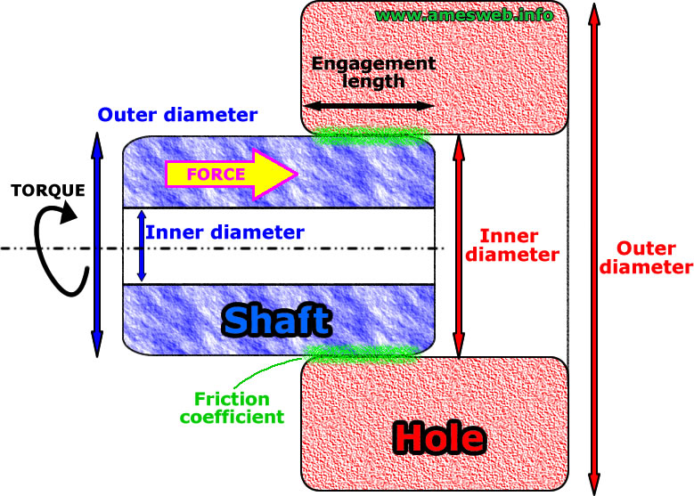
The calculation of press fit load involves understanding key terms such as interference, clearance, and transition fit. Interference refers to the difference between the outer diameter of the shaft and the inner diameter of the hole, which creates a frictional force that holds the parts together. The friction coefficient is a measure of the resistance to sliding between the two surfaces. To calculate press fit load, you need to know the following:
- The interference fit value, which is typically specified in the design requirements.
- The friction coefficient, which depends on the surface roughness and material properties of the parts.
- The diameter of the shaft and the hole, as well as the length of the parts.
Calculating Press Fit Load using Formulas
The press fit load can be calculated using formulas that take into account the geometric parameters and material properties of the parts. One common formula is the Lame equation, which relates the interference fit to the contact pressure and friction coefficient. To apply this formula, you need to know the following:
- The Lame constant, which depends on the material properties and geometric parameters of the parts.
- The interference fit value, which is typically specified in the design requirements.
- The friction coefficient, which depends on the surface roughness and material properties of the parts.
Factors Affecting Press Fit Load
Several factors can affect the press fit load, including surface roughness, material properties, and geometric parameters. The surface roughness can affect the friction coefficient, which in turn affects the press fit load. The material properties, such as yield strength and elastic modulus, can also impact the press fit load. To account for these factors, you need to consider the following:
- The surface roughness of the parts, which can be measured using profilometry or other techniques.
- The material properties, which can be found in material databases or suppliers' catalogs.
- The geometric parameters, such as diameter and length, which are typically specified in the design requirements.
Press Fit Load Calculation Tools and Software
Several tools and software are available to help calculate press fit load, including spreadsheet programs and computer-aided design (CAD) software. These tools can simplify the calculation process and reduce the risk of errors. To use these tools effectively, you need to know the following:
- The input parameters, such as interference fit, friction coefficient, and geometric parameters.
- The output values, such as press fit load and contact pressure.
- The limitations and assumptions of the tool or software, which can affect the accuracy of the results.
Applications and Examples of Press Fit Load Calculation
The calculation of press fit load has numerous applications in mechanical engineering, including shaft-hub connections, gearboxes, and bearings. For example, in aerospace engineering, press fit loads are critical in ensuring the structural integrity of aircraft components. To apply press fit load calculation in practice, you need to consider the following:
- The design requirements, which specify the interference fit and friction coefficient values.
- The material properties, which affect the strength and stiffness of the parts.
- The operating conditions, such as temperature and vibration, which can impact the press fit load.
How much interference for shrink fit?
The amount of interference for a shrink fit can vary depending on the specific application and the materials involved. Generally, the interference is calculated based on the diameter of the shaft and the hole, as well as the material properties of the components. A typical range for interference in a shrink fit is between 0.001 and 0.01 inches (0.025 to 0.254 millimeters) per inch (25.4 millimeters) of diameter.
Calculating Interference for Shrink Fit
Calculating the interference for a shrink fit involves determining the diameter of the shaft and the hole, as well as the material properties of the components. The interference can be calculated using the following formula: interference = (outer diameter - inner diameter) / 2. Some key factors to consider when calculating interference include:
- Diameter of the shaft and hole: The diameter of the shaft and hole will affect the amount of interference required for a secure fit.
- Material properties: The material properties of the components, such as thermal expansion and elasticity, will affect the amount of interference required.
- Temperature: The temperature at which the shrink fit will be used will affect the amount of interference required, as temperature can affect the material properties of the components.
Factors Affecting Interference in Shrink Fit
Several factors can affect the interference in a shrink fit, including temperature, material properties, and surface finish. The interference can be affected by the thermal expansion of the materials, which can cause the components to expand or contract. Some key factors to consider include:
- Thermal expansion: The thermal expansion of the materials can cause the components to expand or contract, affecting the interference.
- Material properties: The material properties of the components, such as elasticity and plasticity, will affect the amount of interference required.
- Surface finish: The surface finish of the components can affect the interference, as a rough surface can increase the friction between the components.
Types of Interference in Shrink Fit
There are several types of interference that can occur in a shrink fit, including press fit, shrink fit, and expansion fit. The type of interference will depend on the specific application and the material properties of the components. Some key types of interference include:
- Press fit: A press fit is a type of interference where the components are pressed together using a press or other tool.
- Shrink fit: A shrink fit is a type of interference where the components are heated or cooled to create a tight fit.
- Expansion fit: An expansion fit is a type of interference where the components are expanded or contracted to create a tight fit.
Advantages of Interference in Shrink Fit
The use of interference in a shrink fit can provide several advantages, including increased security and reduced vibration. The interference can help to secure the components together, reducing the risk of loosening or failure. Some key advantages of interference in a shrink fit include:
- Increased security: The interference can help to secure the components together, reducing the risk of loosening or failure.
- Reduced vibration: The interference can help to reduce vibration between the components, improving the overall performance of the system.
- Improved durability: The interference can help to improve the durability of the components, reducing the risk of wear and tear.
The use of interference in a shrink fit can be applied to a wide range of applications, including mechanical engineering, aerospace engineering, and automotive engineering. The interference can be used to secure components together, reducing the risk of loosening or failure. Some key applications of interference in a shrink fit include:
- Mechanical engineering: The use of interference in a shrink fit can be applied to mechanical engineering applications, such as gearboxes and bearings.
- Aerospace engineering: The use of interference in a shrink fit can be applied to aerospace engineering applications, such as aircraft engines and rocket propulsion systems.
- Automotive engineering: The use of interference in a shrink fit can be applied to automotive engineering applications, such as engine components and transmissions.
How do you calculate fit pressure?

To calculate fit pressure, you need to understand the concept of pressure and how it relates to the fit of a garment or a product. Fit pressure refers to the pressure exerted by a garment or a product on the body, and it is an important factor in determining the comfort and usability of the product. The calculation of fit pressure involves measuring the force exerted by the garment or product on the body and the area over which this force is applied.
Understanding Fit Pressure
The calculation of fit pressure requires an understanding of the physical properties of the garment or product, such as its material, thickness, and density. The fit pressure is calculated by dividing the force exerted by the garment or product by the area over which this force is applied. This can be expressed as: fit pressure = force / area. The following are the key factors to consider when calculating fit pressure:
- The force exerted by the garment or product, which can be measured using a force sensor or a load cell.
- The area over which the force is applied, which can be measured using a caliper or a ruler.
- The material properties of the garment or product, such as its elasticity and viscosity, which can affect the fit pressure.
Measuring Fit Pressure
Measuring fit pressure requires specialized equipment, such as a pressure sensor or a force sensor. These sensors can be placed on the body or on the garment or product to measure the force exerted and the area over which this force is applied. The data from these sensors can then be used to calculate the fit pressure. The following are the steps involved in measuring fit pressure:
- Place the pressure sensor or force sensor on the body or on the garment or product.
- Measure the force exerted by the garment or product using the sensor.
- Measure the area over which the force is applied using a caliper or a ruler.
Calculating Fit Pressure
The calculation of fit pressure involves dividing the force exerted by the garment or product by the area over which this force is applied. This can be expressed as: fit pressure = force / area. The following are the key factors to consider when calculating fit pressure:
- The unit of measurement for the force and area, which can be Newtons and square meters, respectively.
- The material properties of the garment or product, such as its elasticity and viscosity, which can affect the fit pressure.
- The body shape and size, which can affect the fit pressure.
Factors Affecting Fit Pressure
There are several factors that can affect the fit pressure, including the material properties of the garment or product, the body shape and size, and the activity level. The following are the key factors to consider:
- The material properties, such as elasticity and viscosity, which can affect the fit pressure.
- The body shape and size, which can affect the fit pressure.
- The activity level, which can affect the fit pressure.
Applications of Fit Pressure
The calculation of fit pressure has several applications, including the design of clothing, footwear, and medical devices. The following are the key applications:
- The design of clothing and footwear, where fit pressure is important for comfort and usability.
- The design of medical devices, such as prosthetics and orthotics, where fit pressure is important for comfort and functionality.
- The design of sports equipment, such as helmets and pads, where fit pressure is important for safety and performance.
Frequently Asked Questions (FAQs)
What is the purpose of using Diameter Change Press and Shrink Fit Formulae and Calculator in engineering applications?
The Diameter Change Press and Shrink Fit Formulae and Calculator is a crucial tool in engineering applications, particularly in the design and manufacture of mechanical components. Its primary purpose is to calculate the diameter change that occurs when a shrink fit is applied to a component, such as a shaft or a bearing. This calculation is essential to ensure that the interference fit between the components is accurate, which is critical for the proper functioning and longevity of the assembly. By using the formulae and calculator, engineers can determine the required diameter change and the resulting stress on the components, allowing them to optimize their design and minimize the risk of failure. The calculator also enables engineers to validate their designs and ensure that they meet the required specifications.
How does the Diameter Change Press and Shrink Fit Formulae and Calculator work, and what are the key input parameters?
The Diameter Change Press and Shrink Fit Formulae and Calculator works by using a set of mathematical formulae to calculate the diameter change and resulting stress on the components. The key input parameters required to use the calculator include the initial diameter of the component, the coefficient of thermal expansion, the temperature change, and the modulus of elasticity of the material. Additionally, the calculator requires information about the shrink fit itself, such as the interference fit and the clearance between the components. By entering these input parameters into the calculator, engineers can obtain the required diameter change and resulting stress on the components, which can then be used to optimize their design. The calculator also provides graphs and charts to help engineers visualize the results and understand the relationships between the different variables.
What are the benefits of using the Diameter Change Press and Shrink Fit Formulae and Calculator in engineering design and manufacture?
The Diameter Change Press and Shrink Fit Formulae and Calculator offers several benefits to engineers and manufacturers. One of the primary benefits is the ability to optimize designs and minimize the risk of failure. By using the calculator to determine the required diameter change and resulting stress on the components, engineers can ensure that their designs meet the required specifications and are safe and reliable. Another benefit is the ability to reduce production costs by minimizing the number of iterations required to achieve the desired interference fit. The calculator also enables engineers to validate their designs and verify that they meet the required specifications, which can help to reduce the time and cost associated with prototype testing and redesign. Additionally, the calculator can be used to investigate the effects of different materials and design parameters on the shrink fit, allowing engineers to optimize their designs and improve the performance of their components.
What are some common applications of the Diameter Change Press and Shrink Fit Formulae and Calculator in various industries?
The Diameter Change Press and Shrink Fit Formulae and Calculator has a wide range of applications in various industries, including aerospace, automotive, industrial machinery, and medical devices. In the aerospace industry, the calculator is used to design and manufacture critical components such as engine shafts and gearboxes. In the automotive industry, the calculator is used to design and manufacture transmission components and engine blocks. In the industrial machinery industry, the calculator is used to design and manufacture gearboxes, pumps, and motors. In the medical device industry, the calculator is used to design and manufacture implantable devices such as hip replacement and knee replacement components. The calculator is also used in research and development to investigate the effects of different materials and design parameters on the shrink fit, allowing engineers to optimize their designs and improve the performance of their components.
Deja una respuesta
Entradas Relacionadas