
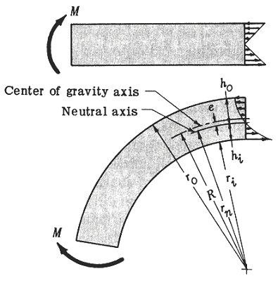
Curved T-Section Stress Formulas and Calculator
The curved T-section is a complex structural element that requires precise calculations to determine its stress and load-carrying capacity. To simplify this process, engineers and designers use curved T-section stress formulas, which take into account the section's unique geometry and loading conditions. This article provides an overview of these formulas and introduces a calculator tool that enables quick and accurate calculations of stress and moment capacity for curved T-sections, helping to ensure the safety and reliability of structures that incorporate these elements. The calculator is based on established engineering principles and formulas.
- Understanding Curved T-Section Stress Formulas and Calculator
- What is the name formula for stresses in a curved beam?
- How do you calculate the stress of a beam?
- What is m in the stress equation?
- What is the bending stress of steel?
-
Frequently Asked Questions (FAQs)
- What are the Curved T-Section Stress Formulas and how are they used in engineering applications?
- How do the Curved T-Section Stress Formulas account for the effects of curvature on stress distribution?
- What are some of the key assumptions and limitations of the Curved T-Section Stress Formulas?
- How can the Curved T-Section Stress Formulas be used in conjunction with other analysis tools and techniques to optimize the design of curved structures?
Understanding Curved T-Section Stress Formulas and Calculator
The Curved T-Section Stress Formulas and Calculator are essential tools for engineers and designers to calculate the stress and strain on curved T-sections, which are commonly used in various structural and mechanical applications. The curved T-section is a type of beam that has a curved shape, and its unique geometry requires special consideration when calculating stress and strain.
Introduction to Curved T-Section Stress Formulas
The Curved T-Section Stress Formulas are based on the theory of elasticity and the principles of mechanics of materials. These formulas take into account the curvature of the T-section, as well as the loading conditions, to calculate the stress and strain at different points on the section. The formulas are typically derived using the Euler-Bernoulli beam theory, which assumes that the beam is slender and that the cross-sectional area is constant.
Key Parameters in Curved T-Section Stress Formulas
The Curved T-Section Stress Formulas require several key parameters to calculate the stress and strain, including:
| Parameter | Description |
|---|---|
| Radius of curvature | The radius of the curved T-section |
| Thickness | The thickness of the T-section |
| Width | The width of the T-section |
| Load | The applied load on the T-section |
| Material properties | The elastic modulus and Poisson's ratio of the material |
Calculating Stress and Strain using Curved T-Section Stress Formulas
To calculate the stress and strain on a curved T-section, engineers can use the Curved T-Section Stress Formulas to determine the bending stress, tensile stress, and compressive stress at different points on the section. The formulas typically involve integrating the stress equations over the curved surface of the T-section, taking into account the boundary conditions and loading conditions.
Curved T-Section Stress Calculator
A Curved T-Section Stress Calculator is a software tool that can be used to calculate the stress and strain on curved T-sections quickly and accurately. The calculator typically requires input of the key parameters, such as the radius of curvature, thickness, width, load, and material properties. The calculator then uses the Curved T-Section Stress Formulas to calculate the stress and strain at different points on the section, providing a detailed analysis of the structural behavior of the curved T-section.
Applications of Curved T-Section Stress Formulas and Calculator
The Curved T-Section Stress Formulas and Calculator have a wide range of applications in various fields, including:
| Application | Description |
|---|---|
| Aerospace engineering | Design of aircraft and spacecraft structures |
| Automotive engineering | Design of vehicle chassis and suspension systems |
| Civil engineering | Design of bridges and buildings |
| Marine engineering | Design of ship hulls and offshore structures |
| Mechanical engineering | Design of mechanical components and systems |
What is the name formula for stresses in a curved beam?
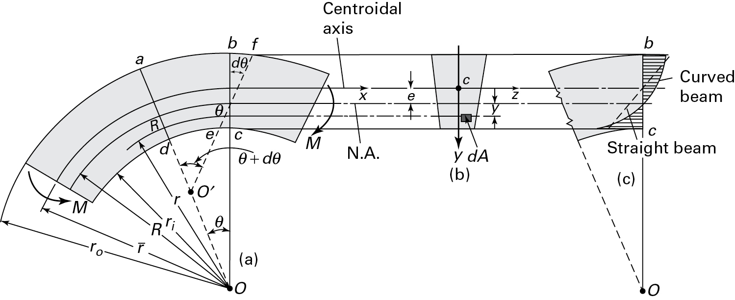
The Winkler-Bach formula is a mathematical equation used to calculate the stresses in a curved beam. This formula takes into account the curvature of the beam and the load applied to it, providing a more accurate calculation of the stresses and strains that occur in the beam.
Understanding the Winkler-Bach Formula
The Winkler-Bach formula is a complex equation that requires a thorough understanding of the beam's geometry and the load applied to it. The formula is based on the principle of superposition, which states that the stresses and strains caused by multiple loads can be calculated by adding the stresses and strains caused by each individual load. Some key factors to consider when using the Winkler-Bach formula include:
- The radius of curvature of the beam, which affects the stresses and strains that occur in the beam
- The magnitude and direction of the load applied to the beam, which determines the stresses and strains that occur in the beam
- The material properties of the beam, such as its elastic modulus and Poisson's ratio, which affect the stresses and strains that occur in the beam
Applications of the Winkler-Bach Formula
The Winkler-Bach formula has a wide range of applications in engineering, including the design of curved beams and arches. The formula is particularly useful for calculating the stresses and strains that occur in curved beams subjected to complex loads, such as bending and torsion. Some examples of applications of the Winkler-Bach formula include:
- Bridge design, where the formula is used to calculate the stresses and strains in curved beams and arches
- Building design, where the formula is used to calculate the stresses and strains in curved beams and columns
- Machine design, where the formula is used to calculate the stresses and strains in curved beams and shafts
Limitations of the Winkler-Bach Formula
While the Winkler-Bach formula is a powerful tool for calculating the stresses and strains in curved beams, it has some limitations. The formula assumes that the beam is homogeneous and isotropic, and that the load is static. In addition, the formula does not account for non-linear effects, such as large deformations and material non-linearity. Some key limitations of the Winkler-Bach formula include:
- The assumption of homogeneity and isotropy, which may not be valid for all materials
- The assumption of static loading, which may not be valid for dynamic loads
- The neglect of non-linear effects, which may lead to inaccurate results for large deformations and material non-linearity
Comparison with Other Formulas
The Winkler-Bach formula is one of several formulas used to calculate the stresses and strains in curved beams. Other formulas, such as the Euler-Bernoulli formula and the Timoshenko formula, are also used to calculate the stresses and strains in beams. The Winkler-Bach formula is more accurate than these formulas for curved beams, but it is also more complex and difficult to apply. Some key differences between the Winkler-Bach formula and other formulas include:
- The level of complexity, with the Winkler-Bach formula being more complex and difficult to apply
- The level of accuracy, with the Winkler-Bach formula being more accurate for curved beams
- The range of applicability, with the Winkler-Bach formula being more applicable to curved beams and arches
Future Developments and Research
Research is ongoing to improve the Winkler-Bach formula and to develop new formulas for calculating the stresses and strains in curved beams. Some areas of research include the development of non-linear formulas that account for large deformations and material non-linearity, and the application of numerical methods, such as the finite element method, to calculate the stresses and strains in curved beams. Some key areas of research include:
- The development of non-linear formulas that account for large deformations and material non-linearity
- The application of numerical methods, such as the finite element method, to calculate the stresses and strains in curved beams
- The investigation of the behavior of curved beams under dynamic loads and impact loading
How do you calculate the stress of a beam?

To calculate the stress of a beam, you need to consider the forces acting on it, such as bending moments, torsion, and axial loads. The calculation involves determining the maximum stress that occurs at a specific point on the beam, taking into account the material properties, geometric dimensions, and loading conditions. This requires a thorough understanding of mechanics of materials and structural analysis.
Understanding Beam Geometry
The calculation of beam stress starts with understanding the geometry of the beam, including its length, width, and height. To determine the stress, you need to calculate the moment of inertia and cross-sectional area of the beam. The moment of inertia is a measure of the beam's resistance to bending, while the cross-sectional area is used to calculate the axial stress. The key steps to understanding beam geometry are:
- Calculate the moment of inertia using the formula I = (1/12) b h^3, where b is the width and h is the height of the beam.
- Determine the cross-sectional area using the formula A = b h, where b is the width and h is the height of the beam.
- Calculate the radius of gyration using the formula r = sqrt(I/A), where I is the moment of inertia and A is the cross-sectional area.
Calculating Bending Stress
The bending stress is a critical component of beam stress calculation, and it occurs when a beam is subjected to a bending moment. The bending stress can be calculated using the formula σ = (M y) / I, where σ is the bending stress, M is the bending moment, y is the distance from the neutral axis to the point of interest, and I is the moment of inertia. The key steps to calculating bending stress are:
- Calculate the bending moment using the formula M = F L, where F is the applied force and L is the length of the beam.
- Determine the distance from the neutral axis to the point of interest, which is typically the outermost fiber of the beam.
- Calculate the bending stress using the formula σ = (M y) / I, where σ is the bending stress, M is the bending moment, y is the distance from the neutral axis to the point of interest, and I is the moment of inertia.
Calculating Torsional Stress
The torsional stress occurs when a beam is subjected to a twisting moment, which can cause the beam to twist or rotate. The torsional stress can be calculated using the formula τ = (M r) / J, where τ is the torsional stress, M is the twisting moment, r is the radius of the beam, and J is the polar moment of inertia. The key steps to calculating torsional stress are:
- Calculate the twisting moment using the formula M = F L, where F is the applied force and L is the length of the beam.
- Determine the radius of the beam, which is typically the outermost radius of the beam.
- Calculate the polar moment of inertia using the formula J = (1/2) π r^4, where r is the radius of the beam.
Calculating Axial Stress
The axial stress occurs when a beam is subjected to an axial load, which can cause the beam to stretch or compress. The axial stress can be calculated using the formula σ = F / A, where σ is the axial stress, F is the applied force, and A is the cross-sectional area of the beam. The key steps to calculating axial stress are:
- Calculate the applied force using the formula F = P / A, where P is the applied pressure and A is the cross-sectional area of the beam.
- Determine the cross-sectional area of the beam using the formula A = b h, where b is the width and h is the height of the beam.
- Calculate the axial stress using the formula σ = F / A, where σ is the axial stress, F is the applied force, and A is the cross-sectional area of the beam.
Combining Stresses
When a beam is subjected to multiple loads, the stresses must be combined to determine the maximum stress that occurs at a specific point on the beam. The combining of stresses can be done using the principle of superposition, which states that the total stress is the sum of the individual stresses. The key steps to combining stresses are:
- Calculate the individual stresses, including bending, torsional, and axial stresses.
- Combine the individual stresses using the principle of superposition, which states that the total stress is the sum of the individual stresses.
- Determine the maximum stress that occurs at a specific point on the beam, taking into account the material properties and loading conditions.
What is m in the stress equation?

The stress equation, also known as Hooke's law, is a fundamental concept in mechanics of materials. It states that the stress (σ) in a material is proportional to the strain (ε) within the proportional limit of the material. The equation is: σ = E ε, where E is the modulus of elasticity. However, in some cases, the equation is modified to include a constant m which represents the slope of the stress-strain curve. In this context, m is a measure of the stiffness of the material.
Understanding the Stress Equation
The stress equation is a mathematical representation of the relationship between stress and strain in a material. The equation is used to predict the behavior of a material under different loading conditions. The value of m in the stress equation is crucial in determining the strength and ductility of the material.
- The stress equation is used to calculate the stress in a material given the strain and the modulus of elasticity.
- The value of m is determined through experimental methods, such as tensile testing.
- The stress equation is applicable to a wide range of engineering materials, including metals, polymers, and composites.
The Role of m in the Stress Equation
The constant m in the stress equation represents the slope of the stress-strain curve. It is a measure of the stiffness of the material, with higher values indicating a stiffer material. The value of m is influenced by the microstructure of the material, including the grain size and defect density.
- The value of m is affected by the temperature and pressure under which the material is tested.
- The units of m are typically measured in Pascals (Pa) or pounds per square inch (psi).
- The value of m can be used to predict the failure of a material under certain loading conditions.
Calculation of m in the Stress Equation
The value of m can be calculated using experimental methods, such as tensile testing. The test involves applying a known load to a sample of the material and measuring the resulting deformation. The stress and strain are then calculated using the load and deformation values.
- The calculation of m requires a accurate measurement of the load and deformation values.
- The value of m can be affected by the test conditions, including the temperature and humidity.
- The calculation of m is an important step in determining the mechanical properties of a material.
Importance of m in Material Selection
The value of m is a critical factor in material selection for engineering applications. A material with a high value of m is stiffer and more resistant to deformation, while a material with a low value of m is more ductile and prone to deformation.
- The value of m is used to select materials for high-stress applications, such as aircraft and automotive components.
- The value of m is also used to select materials for low-stress applications, such as consumer products and packaging materials.
- The value of m can be used to predict the long-term behavior of a material under certain loading conditions.
Limitations of the Stress Equation
The stress equation is a simplified representation of the relationship between stress and strain in a material. It does not account for complex phenomena, such as non-linear behavior and time-dependent effects. The value of m is also influenced by the test conditions, including the temperature and humidity.
- The stress equation is only applicable to materials that exhibit linear elastic behavior.
- The value of m can be affected by the microstructure of the material, including the grain size and defect density.
- The stress equation is not suitable for materials that exhibit non-linear behavior, such as plastics and composites.
What is the bending stress of steel?

The bending stress of steel is a critical factor in determining its ability to withstand loads and stresses without failing. Bending stress occurs when a beam or member is subjected to a load that causes it to bend or flex, resulting in a stress that can lead to failure. The bending stress of steel is typically calculated using the flexure formula, which takes into account the moment of inertia, section modulus, and yield strength of the steel.
What is Bending Stress?
Bending stress is a type of stress that occurs when a material is subjected to a load that causes it to bend or flex. It is a critical factor in determining the strength and durability of steel structures. The bending stress of steel can be calculated using the flexure formula, which is given by: σ = (M y) / I, where σ is the bending stress, M is the moment, y is the distance from the neutral axis, and I is the moment of inertia.
- The yield strength of steel is an important factor in determining its bending stress.
- The section modulus of the steel beam or member also plays a crucial role in calculating the bending stress.
- The type of steel used can also affect its bending stress, with high-strength steel having a higher bending stress than low-strength steel.
Factors Affecting Bending Stress
There are several factors that can affect the bending stress of steel, including the yield strength, section modulus, and type of steel used. The size and shape of the steel beam or member can also impact the bending stress, with larger and more complex shapes having a higher bending stress. Additionally, the loading conditions and support conditions can also affect the bending stress of steel.
- The loading rate and loading duration can impact the bending stress of steel.
- The support conditions, such as simply supported or fixed, can also affect the bending stress.
- The environmental conditions, such as temperature and humidity, can also play a role in determining the bending stress of steel.
Calculating Bending Stress
The bending stress of steel can be calculated using the flexure formula, which is a mathematical equation that takes into account the moment of inertia, section modulus, and yield strength of the steel. The formula is given by: σ = (M y) / I, where σ is the bending stress, M is the moment, y is the distance from the neutral axis, and I is the moment of inertia.
- The unit of measurement for bending stress is typically pounds per square inch (psi) or pascals (Pa).
- The bending stress can be calculated using hand calculations or computer software.
- The results of the calculation can be used to determine the safety factor and design of the steel structure.
Types of Steel and Bending Stress
Different types of steel have varying levels of bending stress, depending on their composition and properties. High-strength steel, for example, has a higher bending stress than low-strength steel. The type of steel used can also affect its ductility and toughness, which can impact its ability to withstand loads and stresses.
- Carbon steel is a common type of steel used in construction and has a moderate bending stress.
- Alloy steel has a higher bending stress than carbon steel due to its alloying elements.
- Stainless steel has a higher bending stress than carbon steel due to its corrosion resistance and strength.
Importance of Bending Stress in Steel Design
The bending stress of steel is a critical factor in designing and building safe and durable steel structures. Engineers and architects must take into account the bending stress of steel when designing beams, columns, and other structural elements. The bending stress can affect the structural integrity and stability of the steel structure, and can lead to failure if not properly designed.
- Proper design and calculation of bending stress can help prevent structural failure.
- Regular maintenance and inspection can help identify potential problems and prevent failure.
- Advances in materials science and engineering can help improve the bending stress of steel and other materials.
Frequently Asked Questions (FAQs)
What are the Curved T-Section Stress Formulas and how are they used in engineering applications?
The Curved T-Section Stress Formulas are a set of mathematical equations used to calculate the stress and strain on curved T-sections, which are commonly found in engineering structures such as beams, columns, and arches. These formulas take into account the geometry of the T-section, including the radius of curvature, the thickness of the section, and the material properties of the structure. By using these formulas, engineers can predict the stress distribution and deformation of the curved T-section under various loading conditions, allowing them to design and optimize structures for maximum strength and stability. The Curved T-Section Stress Formulas are particularly useful in the design of curved bridges, pipelines, and pressure vessels, where the curved shape of the structure can lead to complex stress patterns and failure modes.
How do the Curved T-Section Stress Formulas account for the effects of curvature on stress distribution?
The Curved T-Section Stress Formulas account for the effects of curvature on stress distribution by incorporating the radius of curvature into the calculations. The curvature of the T-section can lead to a non-uniform stress distribution, with higher stresses occurring at the inner radius of the curve and lower stresses at the outer radius. The formulas use the radius of curvature to calculate the stress concentration factor, which is a measure of the increase in stress at the inner radius due to the curvature of the section. By accounting for the effects of curvature, the Curved T-Section Stress Formulas provide a more accurate prediction of the stress distribution and failure modes of curved T-sections, allowing engineers to design structures that can withstand the loads and stresses imposed on them.
What are some of the key assumptions and limitations of the Curved T-Section Stress Formulas?
The Curved T-Section Stress Formulas are based on several key assumptions and have some limitations that must be considered when using them. One of the main assumptions is that the T-section is homogeneous and isotropic, meaning that the material properties are uniform throughout the section. The formulas also assume that the loads are static and axisymmetric, meaning that they do not vary with time or location around the circumference of the curve. Additionally, the formulas are limited to linear elastic behavior, meaning that they do not account for nonlinear effects such as plasticity or creep. These assumptions and limitations must be carefully considered when applying the Curved T-Section Stress Formulas to real-world engineering problems, and engineers must use their judgment and experience to determine whether the formulas are applicable to a given situation.
How can the Curved T-Section Stress Formulas be used in conjunction with other analysis tools and techniques to optimize the design of curved structures?
The Curved T-Section Stress Formulas can be used in conjunction with other analysis tools and techniques to optimize the design of curved structures. For example, the formulas can be used in conjunction with finite element analysis (FEA) to provide a more detailed and accurate prediction of the stress distribution and deformation of the structure. The formulas can also be used with optimization algorithms to determine the optimal geometry and material properties of the structure to minimize weight and cost while maximizing strength and stability. Additionally, the formulas can be used in conjunction with experimental testing and validation to verify the accuracy of the predictions and to identify potential failure modes and design flaws. By using the Curved T-Section Stress Formulas in conjunction with other analysis tools and techniques, engineers can create optimized designs for curved structures that are safe, efficient, and cost-effective.
Deja una respuesta
Entradas Relacionadas