The Circular Plate Edges Clamped Uniform Load Equation and Calculator is a mathematical tool used to calculate the stress and deflection of a circular plate with clamped edges under a uniform load. The equation takes into account the thickness and radius of the plate, as well as the magnitude of the uniform load. The calculator is a useful tool for engineers and designers who need to determine the structural integrity of circular plates in various applications.
The Circular Plate Edges Clamped Uniform Load Equation involves several key parameters, including:
| Parameter |
Description |
| Radius |
The distance from the center of the plate to the edge |
| Thickness |
The distance from the top surface to the bottom surface of the plate |
| Uniform Load |
The load applied uniformly to the surface of the plate |
| Poisson's Ratio |
A measure of the lateral strain response to a longitudinal tensile loading |
| Young's Modulus |
A measure of the stiffness of the material |
Calculating Stress and Deflection using the Circular Plate Edges Clamped Uniform Load Equation
The Circular Plate Edges Clamped Uniform Load Equation can be used to calculate the stress and deflection of the plate at any point. The equation is typically solved using numerical methods, such as the finite element method. The calculator can be used to input the values of the key parameters and calculate the resulting stress and deflection.
Applications of the Circular Plate Edges Clamped Uniform Load Equation and Calculator
The Circular Plate Edges Clamped Uniform Load Equation and Calculator has a wide range of applications in various fields, including:
Aerospace engineering: to design and analyze aircraft and spacecraft structures
Civil engineering: to design and analyze bridges and buildings
Mechanical engineering: to design and analyze machine components and mechanisms
Limitations and Assumptions of the Circular Plate Edges Clamped Uniform Load Equation and Calculator
The Circular Plate Edges Clamped Uniform Load Equation and Calculator is based on several assumptions and limitations, including:
Linear elasticity: the material is assumed to behave in a linear elastic manner
Small deflections: the deflections of the plate are assumed to be small compared to the thickness
Uniform loading: the load is assumed to be uniform and distributed evenly over the surface of the plate. The calculator can be used to check the validity of these assumptions and limitations.
What is the equation for circular plate?

The equation for a circular plate is a fundamental concept in mathematics and physics, particularly in the study of geometrical shapes. The equation of a circle with center (h, k) and radius r is given by (x - h)^2 + (y - k)^2 = r^2. This equation represents all the points on the circle that are equidistant from the center.
Derivation of the Equation
The equation of a circular plate can be derived using the distance formula, which states that the distance between two points (x1, y1) and (x2, y2) is given by sqrt((x2 - x1)^2 + (y2 - y1)^2). By applying this formula to the center and any point on the circle, we can derive the equation of the circle. The key steps are:
- Define the center and radius of the circle
- Use the distance formula to find the distance between the center and any point on the circle
- Square both sides of the equation to eliminate the square root
Properties of the Equation
The equation of a circular plate has several important properties, including symmetry and rotation invariance. The equation is also invariant under translation, meaning that the equation remains the same if the center of the circle is moved. The equation can also be used to find the area and perimeter of the circle. Some key properties are:
- The equation is symmetric about the x and y axes
- The equation is invariant under rotation and translation
- The equation can be used to find the area and perimeter of the circle
Applications of the Equation
The equation of a circular plate has many practical applications, including engineering, architecture, and design. The equation can be used to design circular structures, such as bridges, tunnels, and domes. The equation can also be used to model and simulate real-world phenomena, such as the motion of objects. Some key applications are:
- Design of circular structures, such as bridges and tunnels
- Modeling and simulation of real-world phenomena, such as motion and forces
- Optimization of system performance, such as efficiency and stability
Generalizations of the Equation
The equation of a circular plate can be generalized to higher dimensions, such as 3D and 4D. The equation can also be modified to include additional terms, such as elliptical and parabolic terms. The generalized equation can be used to model and simulate more complex phenomena, such as fluid dynamics and quantum mechanics. Some key generalizations are:
- Higher-dimensional equations, such as 3D and 4D
- Modified equations, such as elliptical and parabolic equations
- Non-linear and non-linearizable equations
Numerical Solutions of the Equation
The equation of a circular plate can be solved numerically using computer algorithms and software packages. The numerical solution can be used to approximate the exact solution, particularly for complex geometries and non-linear problems. The numerical solution can also be used to visualize and analyze the results, such as plots and graphs. Some key numerical methods are:
- Finite element method, which uses discrete elements to approximate the solution
- Finite difference method, which uses discrete differences to approximate the solution
- Boundary element method, which uses boundary elements to approximate the solution
What is the pounder plate theory?

The pounder plate theory is a concept in geology that explains the formation of the Earth's crust and the movement of the tectonic plates. This theory suggests that the Earth's crust is broken into several large plates that float on the mantle, a layer of hot, viscous rock beneath the crust. The plates are in constant motion, sliding over the mantle and interacting with each other at their boundaries.
Introduction to the Pounder Plate Theory
The pounder plate theory is a fundamental concept in geology that helps us understand the Earth's surface processes. It suggests that the Earth's crust is composed of several large plates that are in constant motion. These plates are formed by the cooling and solidification of the Earth's mantle, and they are driven by convection currents in the mantle. The key points of the pounder plate theory are:
- The Earth's crust is broken into several large plates that float on the mantle.
- The plates are in constant motion, sliding over the mantle and interacting with each other at their boundaries.
- The movement of the plates is driven by convection currents in the mantle.
Key Components of the Pounder Plate Theory
The pounder plate theory consists of several key components, including the plates themselves, the boundaries between them, and the processes that drive their movement. The plates are large, rigid slabs of the Earth's crust that are formed by the cooling and solidification of the mantle. The boundaries between the plates are areas of deformation and interaction, where the plates are being created, destroyed, or transformed. The key points of the key components are:
- The plates are large, rigid slabs of the Earth's crust that are formed by the cooling and solidification of the mantle.
- The boundaries between the plates are areas of deformation and interaction, where the plates are being created, destroyed, or transformed.
- The processes that drive the movement of the plates include convection currents in the mantle and friction between the plates.
Types of Plate Boundaries
There are three main types of plate boundaries: divergent, convergent, and transform. Divergent boundaries are areas where two plates are moving apart, and new crust is being formed by the upwelling of magma from the mantle. Convergent boundaries are areas where two plates are moving together, and the crust is being deformed and destroyed by the collision of the plates. Transform boundaries are areas where two plates are sliding past each other, and the crust is being deformed by the shear stress between the plates. The key points of the types of plate boundaries are:
- Divergent boundaries are areas where two plates are moving apart, and new crust is being formed by the upwelling of magma from the mantle.
- Convergent boundaries are areas where two plates are moving together, and the crust is being deformed and destroyed by the collision of the plates.
- Transform boundaries are areas where two plates are sliding past each other, and the crust is being deformed by the shear stress between the plates.
Plate Tectonics and Earthquakes
The pounder plate theory helps us understand the relationship between plate tectonics and earthquakes. Earthquakes occur when there is a sudden release of energy as the plates move past each other, causing the crust to deform and break. The seismic waves generated by the earthquake can travel through the Earth's crust and mantle, causing shaking and damage to the surface. The key points of the relationship between plate tectonics and earthquakes are:
- Earthquakes occur when there is a sudden release of energy as the plates move past each other, causing the crust to deform and break.
- The seismic waves generated by the earthquake can travel through the Earth's crust and mantle, causing shaking and damage to the surface.
- The pounder plate theory helps us understand the distribution and frequency of earthquakes, and how they are related to the movement of the plates.
Applications of the Pounder Plate Theory
The pounder plate theory has several important applications in geology, including the prediction of earthquakes and volcanic eruptions, and the understanding of the formation of mountain ranges and oceanic crust. The theory also helps us understand the distribution of mineral resources and the formation of fossil fuels. The key points of the applications of the pounder plate theory are:
- The pounder plate theory helps us predict the location and frequency of earthquakes and volcanic eruptions.
- The theory also helps us understand the formation of mountain ranges and oceanic crust, and the distribution of mineral resources.
- The pounder plate theory is used in the exploration and production of fossil fuels, and in the mitigation of natural hazards such as earthquakes and volcanic eruptions.
What is the deflection equation of a plate?
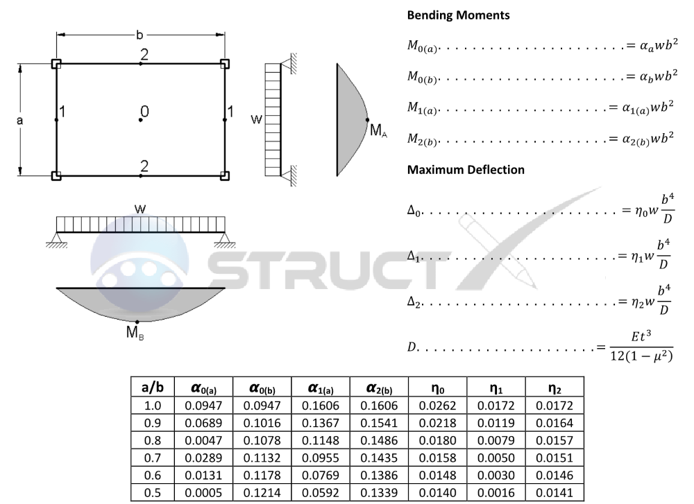
The deflection equation of a plate is a mathematical equation that describes the deflection of a plate under load. The equation takes into account the material properties of the plate, such as its Young's modulus and Poisson's ratio, as well as the geometry of the plate and the boundary conditions. The deflection equation is typically used to calculate the maximum deflection of the plate, which is an important consideration in engineering design.
Derivation of the Deflection Equation
The derivation of the deflection equation involves the use of partial differential equations and boundary value problems. The equation is derived by applying the principle of minimum potential energy to the plate, which states that the total potential energy of the plate is minimized when it is in equilibrium. The resulting equation is a fourth-order partial differential equation that describes the deflection of the plate. Some key steps in the derivation include:
- Assuming a small deflection of the plate, which allows for the use of linear elasticity theory
- Using the stress-strain relationships to express the stresses in the plate in terms of the strains
- Applying the principle of virtual work to derive the equilibrium equations for the plate
Types of Plates and Their Deflection Equations
There are several types of plates, each with its own deflection equation. Some common types of plates include rectangular plates, circular plates, and annular plates. The deflection equation for each type of plate depends on the boundary conditions and the load applied to the plate. For example, a simply supported rectangular plate has a deflection equation that is given by the Navier solution, while a clamped circular plate has a deflection equation that is given by the Bessel function. Some key characteristics of different types of plates include:
- Rectangular plates: have a deflection equation that is a two-dimensional partial differential equation
- Circular plates: have a deflection equation that is a one-dimensional partial differential equation in terms of the radial distance
- Annular plates: have a deflection equation that is a two-dimensional partial differential equation with mixed boundary conditions
Effects of Material Properties on Deflection
The material properties of a plate, such as its Young's modulus and Poisson's ratio, have a significant effect on its deflection. For example, a plate with a high Young's modulus will have a smaller deflection than a plate with a low Young's modulus. The Poisson's ratio also affects the deflection of the plate, with a higher Poisson's ratio resulting in a larger deflection. Some key effects of material properties on deflection include:
- Young's modulus: affects the stiffness of the plate and therefore its deflection
- Poisson's ratio: affects the lateral strain of the plate and therefore its deflection
- Density: affects the mass of the plate and therefore its dynamic response
Applications of the Deflection Equation
The deflection equation of a plate has a wide range of applications in engineering design. Some common applications include structural analysis, mechanical design, and aerospace engineering. The deflection equation is used to calculate the maximum deflection of a plate, which is an important consideration in design. Some key applications of the deflection equation include:
- Structural analysis: uses the deflection equation to calculate the stresses and strains in a plate
- Mechanical design: uses the deflection equation to calculate the deflection of a plate under load
- Aerospace engineering: uses the deflection equation to calculate the deflection of a plate under aerodynamic loads
Numerical Methods for Solving the Deflection Equation
There are several numerical methods that can be used to solve the deflection equation of a plate. Some common methods include the finite element method, the finite difference method, and the boundary element method. These methods involve discretizing the plate into a mesh of elements or nodes, and then solving the resulting system of equations. Some key advantages of numerical methods include:
- Finite element method: can handle complex geometries and nonlinear material behavior
- Finite difference method: can handle large deformations and dynamic problems
- Boundary element method: can handle infinite domains and mixed boundary conditions
What is the normal stress on a plate?
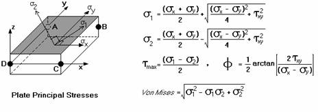
The normal stress on a plate is a measure of the force per unit area that is applied to the plate in a direction perpendicular to its surface. This type of stress is also known as pressure or normal pressure. It is an important concept in mechanics and engineering, as it can affect the deformation and failure of the plate.
Definition of Normal Stress
The normal stress on a plate is defined as the force applied to the plate divided by the area of the plate. It is a measure of the pressure exerted on the plate and is typically measured in units of pascals (Pa) or pounds per square inch (psi). The normal stress on a plate can be calculated using the following formula: σ = F/A, where σ is the normal stress, F is the force applied to the plate, and A is the area of the plate.
- The force applied to the plate can be due to various reasons, such as weight, friction, or external loads.
- The area of the plate is an important factor in determining the normal stress, as a larger area will result in a lower normal stress.
- The material properties of the plate, such as its elasticity and strength, can also affect the normal stress and the resulting deformation or failure of the plate.
Types of Normal Stress
There are several types of normal stress that can occur on a plate, including tensile stress, compressive stress, and shear stress. Tensile stress occurs when the plate is stretched or pulled, while compressive stress occurs when the plate is compressed or squeezed. Shear stress occurs when the plate is subjected to a force that causes it to deform by sliding or rotating.
- Tensile stress can cause the plate to elongate or fail if the force applied is too great.
- Compressive stress can cause the plate to shorten or buckle if the force applied is too great.
- Shear stress can cause the plate to deform or fail if the force applied is too great, and can also cause the plate to rotate or slide.
Effects of Normal Stress on a Plate
The normal stress on a plate can have several effects, including deformation, failure, and damage. The deformation of the plate can be elastic or plastic, depending on the material properties of the plate and the magnitude of the normal stress. The failure of the plate can occur due to fracture, yielding, or buckling, and can be catastrophic or gradual.
- The deformation of the plate can be reversible or irreversible, depending on the material properties of the plate and the magnitude of the normal stress.
- The failure of the plate can be sudden or gradual, depending on the material properties of the plate and the magnitude of the normal stress.
- The damage to the plate can be minor or major, depending on the material properties of the plate and the magnitude of the normal stress.
Measurement of Normal Stress on a Plate
The normal stress on a plate can be measured using various techniques, including strain gauges, load cells, and pressure sensors. These techniques can provide accurate and reliable measurements of the normal stress on the plate, and can be used to monitor and control the stress on the plate.
- Strain gauges can be used to measure the deformation of the plate and calculate the normal stress.
- Load cells can be used to measure the force applied to the plate and calculate the normal stress.
- Pressure sensors can be used to measure the pressure exerted on the plate and calculate the normal stress.
Applications of Normal Stress on a Plate
The normal stress on a plate has several applications in engineering and industry, including design, analysis, and testing of structures and machinery. The normal stress on a plate can be used to predict the behavior of the plate under various loading conditions, and can be used to optimize the design of the plate for maximum strength and minimum weight.
- The design of the plate can be optimized using finite element analysis and computational fluid dynamics.
- The analysis of the plate can be performed using classical mechanics and material science.
- The testing of the plate can be performed using experimental mechanics and materials testing.
Frequently Asked Questions (FAQs)
What is the Circular Plate Edges Clamped Uniform Load Equation and Calculator?
The Circular Plate Edges Clamped Uniform Load Equation and Calculator is a mathematical tool used to calculate the deflection and stress of a circular plate with clamped edges under a uniform load. The equation takes into account the plate's material properties, such as its modulus of elasticity and Poisson's ratio, as well as the load's magnitude and distribution. The calculator provides a quick and easy way to determine the maximum deflection and stress in the plate, allowing engineers to design and optimize their structures with accuracy and efficiency. The equation is based on the theory of plates, which assumes that the plate is thin and uniformly loaded, and that the edges are clamped or fixed. By using this equation and calculator, engineers can ensure that their designs meet the required safety and performance standards.
How does the Circular Plate Edges Clamped Uniform Load Equation and Calculator work?
The Circular Plate Edges Clamped Uniform Load Equation and Calculator works by solving the partial differential equation that governs the deflection of a circular plate under a uniform load. The equation is based on the biharmonic equation, which is a fourth-order differential equation that describes the bending and twisting of a plate. The calculator uses numerical methods to solve the equation, taking into account the boundary conditions imposed by the clamped edges. The calculator also allows users to input the plate's dimensions, material properties, and load parameters, and then calculates the maximum deflection and stress in the plate. The calculator uses advanced algorithms to ensure that the calculations are accurate and efficient, and provides a user-friendly interface that makes it easy to use and understand. By using this calculator, engineers can save time and reduce errors in their designs, and can focus on optimizing their structures for performance and safety.
What are the advantages of using the Circular Plate Edges Clamped Uniform Load Equation and Calculator?
The Circular Plate Edges Clamped Uniform Load Equation and Calculator has several advantages that make it a valuable tool for engineers. One of the main advantages is its accuracy, which is ensured by the use of advanced numerical methods and rigorous mathematical formulations. The calculator is also user-friendly, with a simple and intuitive interface that makes it easy to input parameters and obtain results. Another advantage is its efficiency, which allows engineers to save time and reduce errors in their designs. The calculator also provides a comprehensive analysis of the plate's behavior, including the maximum deflection and stress, which allows engineers to optimize their designs for performance and safety. Additionally, the calculator is flexible, allowing users to input a wide range of parameters and conditions, and to customize the calculations to suit their specific needs. By using this calculator, engineers can ensure that their designs meet the required standards and regulations, and can improve their overall design process.
What are the limitations and assumptions of the Circular Plate Edges Clamped Uniform Load Equation and Calculator?
The Circular Plate Edges Clamped Uniform Load Equation and Calculator has several limitations and assumptions that users should be aware of. One of the main limitations is the assumption of a thin plate, which may not be valid for thicker plates or plates with complex geometries. The calculator also assumes that the load is uniform and distributed evenly over the plate, which may not be the case in real-world applications. Additionally, the calculator assumes that the edges are clamped, which may not be the case in structures with different boundary conditions. The calculator also neglects the effects of shear deformation and rotary inertia, which may be significant in high-frequency applications or structures with high aspect ratios. Furthermore, the calculator is based on the theory of plates, which is a simplified model that may not capture all the complexities of real-world structures. By understanding these limitations and assumptions, engineers can use the calculator with caution and judgment, and can interpret the results in the context of their specific design problem.
Comparte nuestro Conocimiento
Charles DeLadurantey
Six Sigma Master Black Belt & Lean Six Sigma Master Black Belt
Writer at The Council of Six Sigma Certification
Lean Six Sigma expert serving customers for over 20 years. Proven leader of change and bottom line improvement for clients and employers nationwide.


Entradas Relacionadas