
Beam Three Supports Concentrated Load Formulas and Calculator

Beam Three Supports Concentrated Load Formulas and Calculator is a valuable resource for engineers and architects. It provides a comprehensive collection of formulas and a calculator to determine the reactions and bending moments in a beam with three supports and a concentrated load. This article will outline the key formulas and calculations involved, and demonstrate how to use the calculator to solve real-world problems. The calculator is designed to simplify the process, saving time and reducing errors. It is an essential tool for designing and analyzing beams in various engineering applications. Accurate calculations are crucial.
- Understanding Beam Three Supports Concentrated Load Formulas and Calculator
- How do you calculate beam load capacity formula?
- How to calculate load on a simply supported beam?
- How do you calculate the size of a support beam?
- What is the formula for uniformly distributed load on a beam?
-
Frequently Asked Questions (FAQs)
- What is the significance of beam three supports concentrated load formulas and calculator in engineering?
- How do beam three supports concentrated load formulas and calculator work?
- What are the advantages of using beam three supports concentrated load formulas and calculator?
- What are the common applications of beam three supports concentrated load formulas and calculator?
Understanding Beam Three Supports Concentrated Load Formulas and Calculator
When dealing with structural analysis, particularly for beams under load, understanding how different types of loading and support conditions affect the beam's behavior is crucial. A beam three supports concentrated load scenario involves a beam that is supported at three points and subjected to a concentrated load at a specific point. This scenario is critical in engineering as it helps in designing structures that can withstand various types of loads without failing.
Introduction to Beam Three Supports Concentrated Load
The beam three supports concentrated load problem is a fundamental concept in mechanics of materials and structural analysis. It involves determining the reactions at the supports, the shear force diagram, the bending moment diagram, and the deflection of the beam. This analysis is essential for ensuring that the beam can support the applied load without excessive stress or deflection.
Formulas for Beam Three Supports Concentrated Load
For a beam with three supports and a concentrated load, several formulas can be applied to calculate the reactions at the supports, shear forces, and bending moments. These formulas are derived from the principles of static equilibrium and the beam's geometric properties. The calculation involves determining the moment of inertia of the beam's cross-section, the elastic modulus of the material, and applying the superposition principle for multiple loads.
Calculator for Beam Three Supports Concentrated Load
A calculator for beam three supports concentrated load can be a software tool or a spreadsheet that uses the formulas derived from beam theory to calculate the reactions, shear forces, bending moments, and deflections. These calculators simplify the process by allowing users to input the beam's dimensions, material properties, load magnitude, and position, and then calculate the required values.
Applications of Beam Three Supports Concentrated Load Analysis
The analysis of a beam with three supports under a concentrated load has numerous applications in civil, mechanical, and aerospace engineering. It is used in the design of bridges, buildings, machinery, and aircraft structures where the load-bearing capacity and stability of beams are critical. This type of analysis ensures that structures can withstand various loads, including static loads and dynamic loads, without failure.
Limitations and Considerations
When applying the formulas and calculators for a beam three supports concentrated load, several limitations and considerations must be taken into account. These include the assumption of a linear elastic material behavior, the neglect of shear deformation, and the simplification of the load as a point load. Additionally, the analysis might need to consider boundary conditions, material nonlinearity, and dynamic effects for more complex scenarios.
| Parameter | Unit | Description |
|---|---|---|
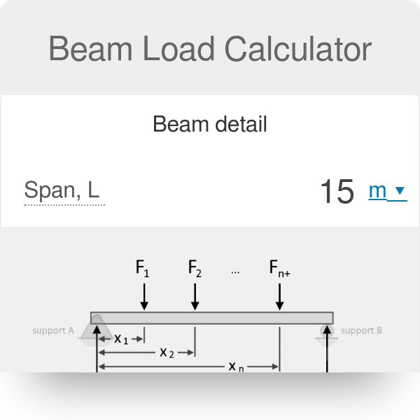
| Span Length | m | The distance between two adjacent supports. |
| Concentrated Load | N | A load applied at a single point on the beam. |
| Elastic Modulus | Pa | A measure of the stiffness of the beam material. |
| Moment of Inertia | m^4 | A geometric property of the beam's cross-section. |
How do you calculate beam load capacity formula?
To calculate the beam load capacity, you need to consider several factors, including the beam's material, size, and support conditions. The formula for calculating beam load capacity is typically based on the moment of inertia and the section modulus of the beam. The moment of inertia is a measure of the beam's resistance to bending, while the section modulus is a measure of the beam's ability to resist bending stress.
Understanding Beam Load Capacity Formula
The beam load capacity formula is used to determine the maximum load that a beam can support without failing. The formula takes into account the beam's length, width, and height, as well as the material's yield strength and ultimate strength. To calculate the beam load capacity, you need to know the following:
- The beam's dimensions, including its length, width, and height.
- The material's properties, including its yield strength and ultimate strength.
- The support conditions, including the type of supports and the distance between them.
Calculating Moment of Inertia
The moment of inertia is a critical factor in calculating the beam load capacity. It is calculated using the beam's cross-sectional area and the distance from the neutral axis to the extreme fibers. The moment of inertia is typically calculated using the following formula: I = (1/12) b h^3, where I is the moment of inertia, b is the beam's width, and h is the beam's height. To calculate the moment of inertia, you need to:
- Know the beam's dimensions, including its width and height.
- Understand the beam's cross-sectional area and the distance from the neutral axis to the extreme fibers.
- Use the formula to calculate the moment of inertia.
Calculating Section Modulus
The section modulus is another important factor in calculating the beam load capacity. It is calculated using the moment of inertia and the distance from the neutral axis to the extreme fibers. The section modulus is typically calculated using the following formula: S = I / c, where S is the section modulus, I is the moment of inertia, and c is the distance from the neutral axis to the extreme fibers. To calculate the section modulus, you need to:
- Know the moment of inertia and the distance from the neutral axis to the extreme fibers.
- Understand the beam's cross-sectional area and the beam's dimensions.
- Use the formula to calculate the section modulus.
Applying Beam Load Capacity Formula
To apply the beam load capacity formula, you need to know the beam's dimensions, the material's properties, and the support conditions. The formula is typically used to determine the maximum load that a beam can support without failing. To apply the formula, you need to:
- Know the beam's dimensions, including its length, width, and height.
- Understand the material's properties, including its yield strength and ultimate strength.
- Use the formula to calculate the beam load capacity.
Considerations for Beam Load Capacity
When calculating the beam load capacity, there are several considerations that need to be taken into account, including the beam's material, size, and support conditions. The beam's material can affect its strength and stiffness, while the size can affect its moment of inertia and section modulus. The support conditions can also affect the beam's load capacity, as different supports can provide different levels of restraint. To consider these factors, you need to:
- Understand the beam's material and its properties.
- Know the beam's dimensions and its support conditions.
- Use finite element analysis or other numerical methods to model the beam's behavior under different loads.
How to calculate load on a simply supported beam?
To calculate the load on a simply supported beam, you need to consider the weight of the beam itself, as well as any external loads that may be applied to it. This can include point loads, uniformly distributed loads, and moments. The beam's length, material, and cross-sectional area also play a crucial role in determining its load-carrying capacity.
Beam Load Calculations
The calculation of load on a simply supported beam involves determining the maximum bending moment and shear force that the beam can withstand. This can be done using formulas and equations that take into account the beam's geometry and material properties. For example, the maximum bending moment can be calculated using the formula: M = (w L^2) / 8, where M is the maximum bending moment, w is the uniformly distributed load, and L is the beam's length.
- Determine! the beam's length and material properties.
- Calculate the maximum bending moment using the formula: M = (w L^2) / 8.
- Calculate the maximum shear force using the formula: V = (w L) / 2.
Load Types and Applications
There are several types of loads that can be applied to a simply supported beam, including point loads, uniformly distributed loads, and moments. Each type of load requires a different calculation method to determine its effect on the beam. For example, a point load can be calculated using the formula: P = (2 M) / L, where P is the point load, M is the maximum bending moment, and L is the beam's length.
- Identify the type of load being applied to the beam.
- Determine the magnitude of the load.
- Calculate the effect of the load on the beam using the appropriate formula.
Simply Supported Beam Boundary Conditions
A simply supported beam has two supports, one at each end, which can be either pinned or roller supports. The boundary conditions of the beam must be taken into account when calculating the load. For example, a pinned support can resist moments, while a roller support cannot.
- Determine the type of supports being used.
- Identify the boundary conditions of the beam.
- Calculate the load using the appropriate formula and boundary conditions.
Material Properties and Beam Geometry
The material properties and beam geometry play a crucial role in determining the load-carrying capacity of a simply supported beam. The beam's cross-sectional area, moment of inertia, and young's modulus must be taken into account when calculating the load.
- Determine the material properties of the beam.
- Calculate the beam's cross-sectional area and moment of inertia.
- Use the material properties and beam geometry to calculate the load.
Load Calculation Formulas and Equations
There are several formulas and equations that can be used to calculate the load on a simply supported beam, including the formula for maximum bending moment: M = (w L^2) / 8, and the formula for maximum shear force: V = (w L) / 2. These formulas and equations must be used in conjunction with the beam's material properties and geometry to determine the load-carrying capacity.
- Identify the formula or equation being used to calculate the load.
- Plug in the values for the beam's length, material properties, and load.
- Solve for the load using the formula or equation.
How do you calculate the size of a support beam?
To calculate the size of a support beam, you need to consider several factors, including the load it will carry, the span of the beam, and the material it is made of. The calculation involves determining the bending moment and shear forces that the beam will experience, as well as the deflection and stress it will undergo. This requires the use of mathematical formulas and engineering principles, such as the beam theory and the stress-strain relationship.
Determining the Load and Span
To calculate the size of a support beam, you need to determine the load it will carry and the span of the beam. The load includes the weight of the structure, as well as any external forces that may be applied, such as wind loads or seismic loads. The span of the beam is the distance between the supports, and it affects the bending moment and shear forces that the beam will experience.
- The load is calculated by multiplying the weight of the structure by the load factor, which takes into account the type of load and the duration of the load.
- The span of the beam is measured from the center of one support to the center of the other support.
- The bending moment is calculated by multiplying the load by the span, and it is used to determine the size and material of the beam.
Calculating the Bending Moment and Shear Forces
The bending moment and shear forces are calculated using the beam theory, which takes into account the load, span, and boundary conditions of the beam. The bending moment is the torque that causes the beam to bend, while the shear forces are the forces that cause the beam to deform.
- The bending moment is calculated using the formula: M = (w L^2) / 8, where M is the bending moment, w is the load, and L is the span.
- The shear forces are calculated using the formula: V = (w L) / 2, where V is the shear force, w is the load, and L is the span.
- The bending moment and shear forces are used to determine the size and material of the beam, as well as the type of support required.
Selecting the Material and Size of the Beam
The material and size of the beam are selected based on the calculated loads and stresses, as well as the available materials and construction methods. The material properties, such as the strength, stiffness, and density, are used to determine the size and shape of the beam.
- The material is selected based on the required strength, stiffness, and durability, as well as the cost and availability.
- The size of the beam is determined using the formulas and charts provided in the design codes, such as the American Institute of Steel Construction (AISC) or the American Concrete Institute (ACI).
- The shape of the beam is determined based on the required moment of inertia and section modulus, as well as the available shapes and sizes.
Checking the Deflection and Stress
The deflection and stress of the beam are checked to ensure that they are within the allowable limits. The deflection is the vertical displacement of the beam under load, while the stress is the force per unit area that the beam experiences.
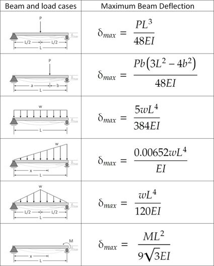
- The deflection is calculated using the formula: Δ = (w L^4) / (8 E I), where Δ is the deflection, w is the load, L is the span, E is the modulus of elasticity, and I is the moment of inertia.
- The stress is calculated using the formula: σ = (M c) / I, where σ is the stress, M is the bending moment, c is the distance from the neutral axis to the extreme fiber, and I is the moment of inertia.
- The deflection and stress are checked against the allowable limits provided in the design codes, such as the American Institute of Steel Construction (AISC) or the American Concrete Institute (ACI).
Designing the Support System
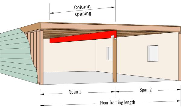
The support system is designed to provide the required support to the beam, while also ensuring that it is stable and secure. The support system includes the foundations, columns, and beams that provide the vertical and lateral support to the structure.
- The foundations are designed to transfer the loads from the structure to the ground, while also providing the required stability and support.
- The columns are designed to provide the vertical support to the beams and slabs, while also ensuring that they are stable and secure.
- The beams are designed to provide the lateral support to the structure, while also ensuring that they are stable and secure.
What is the formula for uniformly distributed load on a beam?
The formula for a uniformly distributed load on a beam is given by the equation: w = P/L, where w is the uniform load per unit length, P is the total load, and L is the length of the beam. This formula is used to calculate the load intensity along the length of the beam.
Calculation of Uniformly Distributed Load
The calculation of a uniformly distributed load on a beam involves determining the total load and the length of the beam. The total load can be calculated by multiplying the area of the surface by the weight density of the material. The length of the beam is typically given in the problem statement. The formula can be applied to various types of beams, including simply supported beams and cantilever beams.
- The total load is calculated by multiplying the area of the surface by the weight density of the material.
- The length of the beam is typically given in the problem statement.
- The formula can be applied to various types of beams, including simply supported beams and cantilever beams.
Types of Beams with Uniformly Distributed Load
There are several types of beams that can have a uniformly distributed load, including simply supported beams, cantilever beams, and overhanging beams. Each type of beam has its own unique characteristics and boundary conditions. The uniform load can be applied to the entire length of the beam or to a portion of it.
- Simply supported beams have two supports at each end and can have a uniform load applied to the entire length.
- Cantilever beams have one fixed support and can have a uniform load applied to the entire length.
- Overhanging beams have two supports and a portion of the beam extends beyond one of the supports.
Application of Uniformly Distributed Load Formula
The formula for a uniformly distributed load on a beam has numerous applications in structural engineering and construction. It is used to design and analyze beams, girders, and other structural members. The formula can be applied to various types of loads, including dead loads, live loads, and environmental loads.
- The formula is used to design and analyze beams and girders in bridges and buildings.
- The formula can be applied to various types of loads, including dead loads, live loads, and environmental loads.
- The uniform load formula is an essential tool for structural engineers and architects.
Importance of Uniformly Distributed Load in Structural Engineering
The concept of uniformly distributed load is crucial in structural engineering as it helps to determine the stress and strain on beams and other structural members. The uniform load formula is used to calculate the maximum bending moment and shear force on a beam, which are essential for designing safe and stable structures.
- The uniform load formula is used to calculate the maximum bending moment and shear force on a beam.
- The uniform load concept is essential for designing safe and stable structures.
- The uniform load formula is used in conjunction with other structural analysis techniques, such as finite element method.
Assumptions and Limitations of Uniformly Distributed Load Formula
The formula for a uniformly distributed load on a beam is based on several assumptions and has some limitations. The formula assumes that the load is uniformly distributed along the length of the beam and that the beam is prismatic. The formula also assumes that the material is homogeneous and isotropic.
- The formula assumes that the load is uniformly distributed along the length of the beam.
- The formula assumes that the beam is prismatic and has a constant cross-sectional area.
- The formula also assumes that the material is homogeneous and isotropic.
Frequently Asked Questions (FAQs)
What is the significance of beam three supports concentrated load formulas and calculator in engineering?
The beam three supports concentrated load formulas and calculator is a crucial tool in the field of engineering, particularly in the design and analysis of beams and structural systems. It provides a simple and efficient way to calculate the reactions, shear forces, and bending moments at specific points along a beam that is subjected to a concentrated load and supported by three supports. This information is essential for determining the stability and safety of the structure, as well as for selecting the appropriate materials and dimensions for the beam. By using the formulas and calculator, engineers can quickly and accurately calculate the forces and moments acting on the beam, allowing them to optimize the design and ensure that it can withstand the expected loads and stresses.
How do beam three supports concentrated load formulas and calculator work?
The beam three supports concentrated load formulas and calculator work by using a set of mathematical equations to calculate the reactions, shear forces, and bending moments at specific points along the beam. These equations take into account the magnitude and location of the concentrated load, as well as the position and type of the supports. The calculator uses these equations to provide a step-by-step solution to the problem, allowing users to input the given values and calculate the unknown quantities. The formulas and calculator are based on the principles of statics and mechanics of materials, and are widely used in the field of civil engineering, mechanical engineering, and structural engineering. By using the formulas and calculator, users can quickly and accurately calculate the forces and moments acting on the beam, and determine the stability and safety of the structure.
What are the advantages of using beam three supports concentrated load formulas and calculator?
The beam three supports concentrated load formulas and calculator offer several advantages over traditional methods of beam analysis. One of the main advantages is the speed and accuracy of the calculations, which allows users to quickly and easily calculate the reactions, shear forces, and bending moments at specific points along the beam. Another advantage is the ease of use, as the calculator provides a user-friendly interface that allows users to input the given values and calculate the unknown quantities with minimal effort. The formulas and calculator also provide a high degree of accuracy, which is essential for ensuring the stability and safety of the structure. Additionally, the formulas and calculator can be used to analyze a wide range of beam configurations and loading conditions, making them a versatile and powerful tool for engineers and designers.
What are the common applications of beam three supports concentrated load formulas and calculator?
The beam three supports concentrated load formulas and calculator have a wide range of applications in the field of engineering, particularly in the design and analysis of beams and structural systems. One of the most common applications is in the design of bridges, where the formulas and calculator are used to calculate the reactions, shear forces, and bending moments at specific points along the bridge. Another common application is in the design of buildings, where the formulas and calculator are used to calculate the forces and moments acting on the beams and columns. The formulas and calculator are also used in the design of machinery and equipment, where they are used to calculate the stresses and strains acting on the components. Additionally, the formulas and calculator are used in research and development, where they are used to model and simulate the behavior of complex systems and structures.
Deja una respuesta
Entradas Relacionadas