
Beam Deflection Calculator for Fixed Ends Moment Applied

The calculation of beam deflection is a crucial aspect of structural engineering, particularly when dealing with fixed-end beams subjected to moment applications. Beam deflection calculators are essential tools for determining the degree of deformation that occurs in a beam under specific loading conditions. A beam deflection calculator for fixed ends with moment applied simplifies the complex calculations involved, providing engineers with a reliable means of evaluating beam behavior and making informed design decisions to ensure structural integrity and safety. This calculator is based on established engineering principles and formulas.
- Beam Deflection Calculator for Fixed Ends Moment Applied
- What is the formula for the deflection of a beam fixed at both ends?
- How to calculate moment in fixed beam?
- What is BM and SF in fixed beam?
-
Frequently Asked Questions (FAQs)
- What is the purpose of the Beam Deflection Calculator for Fixed Ends Moment Applied?
- How does the Beam Deflection Calculator for Fixed Ends Moment Applied account for the moment applied?
- What are the limitations of the Beam Deflection Calculator for Fixed Ends Moment Applied?
- How can I use the Beam Deflection Calculator for Fixed Ends Moment Applied in practice?
Beam Deflection Calculator for Fixed Ends Moment Applied
The Beam Deflection Calculator for Fixed Ends Moment Applied is a tool used to calculate the deflection of a beam under a specific load. This calculator is particularly useful for engineers and designers who need to determine the deflection of a beam under various loads, including fixed ends moment applied. The calculator takes into account the length of the beam, the moment applied, and the material properties of the beam to calculate the deflection.
Understanding Beam Deflection
Beam deflection refers to the bending or deformation of a beam under a load. This can be caused by a variety of factors, including external loads, internal stresses, and support conditions. The Beam Deflection Calculator for Fixed Ends Moment Applied uses the following formula to calculate the deflection: δ = (M L^2) / (8 E I), where δ is the deflection, M is the moment applied, L is the length of the beam, E is the modulus of elasticity, and I is the moment of inertia.
Key Parameters in Beam Deflection Calculation
The Beam Deflection Calculator for Fixed Ends Moment Applied requires several key parameters to calculate the deflection. These include:
| Parameter | Description |
|---|---|
| Length | The length of the beam |
| Moment | The moment applied to the beam |
| Modulus of Elasticity | A measure of the beam's stiffness |
| Moment of Inertia | A measure of the beam's resistance to bending |
Applications of Beam Deflection Calculator
The Beam Deflection Calculator for Fixed Ends Moment Applied has a wide range of applications in engineering and design. It can be used to calculate the deflection of beams in buildings, bridges, and other structures. The calculator can also be used to determine the structural integrity of a beam under various loads.
Advantages of Using Beam Deflection Calculator
The Beam Deflection Calculator for Fixed Ends Moment Applied has several advantages over traditional methods of calculating beam deflection. These include:
Accuracy: The calculator provides accurate results, eliminating the need for manual calculations and reducing the risk of human error.
Speed: The calculator can quickly calculate the deflection of a beam, saving time and increasing productivity.
Ease of use: The calculator is easy to use, requiring only a few input parameters to calculate the deflection.
Limitations and Assumptions of Beam Deflection Calculator
The Beam Deflection Calculator for Fixed Ends Moment Applied has several limitations and assumptions that must be considered. These include:
Assumes a linear elastic response: The calculator assumes that the beam will respond linearly to the applied load, which may not be the case for all materials.
Ignores other loads: The calculator only considers the moment applied to the beam and ignores other loads, such as axial loads and torsional loads.
Assumes a simple support condition: The calculator assumes a simple support condition, which may not be the case for all beams.
What is the formula for the deflection of a beam fixed at both ends?
The formula for the deflection of a beam fixed at both ends is given by the equation: δ = (W L^3) / (192 E I), where δ is the deflection, W is the load applied, L is the length of the beam, E is the modulus of elasticity, and I is the moment of inertia of the beam. This equation is used to calculate the maximum deflection of a beam that is fixed at both ends and subjected to a uniformly distributed load.
Understanding the Formula Components
The formula for the deflection of a beam fixed at both ends involves several key components, including the load, length, modulus of elasticity, and moment of inertia. These components are crucial in determining the amount of deflection that occurs in the beam. The formula can be broken down into the following components:
- The load (W) is the force applied to the beam, which can be either a point load or a uniformly distributed load.
- The length (L) is the distance between the two fixed ends of the beam.
- The modulus of elasticity (E) is a measure of the beam's ability to resist deformation under stress.
Calculating the Moment of Inertia
The moment of inertia (I) is a critical component in the formula for the deflection of a beam fixed at both ends. It is calculated based on the cross-sectional area and shape of the beam. The moment of inertia can be calculated using the following formula: I = (b h^3) / 12, where b is the width of the beam and h is the height of the beam. The moment of inertia can be calculated for different shapes, such as:
- Rectangular beams, where I = (b h^3) / 12.
- Circular beams, where I = (π d^4) / 64.
- I-beams, where I = (b h^3) / 12 - (b (h - 2 t)^3) / 12.
Assumptions and Limitations
The formula for the deflection of a beam fixed at both ends is based on several assumptions and limitations, including:
- The beam is homogeneous and isotropic, meaning that its properties are the same throughout and in all directions.
- The beam is subjected to a static load, meaning that the load is applied slowly and does not change over time.
- The beam is linearly elastic, meaning that it behaves in a linear and elastic manner under stress.
Real-World Applications
The formula for the deflection of a beam fixed at both ends has numerous real-world applications, including:
- Building design, where the deflection of beams is critical in ensuring the structural integrity of buildings.
- Bridge design, where the deflection of beams is crucial in ensuring the safety and stability of bridges.
- Machine design, where the deflection of beams is important in ensuring the accuracy and precision of machines.
Common Mistakes and Errors
When using the formula for the deflection of a beam fixed at both ends, it is common to encounter mistakes and errors, including:
- Incorrect units, where the units of measurement are not consistent throughout the calculation.
- Incorrect assumptions, where the assumptions made about the beam's properties and behavior are not valid.
- Numerical errors, where the calculations are not performed accurately, resulting in incorrect results.
How to calculate moment in fixed beam?

To calculate the moment in a fixed beam, you need to understand the forces acting on the beam and the reactions at the supports. The moment is a measure of the torque or rotational force that causes the beam to rotate or deform. It is calculated by multiplying the force by the distance from the point of application to the point where the moment is being calculated.
Understanding the Types of Loads
To calculate the moment in a fixed beam, you need to understand the types of loads that are applied to the beam. The loads can be point loads, uniformly distributed loads, or linearly varying loads. The moment is calculated differently for each type of load. For example, for a point load, the moment is calculated by multiplying the load by the distance from the point of application to the point where the moment is being calculated.
- The point load is a concentrated load that is applied at a single point on the beam.
- The uniformly distributed load is a load that is applied uniformly along the length of the beam.
- The linearly varying load is a load that varies linearly along the length of the beam.
Calculating the Reactions at the Supports
To calculate the moment in a fixed beam, you need to calculate the reactions at the supports. The reactions are the forces that the supports exert on the beam to prevent it from moving or rotating. The reactions can be calculated using the equilibrium equation and the moment equilibrium equation.
- The equilibrium equation states that the sum of the forces in any direction is equal to zero.
- The moment equilibrium equation states that the sum of the moments about any point is equal to zero.
- The reactions at the supports can be calculated by solving the equilibrium equation and the moment equilibrium equation simultaneously.
Determining the Moment Diagram
The moment diagram is a graphical representation of the moment along the length of the beam. To determine the moment diagram, you need to calculate the moment at each point along the beam. The moment can be calculated using the formula: M = F d, where M is the moment, F is the force, and d is the distance from the point of application to the point where the moment is being calculated.
- The moment diagram shows the variation of the moment along the length of the beam.
- The moment diagram can be used to determine the maximum moment and the minimum moment along the beam.
- The moment diagram can be used to design the beam to withstand the loads and stresses.
Calculating the Maximum Moment
The maximum moment is the largest moment that occurs along the length of the beam. To calculate the maximum moment, you need to calculate the moment at each point along the beam and find the maximum value. The maximum moment occurs at the point where the shear force is zero.
- The maximum moment is used to design the beam to withstand the loads and stresses.
- The maximum moment is used to determine the minimum required section of the beam.
- The maximum moment is used to determine the minimum required reinforcement in a reinforced concrete beam.
Applying the Moment Formula
The moment formula is M = F d, where M is the moment, F is the force, and d is the distance from the point of application to the point where the moment is being calculated. To apply the moment formula, you need to know the force and the distance. The force can be a point load, a uniformly distributed load, or a linearly varying load.
- The moment formula can be used to calculate the moment at any point along the beam.
- The moment formula can be used to calculate the maximum moment and the minimum moment along the beam.
- The moment formula is a fundamental concept in statics and is used to analyze and design beams and other structures.
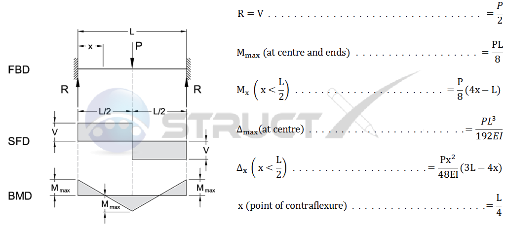
What is BM and SF in fixed beam?

BM and SF in a fixed beam refer to the Bending Moment and Shear Force respectively. These are two fundamental concepts in structural analysis and are used to determine the internal forces that act on a beam when it is subjected to external loads.
Introduction to Bending Moment and Shear Force
The Bending Moment (BM) is a measure of the tendency of a beam to bend or flex under an external load, while the Shear Force (SF) is a measure of the tendency of a beam to deform by sliding or shearing. These forces are critical in determining the stress and strain on a beam, and are used to design and analyze beams in various engineering applications. Some key points to note about BM and SF include:
- The Bending Moment is typically measured in units of force times distance (e.g. Newton-meters or foot-pounds)
- The Shear Force is typically measured in units of force (e.g. Newtons or pounds)
- Both BM and SF can vary along the length of a beam, depending on the external loads and the beam's supports
Calculating Bending Moment and Shear Force
Calculating the Bending Moment and Shear Force in a fixed beam involves using various mathematical formulas and techniques. These calculations typically involve integrating the external loads and reactions over the length of the beam, and can be complex and time-consuming. Some key steps in calculating BM and SF include:
- Determining the external loads acting on the beam, including point loads, distributed loads, and moments
- Calculating the reactions at the beam's supports, including the support forces and moments
- Using integration to calculate the Bending Moment and Shear Force along the length of the beam
Types of Beams and Loading Conditions
Different types of beams and loading conditions can affect the Bending Moment and Shear Force in a fixed beam. For example, a simply supported beam will have a different BM and SF diagram than a fixed-fixed beam. Additionally, point loads, distributed loads, and moments can all affect the BM and SF in a beam. Some key types of beams and loading conditions include:
- Simply supported beams, which have two supports and are free to rotate at the supports
- Fixed-fixed beams, which have two fixed supports and are not free to rotate at the supports
- Cantilever beams, which have one fixed support and are free to rotate at the other end
Real-World Applications of BM and SF
The Bending Moment and Shear Force are critical in a wide range of real-world applications, including building design, bridge construction, and mechanical engineering. These forces are used to design and analyze beams, columns, and other structural elements, and are essential for ensuring the safety and stability of structures. Some key real-world applications include:
- Building frames, which use beams and columns to support floors and roofs
- Bridge design, which uses beams and cables to support roadways and pedestrian walkways
- Mechanical systems, which use beams and shafts to transmit forces and moments
Importance of BM and SF in Structural Analysis
The Bending Moment and Shear Force are essential components of structural analysis, which is the process of determining the stresses and strains on a structure due to external loads. These forces are used to design and analyze structures, and are critical for ensuring the safety and stability of buildings, bridges, and other structures. Some key reasons why BM and SF are important include:
- Structural integrity, which requires that the Bending Moment and Shear Force be within the design limits of the structure
- Safety, which requires that the structure be able to withstand external loads and forces without failing
- Stability, which requires that the structure be able to resist deformation and collapse due to external loads
Frequently Asked Questions (FAQs)
What is the purpose of the Beam Deflection Calculator for Fixed Ends Moment Applied?
The Beam Deflection Calculator for Fixed Ends Moment Applied is a tool designed to calculate the deflection and stress of a beam with fixed ends when a moment is applied. This calculator is particularly useful for engineers and architects who need to determine the structural integrity of a beam under various loads. By using this calculator, users can input the beam's length, moment of inertia, young's modulus, and the applied moment, and the calculator will output the maximum deflection and stress of the beam. This information is crucial in ensuring that the beam can withstand the applied loads without failing or collapsing. The calculator takes into account the boundary conditions of the beam, which in this case are fixed ends, meaning that the beam is restrained from rotating or translating at both ends.
How does the Beam Deflection Calculator for Fixed Ends Moment Applied account for the moment applied?
The Beam Deflection Calculator for Fixed Ends Moment Applied accounts for the moment applied by using the beam theory equations, which relate the moment and shear force to the deflection and slope of the beam. The calculator uses the formula for the deflection of a beam with fixed ends, which is a function of the applied moment, beam length, and moment of inertia. The calculator also takes into account the sign of the applied moment, which can be either positive or negative, depending on the direction of the moment. The calculator uses this information to determine the maximum deflection and stress of the beam, which is essential in ensuring that the beam can withstand the applied loads. The calculator also provides a graphical representation of the deflection and moment diagrams, which can be used to visualize the behavior of the beam under the applied loads.
What are the limitations of the Beam Deflection Calculator for Fixed Ends Moment Applied?
The Beam Deflection Calculator for Fixed Ends Moment Applied has several limitations that users should be aware of. One of the main limitations is that the calculator assumes a simple beam theory, which may not be accurate for complex beam structures or non-uniform beams. Additionally, the calculator assumes that the material properties of the beam are linear elastic, which may not be the case for non-linear materials. The calculator also does not account for dynamic loads or impact loads, which can be important in certain applications. Furthermore, the calculator assumes that the beam is perfectly fixed at both ends, which may not be the case in reality. Users should be aware of these limitations and use the calculator accordingly, and consult with a qualified engineer if they are unsure about the accuracy of the results.
How can I use the Beam Deflection Calculator for Fixed Ends Moment Applied in practice?
The Beam Deflection Calculator for Fixed Ends Moment Applied can be used in practice by engineers and architects to design and analyze beam structures. For example, a structural engineer designing a bridge may use the calculator to determine the deflection and stress of the bridge's deck beams under various traffic loads. A mechanical engineer designing a machine may use the calculator to determine the deflection and stress of the machine's frame under various operating loads. The calculator can also be used to optimize the design of a beam structure by minimizing the weight and cost of the structure while ensuring that it can withstand the applied loads. Users can also use the calculator to compare the results of different design scenarios, and to iterate on the design until the desired performance is achieved. By using the calculator in practice, users can ensure that their designs are safe, efficient, and cost-effective.
Deja una respuesta
Entradas Relacionadas