
Beam Deflection and Stress Equations Calculator for Beam with Ends Overhanging Supports and a Two Equal Loads applied at Symmetrical Locations

The calculation of beam deflection and stress is a crucial aspect of structural engineering, particularly in scenarios where beams are subjected to various load configurations. A beam with ends overhanging supports and two equal loads applied at symmetrical locations presents a complex loading condition. To accurately determine the deflection and stress at any point along the beam, a reliable calculator is essential. This article introduces a calculator specifically designed to solve beam deflection and stress equations for such a beam configuration, providing engineers with a valuable tool for efficient and accurate calculations. Its usage greatly simplifies analysis.
- Beam Deflection and Stress Equations Calculator for Beam with Ends Overhanging Supports and a Two Equal Loads applied at Symmetrical Locations
-
What is the formula for deflection of an overhang beam?
- Understanding the Formula for Deflection of an Overhang Beam
- Calculating the Moment of Inertia for an Overhang Beam
- Applying the Formula for Deflection of an Overhang Beam
- Assumptions and Limitations of the Formula for Deflection of an Overhang Beam
- Real-World Applications of the Formula for Deflection of an Overhang Beam
- What is the formula for the deflection of a beam fixed at both ends?
- What is the formula for bending a beam?
- How do you calculate the stress of a beam?
-
Frequently Asked Questions (FAQs)
- What is the purpose of the Beam Deflection and Stress Equations Calculator for Beam with Ends Overhanging Supports and a Two Equal Loads applied at Symmetrical Locations?
- How does the Beam Deflection and Stress Equations Calculator for Beam with Ends Overhanging Supports and a Two Equal Loads applied at Symmetrical Locations work?
- What are the advantages of using the Beam Deflection and Stress Equations Calculator for Beam with Ends Overhanging Supports and a Two Equal Loads applied at Symmetrical Locations?
- What are the limitations of the Beam Deflection and Stress Equations Calculator for Beam with Ends Overhanging Supports and a Two Equal Loads applied at Symmetrical Locations?
Beam Deflection and Stress Equations Calculator for Beam with Ends Overhanging Supports and a Two Equal Loads applied at Symmetrical Locations
The beam deflection and stress equations calculator is a useful tool for engineers and designers to calculate the deflection and stress of a beam with ends overhanging supports and two equal loads applied at symmetrical locations. This calculator uses the Euler-Bernoulli beam theory to calculate the deflection and stress of the beam. The calculator takes into account the length, width, and thickness of the beam, as well as the young's modulus and poisson's ratio of the material.
Introduction to Beam Deflection and Stress Equations
Beam deflection and stress equations are used to calculate the deflection and stress of a beam under various loading conditions. The deflection of a beam is the amount of bending or deformation that occurs when a load is applied, while the stress is the internal force that is distributed within the beam. The beam deflection and stress equations are based on the Euler-Bernoulli beam theory, which assumes that the beam is straight, uniform, and symmetric.
Assumptions and Limitations of the Calculator
The beam deflection and stress equations calculator makes several assumptions and has limitations. The calculator assumes that the beam is straight, uniform, and symmetric, and that the loads are applied at symmetrical locations. The calculator also assumes that the young's modulus and poisson's ratio of the material are constant. The limitations of the calculator include the simplifications of the Euler-Bernoulli beam theory, which may not account for non-linear effects or large deflections.
Input Parameters for the Calculator
The beam deflection and stress equations calculator requires several input parameters, including the length, width, and thickness of the beam, as well as the young's modulus and poisson's ratio of the material. The calculator also requires the load and location of the loads. The following table shows the input parameters required by the calculator:
| Parameter | Unit | Description |
|---|---|---|
| Length | m | The length of the beam |
| Width | m | The width of the beam |
| Thickness | m | The thickness of the beam |
| Young's Modulus | Pa | The young's modulus of the material |
| Poisson's Ratio | - | The poisson's ratio of the material |
| Load | N | The load applied to the beam |
| Location | m | The location of the load |
Output Parameters for the Calculator
The beam deflection and stress equations calculator outputs several parameters, including the deflection and stress of the beam. The calculator also outputs the bending moment and shear force diagrams. The following table shows the output parameters of the calculator:
| Parameter | Unit | Description |
|---|---|---|
| Deflection | m | The deflection of the beam |
| Stress | Pa | The stress of the beam |
| Bending Moment | Nm | The bending moment of the beam |
| Shear Force | N | The shear force of the beam |
Applications of the Calculator
The beam deflection and stress equations calculator has several applications in engineering and design. The calculator can be used to design beams and structures that are subject to loads and stresses. The calculator can also be used to analyze the deflection and stress of existing structures. The calculator is particularly useful for civil engineers, mechanical engineers, and structural engineers who need to design and analyze beams and structures.
What is the formula for deflection of an overhang beam?
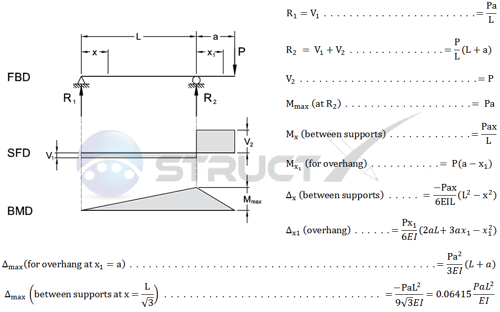
The formula for deflection of an overhang beam is a mathematical equation that calculates the amount of deflection that occurs in a beam that is supported at one end and has a load applied at the other end. The formula is based on the beam's length, load, and moment of inertia, and is used to determine the maximum deflection that will occur in the beam. The formula for deflection of an overhang beam is: Δ = (W L^3) / (3 E I), where Δ is the deflection, W is the load, L is the length of the beam, E is the modulus of elasticity, and I is the moment of inertia.
Understanding the Formula for Deflection of an Overhang Beam
The formula for deflection of an overhang beam is based on the principles of mechanics of materials and is used to calculate the amount of deflection that occurs in a beam under a given load. To understand the formula, it is necessary to have a good understanding of the variables involved, including the load, length, modulus of elasticity, and moment of inertia. Some key points to consider when using the formula include:
- The load must be applied at the end of the beam, and the beam must be supported at the other end.
- The length of the beam must be known, as well as the modulus of elasticity and moment of inertia of the beam material.
- The formula assumes a simply supported beam, meaning that the beam is supported at the ends and is free to rotate at the supports.
Calculating the Moment of Inertia for an Overhang Beam
The moment of inertia is an important variable in the formula for deflection of an overhang beam, and is used to calculate the resistance of the beam to bending. The moment of inertia can be calculated using the formula: I = (b h^3) / 12, where b is the width of the beam and h is the height of the beam. Some key points to consider when calculating the moment of inertia include:
- The width and height of the beam must be known, as well as the cross-sectional area of the beam.
- The formula assumes a rectangular cross-section, meaning that the beam has a constant width and height.
- The moment of inertia is calculated about the neutral axis of the beam, which is the axis that passes through the centroid of the cross-section.
Applying the Formula for Deflection of an Overhang Beam
The formula for deflection of an overhang beam can be applied to a variety of real-world engineering problems, including the design of bridges, buildings, and machinery. To apply the formula, it is necessary to have a good understanding of the loads and supports involved, as well as the material properties of the beam. Some key points to consider when applying the formula include:
- The load must be applied at the end of the beam, and the beam must be supported at the other end.
- The length of the beam must be known, as well as the modulus of elasticity and moment of inertia of the beam material.
- The formula assumes a static load, meaning that the load is applied slowly and does not change over time.
Assumptions and Limitations of the Formula for Deflection of an Overhang Beam
The formula for deflection of an overhang beam is based on several assumptions and limitations, including the assumption of a simply supported beam and the assumption of a static load. Some key points to consider when using the formula include:
- The formula assumes a linear elastic material, meaning that the material will return to its original shape after the load is removed.
- The formula assumes a small deflection, meaning that the deflection is much smaller than the length of the beam.
- The formula does not account for dynamic loads, meaning that the load changes over time.
Real-World Applications of the Formula for Deflection of an Overhang Beam
The formula for deflection of an overhang beam has a variety of real-world applications, including the design of bridges, buildings, and machinery. Some key points to consider when applying the formula to real-world problems include:
- The load must be applied at the end of the beam, and the beam must be supported at the other end.
- The length of the beam must be known, as well as the modulus of elasticity and moment of inertia of the beam material.
- The formula can be used to calculate the maximum deflection that will occur in the beam, as well as the stress and strain that will occur in the beam material.
What is the formula for the deflection of a beam fixed at both ends?
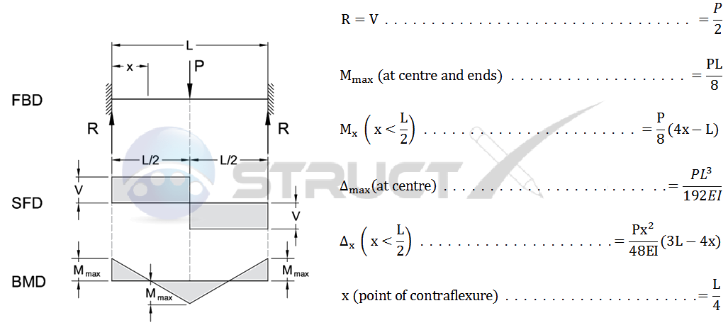
The formula for the deflection of a beam fixed at both ends is given by the equation δ = (W L^3) / (192 E I), where δ is the deflection, W is the load, L is the length of the beam, E is the modulus of elasticity, and I is the moment of inertia. This equation is used to calculate the maximum deflection of a beam that is fixed at both ends and subjected to a uniform load.
Assumptions and Limitations
The formula for the deflection of a beam fixed at both ends is based on several assumptions, including that the beam is homogeneous, isotropic, and linearly elastic. The formula also assumes that the load is uniformly distributed and that the beam is fixed at both ends, meaning that there is no rotation or displacement at the ends. Some key points to consider are:
- The formula is only applicable for beams with a rectangular or circular cross-section.
- The load must be static and uniformly distributed.
- The material must be linearly elastic, meaning that it follows Hooke's law.
Derivation of the Formula
The formula for the deflection of a beam fixed at both ends can be derived using the beam theory, which is based on the equilibrium equations and the constitutive equations. The derivation involves integrating the curvature of the beam to find the deflection, and then applying the boundary conditions to find the constants of integration. Some key steps in the derivation are:
- Define the curvature of the beam in terms of the deflection and the load.
- Integrate the curvature to find the deflection.
- Apply the boundary conditions to find the constants of integration.
Applications and Examples
The formula for the deflection of a beam fixed at both ends has many practical applications in engineering, including the design of buildings, bridges, and machinery. Some examples of how the formula can be used include:
- Designing a beam to support a given load while minimizing deflection.
- Analyzing the structural integrity of a building or bridge.
- Optimizing the shape and size of a beam to minimize weight while maintaining strength.
Comparison with Other Formulas
The formula for the deflection of a beam fixed at both ends is similar to other formulas for beam deflection, such as the formula for a simply supported beam or a cantilever beam. However, the formula for a fixed-end beam is more complex and requires more input parameters, including the length and moment of inertia of the beam. Some key differences between the formulas are:
- The boundary conditions for a fixed-end beam are different from those for a simply supported beam or a cantilever beam.
- The formula for a fixed-end beam involves more parameters, including the length and moment of inertia.
- The deflection of a fixed-end beam is generally less than that of a simply supported beam or a cantilever beam.
Numerical Methods and Approximations
In some cases, the formula for the deflection of a beam fixed at both ends may not be convenient or accurate to use, and numerical methods or approximations may be required. Some common numerical methods for solving beam problems include the finite element method and the boundary element method. Some key advantages and disadvantages of these methods are:
- The finite element method is versatile and can handle complex geometries and nonlinear materials.
- The boundary element method is efficient and can handle large problems with many degrees of freedom.
- Numerical methods can be computationally intensive and require specialized software.
What is the formula for bending a beam?

The formula for bending a beam is a complex equation that takes into account various factors such as the beam's material, length, and cross-sectional area. The most commonly used formula for bending a beam is the Euler-Bernoulli beam theory, which states that the deflection of a beam under a load is given by the equation: Δ = (P L^3) / (3 E I), where Δ is the deflection, P is the load, L is the length of the beam, E is the modulus of elasticity of the material, and I is the moment of inertia of the beam's cross-sectional area.
Types of Beam Supports
The type of support used for a beam can greatly affect its bending behavior. There are several types of supports, including simply supported, fixed, and cantilever. Each type of support has its own unique characteristics and affects the beam's deflection and stress distribution. Some key points to consider when designing a beam with different types of supports include:
- The simply supported beam is the most common type of support, where the beam is supported at both ends and allowed to rotate freely.
- The fixed support is used when the beam is fixed at one end and not allowed to rotate, which can increase the stiffness of the beam.
- The cantilever support is used when the beam is fixed at one end and free at the other, which can create a moment at the fixed end.
Materials Used for Beams
The material used for a beam can greatly affect its bending behavior. Different materials have different modulus of elasticity and yield strength values, which can affect the beam's deflection and stress distribution. Some common materials used for beams include:
- Steel, which has a high modulus of elasticity and yield strength, making it a popular choice for beams.
- Aluminum, which has a lower modulus of elasticity and yield strength than steel, but is often used for beams due to its lightweight and corrosion-resistant properties.
- Wood, which has a lower modulus of elasticity and yield strength than steel or aluminum, but is often used for beams due to its sustainability and aesthetics.
Beam Cross-Sectional Shapes
The cross-sectional shape of a beam can greatly affect its bending behavior. Different shapes have different moment of inertia values, which can affect the beam's deflection and stress distribution. Some common cross-sectional shapes used for beams include:
- Rectangular, which has a simple and symmetric shape, making it easy to analyze and design.
- Circular, which has a continuous and smooth shape, making it resistant to bending and torsion.
- I-shaped, which has a complex shape with a web and flanges, making it efficient for bending and tension.
Load Types and Applications
The type of load applied to a beam can greatly affect its bending behavior. Different loads have different magnitude and distribution values, which can affect the beam's deflection and stress distribution. Some common load types and applications include:
- Uniformly distributed load, which is often used to model dead loads such as the weight of a roof or floor.
- Concentrated load, which is often used to model live loads such as the weight of a person or vehicle.
- Dynamic load, which is often used to model vibrations or impact loads, such as those caused by wind or earthquakes.
Design Considerations and Safety Factors
When designing a beam, it is essential to consider various design considerations and safety factors to ensure the beam can withstand the applied loads and stresses. Some key points to consider include:
- The factor of safety, which is used to account for uncertainties and variabilities in the design and loading conditions.
- The material properties, such as the modulus of elasticity and yield strength, which can affect the beam's deflection and stress distribution.
- The beam's support conditions, which can affect the beam's deflection and stress distribution, and must be carefully considered to ensure the beam's stability and safety.
How do you calculate the stress of a beam?

To calculate the stress of a beam, you need to understand the forces and moments acting on it. The stress calculation involves determining the bending moment, shear force, and torque at a given point on the beam. This is typically done using the beam theory, which assumes that the beam is a straight and prismatic member. The stress is then calculated using the flexural formula, which takes into account the moment of inertia of the beam's cross-section.
Understanding Beam Geometry
To calculate the stress of a beam, it's essential to understand the beam geometry, including the length, width, and height of the beam. The cross-sectional area and moment of inertia are also critical in determining the stress. Here are the key factors to consider:
- The beam length and support conditions affect the bending moment and shear force diagrams.
- The cross-sectional area and moment of inertia influence the flexural rigidity of the beam.
- The beam material and its properties, such as the elastic modulus and Poisson's ratio, are necessary for stress calculations.
Calculating Bending Moment and Shear Force
The bending moment and shear force diagrams are crucial in determining the stress at a given point on the beam. These diagrams can be calculated using the beam theory and the load and support conditions. The bending moment is calculated by integrating the shear force diagram, while the shear force is calculated by differentiating the bending moment diagram. Here are the key steps:
- Determine the load and support conditions of the beam.
- Calculate the bending moment and shear force diagrams using the beam theory.
- Use the flexural formula to calculate the stress at a given point on the beam.
Determining Moment of Inertia
The moment of inertia is a critical factor in calculating the stress of a beam. It depends on the cross-sectional shape and dimensions of the beam. The moment of inertia can be calculated using the parallel axis theorem or the perimeter method. Here are the key considerations:
- The cross-sectional shape and dimensions affect the moment of inertia.
- The moment of inertia is used in the flexural formula to calculate the stress.
- The parallel axis theorem and perimeter method can be used to calculate the moment of inertia.
Applying Flexural Formula
The flexural formula is used to calculate the stress at a given point on the beam. It takes into account the bending moment, moment of inertia, and distance from the neutral axis. The flexural formula is given by σ = M y / I, where σ is the stress, M is the bending moment, y is the distance from the neutral axis, and I is the moment of inertia. Here are the key factors:
- The flexural formula is used to calculate the stress at a given point on the beam.
- The bending moment and moment of inertia are necessary for the flexural formula.
- The distance from the neutral axis affects the stress calculation.
Considering Material Properties
The material properties, such as the elastic modulus and Poisson's ratio, are essential in calculating the stress of a beam. The elastic modulus affects the flexural rigidity of the beam, while the Poisson's ratio affects the lateral strain. Here are the key considerations:
- The elastic modulus affects the flexural rigidity of the beam.
- The Poisson's ratio affects the lateral strain and stress calculation.
- The material properties are necessary for stress calculations and design of the beam.
Frequently Asked Questions (FAQs)
What is the purpose of the Beam Deflection and Stress Equations Calculator for Beam with Ends Overhanging Supports and a Two Equal Loads applied at Symmetrical Locations?
The Beam Deflection and Stress Equations Calculator is a mathematical tool designed to calculate the deflection and stress of a beam with overhanging ends and two equal loads applied at symmetrical locations. This calculator is used to determine the maximum deflection and maximum stress that occurs in the beam due to the applied loads. The calculator takes into account the length of the beam, the distance between the supports, the magnitude of the loads, and the material properties of the beam. By using this calculator, engineers and designers can quickly and easily determine the structural integrity of the beam and ensure that it can withstand the applied loads without failure. The calculator is also useful for optimizing the design of the beam to minimize deflection and stress while maximizing strength and stiffness.
How does the Beam Deflection and Stress Equations Calculator for Beam with Ends Overhanging Supports and a Two Equal Loads applied at Symmetrical Locations work?
The Beam Deflection and Stress Equations Calculator uses a set of complex equations to calculate the deflection and stress of the beam. The calculator first calculates the reaction forces at the supports using the equilibrium equations, and then uses these forces to calculate the bending moment and shear force diagrams for the beam. The calculator then uses these diagrams to calculate the maximum deflection and maximum stress that occurs in the beam. The calculator also takes into account the boundary conditions of the beam, such as the fixed or simply supported ends, and the symmetrical loading condition. The calculator uses a numerical method to solve the differential equations that govern the behavior of the beam, and provides a accurate and reliable solution for the deflection and stress of the beam.
What are the advantages of using the Beam Deflection and Stress Equations Calculator for Beam with Ends Overhanging Supports and a Two Equal Loads applied at Symmetrical Locations?
The Beam Deflection and Stress Equations Calculator has several advantages that make it a useful tool for engineers and designers. One of the main advantages is that it provides a quick and easy way to calculate the deflection and stress of a beam, without the need for complex and time-consuming calculations. The calculator is also accurate and reliable, providing a trustworthy solution for the deflection and stress of the beam. Another advantage is that the calculator allows for parametric studies to be performed, where the effects of different design parameters on the deflection and stress of the beam can be investigated. This allows engineers and designers to optimize the design of the beam to meet specific requirements. Additionally, the calculator is user-friendly and intuitive, making it easy to use even for those without extensive experience in structural analysis.
What are the limitations of the Beam Deflection and Stress Equations Calculator for Beam with Ends Overhanging Supports and a Two Equal Loads applied at Symmetrical Locations?
The Beam Deflection and Stress Equations Calculator has several limitations that should be considered when using it. One of the main limitations is that it assumes a linear elastic behavior of the beam, which may not be accurate for beams made of non-linear materials. The calculator also assumes a symmetrical loading condition, which may not be representative of all loading conditions. Additionally, the calculator does not take into account dynamic loads or impact loads, which can be important for certain applications. The calculator also assumes a simple support condition, which may not be representative of all support conditions. Furthermore, the calculator does not provide a detailed analysis of the stress and strain distribution in the beam, which may be necessary for certain applications. Therefore, the calculator should be used with caution and judgment, and the results should be verified using other methods or tools when possible.
Deja una respuesta
Entradas Relacionadas