
Cantilever Beam with Mass at End Natural Frequency Calculator

The Cantilever Beam with Mass at End Natural Frequency Calculator is a tool used to determine the natural frequency of a cantilever beam with a mass attached to its free end. This calculation is crucial in various engineering applications, including mechanical, civil, and aerospace engineering. The natural frequency is a critical parameter in designing and analyzing systems to avoid resonance and ensure structural integrity. By using this calculator, users can quickly and accurately determine the natural frequency of a cantilever beam with a mass at its end, facilitating efficient design and analysis of systems.
- Cantilever Beam with Mass at End Natural Frequency Calculator: A Comprehensive Guide
- How to find the natural frequency of a cantilever beam?
- What is the natural frequency of mass on a beam?
- What is the period of the cantilever beam?
- What is the formula for a cantilever beam with point load at free end?
-
Frequently Asked Questions (FAQs)
- What is the Cantilever Beam with Mass at End Natural Frequency Calculator and how does it work?
- What are the key parameters that need to be input into the Cantilever Beam with Mass at End Natural Frequency Calculator?
- How is the natural frequency of a cantilever beam with mass at end calculated using the Cantilever Beam with Mass at End Natural Frequency Calculator?
- What are the limitations and assumptions of the Cantilever Beam with Mass at End Natural Frequency Calculator?
Cantilever Beam with Mass at End Natural Frequency Calculator: A Comprehensive Guide
A Cantilever Beam with Mass at End Natural Frequency Calculator is a tool used to calculate the natural frequency of a cantilever beam with a mass attached at its end. This calculator is essential in various engineering fields, including mechanical, civil, and aerospace engineering, where the dynamic behavior of beams is critical. The natural frequency of a beam is a fundamental parameter that determines its vibrational characteristics, and it is influenced by factors such as the beam's geometry, material properties, and the attached mass.
What is a Cantilever Beam?
A cantilever beam is a type of beam that is fixed at one end and free at the other. This type of beam is commonly used in various engineering applications, including bridges, buildings, and mechanical systems. The cantilever beam is subjected to various types of loads, including static and dynamic loads, which can cause it to vibrate. The natural frequency of the beam is a critical parameter that determines its vibrational behavior.
Importance of Natural Frequency Calculator
The natural frequency calculator is essential in designing and analyzing systems that involve cantilever beams. The calculator helps engineers to determine the natural frequency of the beam, which is critical in avoiding resonance and ensuring the structural integrity of the system. Resonance occurs when the frequency of the external force matches the natural frequency of the beam, leading to amplified vibrations and potentially catastrophic failures.
Key Parameters in Natural Frequency Calculation
The natural frequency of a cantilever beam with a mass at its end depends on several key parameters, including:
| Parameter | Description |
|---|---|
| Beam length | The length of the cantilever beam |
| Beam width | The width of the cantilever beam |
| Beam thickness | The thickness of the cantilever beam |
| Mass at end | The mass attached at the end of the cantilever beam |
| Material properties | The mechanical properties of the beam material, such as Young's modulus and density |
Calculation Methodology
The natural frequency of a cantilever beam with a mass at its end can be calculated using various methodologies, including the finite element method and the analytical method. The finite element method involves discretizing the beam into smaller elements and solving the resulting equations to determine the natural frequency. The analytical method involves using mathematical models to derive the natural frequency of the beam.
Applications of Natural Frequency Calculator
The natural frequency calculator has various applications in engineering, including:
Vibration analysis: The calculator helps engineers to analyze the vibrational behavior of cantilever beams and avoid resonance.
Design optimization: The calculator enables engineers to optimize the design of cantilever beams by selecting the optimal beam geometry and material properties.
Structural health monitoring: The calculator helps engineers to monitor the structural health of cantilever beams and detect potential damage or failures.
How to find the natural frequency of a cantilever beam?
To find the natural frequency of a cantilever beam, we need to consider the physical properties of the beam, such as its length, width, thickness, and material density. The natural frequency is the frequency at which the beam vibrates when it is subjected to an external force and then released. The calculation of natural frequency involves the use of beam theory and vibration analysis.
Understanding Beam Theory
To find the natural frequency of a cantilever beam, we need to understand the basics of beam theory. This involves knowing the boundary conditions of the beam, such as the fixed end and the free end. The mode shapes of the beam are also important, as they describe the shape of the beam during vibration. The calculation of natural frequency can be done using the following steps:
- Determine the physical properties of the beam, such as its length, width, thickness, and material density.
- Calculate the moment of inertia of the beam, which is a measure of its resistance to bending.
- Use the beam equation to solve for the natural frequency, which is typically done using numerical methods or approximation techniques.
Calculating Natural Frequency
The calculation of natural frequency involves the use of mathematical equations and numerical methods. The natural frequency can be calculated using the following formula: ωn = (EI/ρAL^4)^(1/2), where ωn is the natural frequency, E is the modulus of elasticity, I is the moment of inertia, ρ is the material density, A is the cross-sectional area, and L is the length of the beam. The calculation can be done using:
- Finite element analysis, which involves dividing the beam into small elements and solving for the natural frequency using numerical methods.
- Analytical methods, which involve using mathematical equations to solve for the natural frequency.
- Experimental methods, which involve measuring the natural frequency of the beam using sensors and data acquisition systems.
Factors Affecting Natural Frequency
There are several factors that can affect the natural frequency of a cantilever beam, including -material properties, geometric properties, and boundary conditions. The natural frequency can be affected by:
- Material properties, such as the modulus of elasticity and material density.
- Geometric properties, such as the length, width, and thickness of the beam.
- Boundary conditions, such as the fixed end and free end of the beam.
Applications of Natural Frequency
The natural frequency of a cantilever beam has several practical applications, including vibration analysis, structural design, and condition monitoring. The natural frequency can be used to:
- Predict vibration behavior, which is important for machine design and structural integrity.
- Design structures, such as buildings and bridges, to withstand wind and earthquake loads.
- Monitor condition, which is important for predictive maintenance and fault detection.
Measurement Techniques
There are several measurement techniques that can be used to measure the natural frequency of a cantilever beam, including accelerometers, strain gauges, and laser vibrometry. The measurement can be done using:
- Contact methods, which involve attaching sensors to the beam to measure its vibration.
- Non-contact methods, which involve using laser or optical techniques to measure the vibration of the beam.
- Signal processing techniques, which involve using algorithms and software to analyze the measured data and extract the natural frequency.
What is the natural frequency of mass on a beam?

The natural frequency of a mass on a beam is a fundamental concept in mechanical engineering and vibrations. It refers to the frequency at which the mass tends to oscillate or vibrate when subjected to an external force or disturbance. The natural frequency is determined by the stiffness of the beam, the mass of the object, and the frequency of the external force. To calculate the natural frequency, we need to consider the equation of motion of the mass on the beam, which is typically represented by a second-order differential equation.
Natural Frequency Calculation
The natural frequency calculation involves determining the resonant frequency of the system, which is the frequency at which the mass oscillates with maximum amplitude. This can be calculated using the formula: ωn = √(k/m), where ωn is the natural frequency, k is the stiffness of the beam, and m is the mass of the object. The calculation also involves considering the boundary conditions of the beam, such as the support conditions and the loading conditions. Some key points to consider are:
- Mass: The mass of the object affects the natural frequency, with larger masses resulting in lower natural frequencies.
- Stiffness: The stiffness of the beam also affects the natural frequency, with stiffer beams resulting in higher natural frequencies.
- Frequency: The frequency of the external force can also affect the natural frequency, with resonant frequencies resulting in maximum oscillation amplitudes.
Types of Beam Supports
The type of beam support can also affect the natural frequency of the mass on the beam. Different types of supports, such as simply supported, clamped, or free supports, can result in different boundary conditions and natural frequencies. For example, a simply supported beam has a lower natural frequency than a clamped beam. Some key points to consider are:
- Simply supported: This type of support results in a lower natural frequency due to the flexibility of the beam.
- Clamped: This type of support results in a higher natural frequency due to the stiffness of the beam.
- Free: This type of support results in a higher natural frequency due to the lack of constraints on the beam.
Effects of Damping
Damping can also affect the natural frequency of the mass on the beam. Damping refers to the energy loss that occurs as the mass oscillates, typically due to friction or viscous forces. The damping ratio can be used to calculate the damped natural frequency, which is typically lower than the undamped natural frequency. Some key points to consider are:
- Damping ratio: The damping ratio affects the damped natural frequency, with higher damping ratios resulting in lower natural frequencies.
- Energy loss: The energy loss due to damping affects the natural frequency, with higher energy losses resulting in lower natural frequencies.
- Viscous forces: The viscous forces that cause damping can affect the natural frequency, with higher viscous forces resulting in lower natural frequencies.
Vibration Modes
The vibration modes of the mass on the beam can also affect the natural frequency. The vibration modes refer to the patterns of motion that the mass exhibits as it oscillates, typically represented by mode shapes. The mode shapes can be used to calculate the natural frequencies of the system, with different modes resulting in different natural frequencies. Some key points to consider are:
- Mode shapes: The mode shapes affect the natural frequencies, with different modes resulting in different natural frequencies.
- Vibration patterns: The vibration patterns affect the natural frequencies, with different patterns resulting in different natural frequencies.
- Frequency spectrum: The frequency spectrum of the system can be used to calculate the natural frequencies, with different frequencies resulting in different modes.
Experimental Measurement
The natural frequency of the mass on the beam can be measured experimentally using various techniques, such as impact testing or shaker testing. These techniques involve applying an external force to the mass and measuring the resulting vibration response. The vibration response can be used to calculate the natural frequency of the system, typically using fast Fourier transform (FFT) analysis. Some key points to consider are:
- Impact testing: This technique involves applying a sudden impact to the mass and measuring the resulting vibration response.
- Shaker testing: This technique involves applying a periodic force to the mass and measuring the resulting vibration response.
- FFT analysis: This technique involves analyzing the vibration response using FFT to calculate the natural frequency of the system.
What is the period of the cantilever beam?
The period of a cantilever beam is a critical parameter in understanding its dynamic behavior. It refers to the time taken by the beam to complete one cycle of vibration. The period of a cantilever beam depends on several factors, including its length, cross-sectional area, and material properties.
Introduction to Cantilever Beam Dynamics
The dynamics of a cantilever beam are complex and involve the interaction of various forces and moments. To determine the period of a cantilever beam, one needs to consider the equations of motion that govern its behavior. The period can be calculated using the following formula: T = 2π √(m/k), where T is the period, m is the mass of the beam, and k is the stiffness of the beam.
- The mass of the beam is a critical parameter in determining its period, as it affects the inertia of the beam.
- The stiffness of the beam is also important, as it determines the resistance of the beam to deformation.
- The damping characteristics of the beam can also affect its period, as they determine the energy loss during each cycle of vibration.
Factors Affecting the Period of a Cantilever Beam
Several factors can affect the period of a cantilever beam, including its geometric and material properties. The length and cross-sectional area of the beam can significantly impact its period, as they affect the mass and stiffness of the beam. Additionally, the boundary conditions of the beam, such as the support conditions, can also influence its period.
- The length of the beam is a critical parameter, as it affects the mass and stiffness of the beam.
- The cross-sectional area of the beam is also important, as it determines the moment of inertia of the beam.
- The material properties, such as the Young's modulus and Poisson's ratio, can also affect the period of the beam.
Calculation of the Period of a Cantilever Beam
The calculation of the period of a cantilever beam involves the use of mathematical models and numerical methods. The equations of motion that govern the behavior of the beam can be solved using techniques such as the finite element method or the Rayleigh-Ritz method. The period can be calculated using the following formula: T = 2π √(m/k), where T is the period, m is the mass of the beam, and k is the stiffness of the beam.
- The finite element method is a popular technique for calculating the period of a cantilever beam, as it allows for the discretization of the beam into smaller elements.
- The Rayleigh-Ritz method is another technique that can be used to calculate the period of a cantilever beam, as it allows for the approximation of the mode shapes of the beam.
- The numerical integration of the equations of motion can also be used to calculate the period of the beam, as it allows for the solution of the differential equations that govern the behavior of the beam.
Applications of Cantilever Beams
Cantilever beams have a wide range of applications in various fields, including civil engineering, mechanical engineering, and aerospace engineering. They are commonly used in structures such as bridges, buildings, and aircraft, where they provide support and stability.
- Cantilever beams are used in bridges to provide support for the deck and to resist the forces caused by traffic and wind.
- Cantilever beams are used in buildings to provide support for the floors and roofs, and to resist the forces caused by gravity and wind.
- Cantilever beams are used in aircraft to provide support for the wings and tail, and to resist the forces caused by aerodynamic and inertial loads.
Experimental Methods for Measuring the Period of a Cantilever Beam
The period of a cantilever beam can be measured using experimental methods, such as vibration testing and modal analysis. These methods involve the use of sensors and data acquisition systems to measure the vibration of the beam and to determine its mode shapes and frequencies.
- The vibration testing method involves the use of accelerometers and data acquisition systems to measure the vibration of the beam.
- The modal analysis method involves the use of sensors and data acquisition systems to measure the mode shapes and frequencies of the beam.
- The experimental results can be used to validate the mathematical models and to improve the accuracy of the calculations.
What is the formula for a cantilever beam with point load at free end?
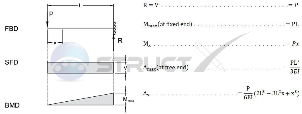
The formula for a cantilever beam with a point load at the free end is given by the equation for the deflection and stress at any point along the beam. The deflection (y) at any point x along the beam is given by the equation: y = (P x^2) / (2 E I), where P is the point load, x is the distance from the fixed end, E is the modulus of elasticity, and I is the moment of inertia of the beam. The stress (σ) at any point x along the beam is given by the equation: σ = (P x) / I, where P is the point load, x is the distance from the fixed end, and I is the moment of inertia of the beam.
Derivation of the Formula
The derivation of the formula for a cantilever beam with a point load at the free end involves the use of the beam theory and the equilibrium equations. The beam theory states that the deflection (y) of a beam is given by the equation: y = (P x^2) / (2 E I), where P is the point load, x is the distance from the fixed end, E is the modulus of elasticity, and I is the moment of inertia of the beam. The equilibrium equations are used to derive the stress (σ) at any point x along the beam, which is given by the equation: σ = (P x) / I, where P is the point load, x is the distance from the fixed end, and I is the moment of inertia of the beam. Some key points to consider when deriving the formula are:
- The beam theory assumes that the beam is straight and prismatic.
- The equilibrium equations are used to derive the stress (σ) at any point x along the beam.
- The moment of inertia (I) of the beam is an important parameter in the formula.
Assumptions of the Formula
The formula for a cantilever beam with a point load at the free end is based on several assumptions, including the beam theory and the equilibrium equations. The beam theory assumes that the beam is straight and prismatic, and that the deflection (y) is small compared to the length of the beam. The equilibrium equations assume that the beam is in equilibrium and that the forces and moments acting on the beam are balanced. Some key assumptions to consider are:
- The beam is straight and prismatic.
- The deflection (y) is small compared to the length of the beam.
- The beam is in equilibrium and the forces and moments acting on the beam are balanced.
Applications of the Formula
The formula for a cantilever beam with a point load at the free end has several applications in engineering and design. The formula is used to calculate the deflection (y) and stress (σ) of a cantilever beam under a point load, which is important in the design of structures such as bridges, buildings, and machinery. Some key applications to consider are:
- Design of structures such as bridges, buildings, and machinery.
- Calculation of the deflection (y) and stress (σ) of a cantilever beam under a point load.
- Analysis of the behavior of a cantilever beam under different loading conditions.
Limitations of the Formula
The formula for a cantilever beam with a point load at the free end has several limitations, including the assumptions of the beam theory and the equilibrium equations. The beam theory assumes that the beam is straight and prismatic, and that the deflection (y) is small compared to the length of the beam. The equilibrium equations assume that the beam is in equilibrium and that the forces and moments acting on the beam are balanced. Some key limitations to consider are:
- The beam theory assumes that the beam is straight and prismatic.
- The equilibrium equations assume that the beam is in equilibrium and that the forces and moments acting on the beam are balanced.
- The formula does not account for nonlinear behavior or dynamic loading.
Comparison with Other Formulas
The formula for a cantilever beam with a point load at the free end can be compared with other formulas for beams under different loading conditions. For example, the formula for a simply supported beam with a uniformly distributed load is given by the equation: y = (w x (L - x)) / (2 E I), where w is the uniformly distributed load, x is the distance from one end of the beam, L is the length of the beam, E is the modulus of elasticity, and I is the moment of inertia of the beam. Some key comparisons to consider are:
- The formula for a simply supported beam with a uniformly distributed load is different from the formula for a cantilever beam with a point load at the free end.
- The deflection (y) and stress (σ) of a beam under different loading conditions can be calculated using different formulas.
- The choice of formula depends on the specific loading condition and the type of beam being analyzed.
Frequently Asked Questions (FAQs)
What is the Cantilever Beam with Mass at End Natural Frequency Calculator and how does it work?
The Cantilever Beam with Mass at End Natural Frequency Calculator is a mathematical tool designed to calculate the natural frequency of a cantilever beam with a mass attached to its end. This calculator uses the dimensions of the beam, such as its length, width, and thickness, as well as the mass and material properties, to determine the natural frequency of the system. The natural frequency is an important parameter in vibration analysis, as it determines the frequency at which the system will oscillate when subjected to an external force. The calculator uses complex mathematical formulas to take into account the effects of the mass on the beam's stiffness and damping, allowing for an accurate calculation of the natural frequency.
What are the key parameters that need to be input into the Cantilever Beam with Mass at End Natural Frequency Calculator?
To use the Cantilever Beam with Mass at End Natural Frequency Calculator, several key parameters need to be input, including the length, width, and thickness of the beam, as well as the mass attached to its end. Additionally, the material properties of the beam, such as its density and Young's modulus, must also be input. These parameters are used to calculate the beam's stiffness and damping, which are critical factors in determining the natural frequency of the system. The accuracy of the calculation depends on the accuracy of the input parameters, so it is essential to ensure that the input values are correct and precise. The calculator also allows for the input of optional parameters, such as the beam's cross-sectional area and moment of inertia, which can be used to refine the calculation and provide a more accurate result.
How is the natural frequency of a cantilever beam with mass at end calculated using the Cantilever Beam with Mass at End Natural Frequency Calculator?
The natural frequency of a cantilever beam with mass at end is calculated using the Cantilever Beam with Mass at End Natural Frequency Calculator by first calculating the beam's stiffness and damping using the input parameters. The calculator then uses these values to calculate the natural frequency of the system using complex mathematical formulas, such as the Rayleigh-Ritz method or the finite element method. These methods take into account the effects of the mass on the beam's stiffness and damping, allowing for an accurate calculation of the natural frequency. The calculator also uses numerical methods, such as numerical integration or numerical differentiation, to solve the equations of motion and determine the natural frequency. The result is a precise calculation of the natural frequency, which can be used to predict the vibration behavior of the system.
What are the limitations and assumptions of the Cantilever Beam with Mass at End Natural Frequency Calculator?
The Cantilever Beam with Mass at End Natural Frequency Calculator has several limitations and assumptions that must be considered when using the tool. One of the main limitations is that the calculator assumes a simple cantilever beam with a mass attached to its end, and does not account for more complex systems, such as multi-degree-of-freedom systems or nonlinear systems. Additionally, the calculator assumes that the material properties of the beam are linear and isotropic, and does not account for nonlinear or anisotropic materials. The calculator also assumes that the damping is proportional to the stiffness, which may not be accurate for all systems. Furthermore, the calculator uses simplified mathematical models, which may not accurately capture the complex behavior of real-world systems. Therefore, the results of the calculator should be verified using experimental methods or more advanced numerical methods to ensure accuracy and reliability.
Deja una respuesta
Entradas Relacionadas