
Torsional Stiffness Hollow Shaft Equations and Calculator

The torsional stiffness of a hollow shaft is a critical parameter in mechanical engineering, particularly in the design of drivetrain components, such as axles and drive shafts. It determines the shaft's ability to resist twisting under torque loads. Torsional stiffness is calculated using specific equations that take into account the shaft's geometry, material properties, and boundary conditions. This article provides an overview of the equations and formulas used to calculate the torsional stiffness of a hollow shaft, along with a calculator to simplify the process and ensure accurate results for engineers and designers.
- Torsional Stiffness of Hollow Shafts: Understanding the Equations and Calculator
- How do you calculate torsional stiffness of a shaft?
- What is the formula for torsion on a shaft?
- How do you calculate torsional stress?
- What is the J formula for shaft?
-
Frequently Asked Questions (FAQs)
- What is Torsional Stiffness and its Importance in Hollow Shafts?
- How to Calculate Torsional Stiffness of a Hollow Shaft using Equations?
- What are the Key Factors that Affect the Torsional Stiffness of a Hollow Shaft?
- How can a Calculator be Used to Determine the Torsional Stiffness of a Hollow Shaft?
Torsional Stiffness of Hollow Shafts: Understanding the Equations and Calculator
The torsional stiffness of a hollow shaft is a critical parameter in mechanical engineering, particularly in the design of rotating machinery and power transmission systems. It is a measure of the shaft's resistance to torsional deformation when subjected to an external torque. The calculation of torsional stiffness involves the use of complex equations that take into account the shaft's geometry, material properties, and boundary conditions.
Introduction to Torsional Stiffness
Torsional stiffness is defined as the ratio of the applied torque to the resulting angle of twist. It is a measure of the shaft's ability to resist torsional loads and maintain its shape. The torsional stiffness equation can be derived from the theory of elasticity and is given by the formula: K = (G J) / L, where K is the torsional stiffness, G is the shear modulus, J is the polar moment of inertia, and L is the length of the shaft.
Hollow Shaft Equations
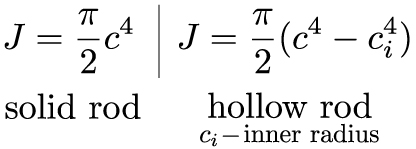
The equations for the torsional stiffness of a hollow shaft are more complex than those for a solid shaft. The polar moment of inertia (J) of a hollow shaft can be calculated using the formula: J = (π (R_o^4 - R_i^4)) / 2, where R_o is the outer radius and R_i is the inner radius of the shaft. The torsional stiffness equation for a hollow shaft is given by: K = (G (π (R_o^4 - R_i^4)) / 2) / L.
Calculator for Torsional Stiffness
A torsional stiffness calculator can be used to simplify the calculation process. The calculator takes into account the shaft's geometry, material properties, and boundary conditions to calculate the torsional stiffness. The input parameters include the outer and inner radii, length, and material properties such as the shear modulus. The calculator then uses the equations to calculate the polar moment of inertia and torsional stiffness.
Material Properties and Torsional Stiffness
The material properties of the shaft have a significant impact on its torsional stiffness. The shear modulus (G) is a critical parameter in the calculation of torsional stiffness. The shear modulus is a measure of the material's resistance to shear stress. The density of the material also affects the torsional stiffness, as it affects the polar moment of inertia.
Applications of Torsional Stiffness
The torsional stiffness of a hollow shaft has numerous applications in mechanical engineering. It is used in the design of power transmission systems, rotating machinery, and aerospace engineering. The torsional stiffness is also critical in the design of shafts and axles in automotive engineering. The following table summarizes the key parameters and equations used in the calculation of torsional stiffness:
| Parameter | Equation | Description |
|---|---|---|
| Torsional Stiffness | K = (G J) / L | Measure of the shaft's resistance to torsional deformation |
| Polar Moment of Inertia | J = (π (R_o^4 - R_i^4)) / 2 | Measure of the shaft's resistance to torsional loads |
| Shear Modulus | G | Measure of the material's resistance to shear stress |
How do you calculate torsional stiffness of a shaft?
To calculate the torsional stiffness of a shaft, you need to understand the relationship between the applied torque and the resulting angular displacement. The torsional stiffness of a shaft is a measure of its resistance to twisting and is typically denoted by the symbol k. It is calculated using the formula k = T/θ, where T is the applied torque and θ is the resulting angular displacement. The shaft material, diameter, and length all play a significant role in determining the torsional stiffness of a shaft.
Understanding Torsional Stiffness
The torsional stiffness of a shaft is a critical parameter in the design of rotating machinery, such as engines and transmissions. To calculate the torsional stiffness of a shaft, you need to consider the material properties, including the modulus of rigidity and the Poisson's ratio. The calculation involves the following steps:
- Determine the shaft geometry, including the diameter and length.
- Calculate the polar moment of inertia, which is a measure of the shaft's resistance to torsion.
- Apply the formula k = (G J) / L, where G is the modulus of rigidity, J is the polar moment of inertia, and L is the length of the shaft.
Factors Affecting Torsional Stiffness
Several factors can affect the torsional stiffness of a shaft, including the material properties, shaft geometry, and surface finish. The modulus of rigidity of the shaft material is a key factor, as it determines the shaft's resistance to torsion. Other factors, such as the diameter and length of the shaft, also play a significant role in determining the torsional stiffness. The calculation involves the following considerations:
- The shaft diameter affects the polar moment of inertia, which in turn affects the torsional stiffness.
- The shaft length affects the torsional stiffness, as longer shafts tend to be less stiff than shorter shafts.
- The surface finish of the shaft can affect the friction and wear characteristics, which can in turn affect the torsional stiffness.
Torsional Stiffness Calculation Methods
There are several methods for calculating the torsional stiffness of a shaft, including the analytical method, finite element method, and experimental method. The analytical method involves using mathematical equations to calculate the torsional stiffness, while the finite element method involves using numerical simulations to model the shaft's behavior. The experimental method involves measuring the torsional stiffness directly using test equipment. The calculation involves the following steps:
- Choose a suitable calculation method based on the shaft geometry and material properties.
- Apply the mathematical equations or numerical simulations to calculate the torsional stiffness.
- Validate the results using experimental data or other calculation methods.
Applications of Torsional Stiffness
The torsional stiffness of a shaft has significant implications for the design and operation of rotating machinery, such as engines and transmissions. A higher torsional stiffness can result in improved performance and reduced vibrations, while a lower torsional stiffness can result in reduced durability and increased wear. The calculation involves the following considerations:
- The torsional stiffness affects the natural frequency of the shaft, which can impact the vibration characteristics.
- The torsional stiffness affects the stress and strain characteristics of the shaft, which can impact the fatigue life.
- The torsional stiffness affects the dynamic behavior of the shaft, which can impact the overall performance of the machine.
Limitations and Challenges
There are several limitations and challenges associated with calculating the torsional stiffness of a shaft, including the complexity of the shaft geometry, non-uniform material properties, and experimental uncertainties. The calculation involves the following considerations:
- The shaft geometry can be complex, with variations in diameter and length.
- The material properties can be non-uniform, with variations in modulus of rigidity and Poisson's ratio.
- The experimental uncertainties can affect the accuracy of the measurement, particularly for small shaft diameters or high-speed applications.
What is the formula for torsion on a shaft?
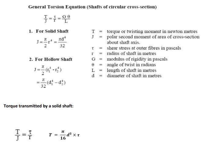
The formula for torsion on a shaft is given by the equation: T = (G J) / L θ, where T is the torsion moment, G is the shear modulus of the material, J is the polar moment of inertia of the shaft, L is the length of the shaft, and θ is the angle of twist.
Torsion Formula Components
The formula for torsion on a shaft involves several key components, including the shear modulus (G), polar moment of inertia (J), length (L), and angle of twist (θ). These components are crucial in determining the torsion moment (T) that a shaft can withstand. The following are some key points to consider:
- The shear modulus (G) is a measure of a material's resistance to shear stress.
- The polar moment of inertia (J) is a measure of a shaft's resistance to torsion.
- The length (L) of the shaft affects the torsion moment, with longer shafts being more prone to torsion.
Torsion Calculation
Calculating torsion on a shaft involves using the formula T = (G J) / L θ. This requires knowledge of the shear modulus (G), polar moment of inertia (J), length (L), and angle of twist (θ) of the shaft. The following are some key steps to follow:
- Determine the shear modulus (G) of the material.
- Calculate the polar moment of inertia (J) of the shaft.
- Measure the length (L) of the shaft.
Torsion Applications
Torsion on a shaft has several important applications in engineering, including the design of power transmission systems, gearboxes, and axles. These applications require a thorough understanding of torsion and its effects on shafts. The following are some key considerations:
- Torsion can cause shafts to fail if not properly designed.
- Torsion can affect the efficiency of power transmission systems.
- Torsion can be used to measure the torque of a shaft.
Torsion Materials
The material used to make a shaft can have a significant impact on its torsion properties. Different materials have different shear moduli (G) and polar moments of inertia (J), which affect the torsion moment (T) that a shaft can withstand. The following are some key points to consider:
- Steel is a common material used for shafts due to its high shear modulus (G).
- Aluminum is a lightweight material that can be used for shafts, but it has a lower shear modulus (G) than steel.
- Titanium is a strong and lightweight material that is often used for shafts in aerospace applications.
Torsion Design
Designing a shaft to withstand torsion requires careful consideration of the torsion formula and its components. The following are some key considerations:
- Shaft diameter and length can affect the torsion moment (T).
- Material selection can impact the shear modulus (G) and polar moment of inertia (J) of the shaft.
- Shaft geometry can affect the polar moment of inertia (J) and torsion properties of the shaft.
How do you calculate torsional stress?
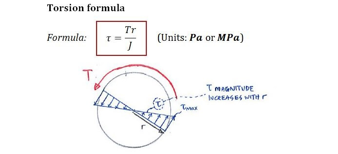
To calculate torsional stress, you need to understand the concept of torsion and its effects on an object. Torsion occurs when a force is applied to an object, causing it to twist or rotate around its longitudinal axis. The calculation of torsional stress involves determining the torque applied to the object, as well as its polar moment of inertia and shear modulus. The formula to calculate torsional stress is: τ = T r / J, where τ is the torsional stress, T is the torque, r is the radius of the object, and J is the polar moment of inertia.
Understanding Torsional Stress
Torsional stress is a type of shear stress that occurs when an object is subjected to a twisting force. It is essential to calculate torsional stress to determine the structural integrity of an object. The calculation involves understanding the material properties, such as the shear modulus, and the geometric properties, such as the polar moment of inertia. Some key points to consider when calculating torsional stress are:
- Torque: The force that causes the object to twist or rotate.
- Polar moment of inertia: A measure of the object's resistance to torsion.
- Shear modulus: A measure of the object's ability to withstand shear stress.
Factors Affecting Torsional Stress
Several factors can affect the calculation of torsional stress, including the shape and size of the object, the material properties, and the loading conditions. For example, a circular cross-section can withstand more torsional stress than a rectangular cross-section. Additionally, the length of the object can also affect the calculation, as longer objects are more susceptible to buckling. Some key factors to consider are:
- Cross-sectional shape: The shape of the object's cross-section can affect its resistance to torsion.
- Material properties: The shear modulus and other material properties can affect the object's ability to withstand torsional stress.
- Loading conditions: The type and magnitude of the loading conditions can affect the calculation of torsional stress.
Calculating Polar Moment of Inertia
The polar moment of inertia is a critical parameter in calculating torsional stress. It is a measure of the object's resistance to torsion and is calculated using the formula: J = ∫r^2 dA, where J is the polar moment of inertia, r is the radius of the object, and dA is the area element. The calculation involves integrating the area of the object's cross-section with respect to the radius. Some key points to consider are:
- Cross-sectional area: The area of the object's cross-section can affect the calculation of polar moment of inertia.
- Radius: The radius of the object can affect the calculation of polar moment of inertia.
- Integration: The integration of the area element with respect to the radius is necessary to calculate the polar moment of inertia.
Applications of Torsional Stress Calculation
The calculation of torsional stress has numerous practical applications in various fields, including mechanical engineering, civil engineering, and aerospace engineering. For example, in mechanical engineering, the calculation of torsional stress is essential in designing shafts, gears, and bearings. In civil engineering, the calculation of torsional stress is crucial in designing bridges and buildings. Some key applications are:
- Mechanical engineering: The calculation of torsional stress is essential in designing mechanical components.
- Civil engineering: The calculation of torsional stress is crucial in designing structures.
- Aerospace engineering: The calculation of torsional stress is necessary in designing aircraft and spacecraft components.
Common Mistakes in Torsional Stress Calculation
When calculating torsional stress, it is essential to avoid common mistakes, such as incorrect assumptions about the object's material properties or geometric properties. Additionally, numerical errors can occur if the calculation is not performed correctly. Some key mistakes to avoid are:
- Incorrect assumptions: Incorrect assumptions about the object's material properties or geometric properties can lead to errors in the calculation.
- Numerical errors: Numerical errors can occur if the calculation is not performed correctly.
- Unit conversions: Incorrect unit conversions can lead to errors in the calculation.
What is the J formula for shaft?
The J formula for shaft, also known as the Mohr's formula, is used to calculate the stress and strain on a shaft due to various types of loading. The formula is a combination of the bending stress, torsional stress, and axial stress that occur on a shaft. The formula is given by: J = (M r / I) + (T r / J), where J is the polar moment of inertia, M is the bending moment, r is the radius of the shaft, I is the moment of inertia, T is the torsional moment.
Understanding the J Formula Components
The J formula for shaft consists of various components that need to be understood in order to calculate the stress and strain on a shaft. These components include the bending moment, torsional moment, polar moment of inertia, and moment of inertia. The calculation involves the following steps:
- Calculating the bending stress using the formula M r / I
- Calculating the torsional stress using the formula T r / J
- Combining the bending and torsional stresses to get the total stress on the shaft
Applications of the J Formula
The J formula for shaft has various applications in the field of mechanical engineering, particularly in the design of shafts, gears, and bearings. The formula is used to calculate the stress and strain on a shaft due to various types of loading, including bending, torsion, and axial loading. The formula is also used to determine the safety factor of a shaft, which is essential in ensuring the reliability and performance of a mechanical system.
- Designing shafts for various mechanical systems, such as gearboxes and transmissions
- Calculating the stress and strain on gears and bearings
- Determining the safety factor of a shaft to ensure reliability and performance
Limitations of the J Formula
The J formula for shaft has some limitations that need to be considered when using it to calculate the stress and strain on a shaft. These limitations include the assumptions made in the formula, such as elastic behavior and symmetrical loading. The formula also does not account for dynamic loading and impact loads, which can significantly affect the stress and strain on a shaft.
- Assuming elastic behavior of the material, which may not always be true
- Assuming symmetrical loading, which may not always be the case
- Not accounting for dynamic loading and impact loads
Modifications to the J Formula
The J formula for shaft can be modified to account for various factors that are not considered in the original formula. These modifications include adjusting for dynamic loading, accounting for impact loads, and considering non-uniform cross-sections. The modified formula can provide more accurate results and can be used to design shafts and mechanical systems that are more reliable and efficient.
- Adjusting for dynamic loading using fatigue analysis
- Accounting for impact loads using impact analysis
- Considering non-uniform cross-sections using finite element analysis
Software for Calculating the J Formula
There are various software programs available that can be used to calculate the J formula for shaft, including finite element analysis software and mechanical design software. These programs can help engineers and designers to quickly and accurately calculate the stress and strain on a shaft and design mechanical systems that are more reliable and efficient.
- Using finite element analysis software to calculate the stress and strain on a shaft
- Using mechanical design software to design shafts and mechanical systems
- Verifying the results using experimental testing and validation
Frequently Asked Questions (FAQs)
What is Torsional Stiffness and its Importance in Hollow Shafts?
Torsional stiffness is a measure of a shaft's resistance to torsional deformation under an applied torque. It is an essential parameter in the design and analysis of hollow shafts, as it determines the shaft's ability to withstand twisting loads without excessive deformation or failure. The torsional stiffness of a hollow shaft is influenced by its geometric properties, such as the outer diameter, inner diameter, and length, as well as the material properties, like the modulus of rigidity or shear modulus. Understanding and accurately calculating the torsional stiffness of a hollow shaft is crucial for ensuring the structural integrity and performance of mechanical systems, particularly in applications where high-speed rotation or heavy loading is involved.
How to Calculate Torsional Stiffness of a Hollow Shaft using Equations?
Calculating the torsional stiffness of a hollow shaft involves using mathematical equations that take into account the shaft's geometric and material properties. One common equation used for this purpose is the torsional stiffness formula, which relates the torque applied to the shaft to the resulting angle of twist. The formula typically involves the modulus of rigidity, polar moment of inertia, and length of the shaft. By plugging in the known values and solving the equation, engineers can determine the torsional stiffness of the hollow shaft. However, it is essential to note that these calculations can be complex and require a thorough understanding of mechanics of materials and mathematical modeling. Additionally, calculator tools and software programs are often employed to simplify and streamline the calculation process, reducing the likelihood of human error and improving the accuracy of the results.
What are the Key Factors that Affect the Torsional Stiffness of a Hollow Shaft?
Several key factors can significantly impact the torsional stiffness of a hollow shaft, including its geometric dimensions, material properties, and operating conditions. The outer diameter and inner diameter of the shaft play a crucial role, as they affect the polar moment of inertia and, consequently, the torsional stiffness. The length of the shaft is also an essential factor, as it influences the angle of twist and the overall torsional stiffness. Furthermore, the material properties, such as the modulus of rigidity and yield strength, can significantly impact the shaft's resistance to torsional deformation. Other factors, like the temperature, surface finish, and end conditions, can also affect the torsional stiffness of the hollow shaft. By carefully considering these factors, engineers can optimize the design of the shaft to achieve the desired torsional stiffness and ensure reliable performance under various operating conditions.
How can a Calculator be Used to Determine the Torsional Stiffness of a Hollow Shaft?
A calculator can be a valuable tool for determining the torsional stiffness of a hollow shaft, as it allows for quick and accurate calculations. By inputting the known values, such as the geometric dimensions and material properties, into the calculator, engineers can easily obtain the torsional stiffness value. The calculator can also be used to iterate on different design scenarios, allowing engineers to explore the effects of various parameters on the of the shaft. Additionally, a calculator can help to validate the results of hand calculations or finite element analyses, providing an extra layer of confidence in the accuracy of the results. Many online calculators and software programs are available, offering a range of features and capabilities to support the calculation of torsional stiffness and other mechanical properties of hollow shafts. By leveraging these tools, engineers can streamline their design and analysis workflows, reducing the time and effort required to determine the torsional stiffness of a hollow shaft.
Deja una respuesta
Entradas Relacionadas