
Solid Square Section Torsional Deformation and Stress Torsional Deformation Stress Equation and Calculator

Torsional deformation occurs when a solid square section is subjected to twisting forces, causing it to rotate and deform. This deformation results in stresses that can lead to failure if not properly managed. The calculation of torsional deformation and stress is crucial in engineering design to ensure the stability and safety of structures. The torsional deformation stress equation provides a mathematical model to predict the behavior of solid square sections under torsion, allowing engineers to design and optimize structures for various applications. A calculator can be used to simplify the calculation process.
- Solid Square Section Torsional Deformation and Stress Torsional Deformation Stress Equation and Calculator
- What is the formula for torsional deformation and stress?
- How do you calculate torsional stress?
- How do you calculate the maximum shear stress of a shaft?
- How to calculate torsional resistance?
-
Frequently Asked Questions (FAQs)
- What is Solid Square Section Torsional Deformation and how is it calculated?
- How does the Torsional Deformation Stress Equation and Calculator work?
- What are the key factors that affect the Torsional Deformation and Stress of a Solid Square Section?
- How can the Torsional Deformation and Stress of a Solid Square Section be minimized or optimized?
Solid Square Section Torsional Deformation and Stress Torsional Deformation Stress Equation and Calculator
The solid square section is a type of structural element that is commonly used in engineering applications. When a torque is applied to this type of section, it can undergo torsional deformation, which can lead to stress and potentially cause failure. The torsional deformation stress equation is used to calculate the stress that occurs in the section due to the applied torque. A calculator can be used to simplify the calculation process.
Torsional Deformation and Stress Calculation
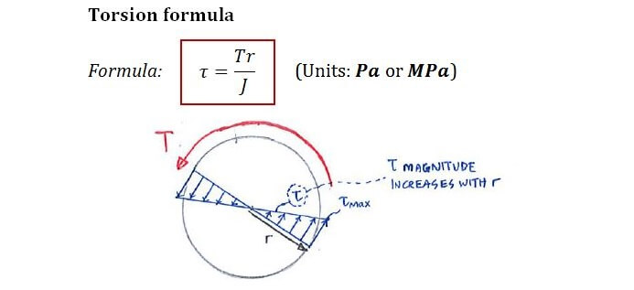
To calculate the torsional deformation stress, the polar moment of inertia of the section must be known. The polar moment of inertia is a measure of the section's resistance to torsion. The torsional deformation stress equation is given by: τ = T r / J, where τ is the shear stress, T is the torque, r is the distance from the centroid, and J is the polar moment of inertia. This equation can be used to calculate the stress that occurs in the section due to the applied torque.
Polar Moment of Inertia Calculation
The polar moment of inertia is calculated using the following equation: J = (1/12) b^4, where b is the side length of the square section. This equation is used to calculate the polar moment of inertia for a solid square section.
Torsional Deformation Stress Equation Derivation
The torsional deformation stress equation is derived from the equation of equilibrium for a solid square section. The equation of equilibrium is given by: ∑F = 0, where F is the force. By applying this equation to the solid square section, the torsional deformation stress equation can be derived.
Calculator for Torsional Deformation Stress
A calculator can be used to simplify the calculation process for the torsional deformation stress. The calculator can be programmed to calculate the stress using the torsional deformation stress equation. The user can input the torque, distance from the centroid, and polar moment of inertia, and the calculator will output the stress.
Applications of Torsional Deformation Stress Calculator
The torsional deformation stress calculator has many applications in engineering. It can be used to design shafts, beams, and other structural elements that are subject to torque. The calculator can also be used to analyze the stress that occurs in machine components such as gears and bearings.
| Parameter | Unit | Description |
|---|---|---|
| Torque | Nm | The torque applied to the section |
| Distance from centroid | m | The distance from the centroid of the section |
| Polar moment of inertia | m^4 | The polar moment of inertia of the section |
| Shear stress | Pa | The shear stress that occurs in the section |
What is the formula for torsional deformation and stress?
The formula for torsional deformation and stress is given by the equation: θ = (TL)/(GJ), where θ is the angle of twist, T is the applied torque, L is the length of the shaft, G is the shear modulus of the material, and J is the polar moment of inertia of the cross-sectional area. This formula is used to calculate the torsional deformation of a shaft under a given torque.
Torsional Deformation and Stress Formula
The formula for torsional deformation and stress is based on the twist angle, which is the angle by which the shaft twists under a given torque. The formula takes into account the length of the shaft, the shear modulus of the material, and the polar moment of inertia of the cross-sectional area. The formula can be used to calculate the torsional deformation of a shaft under a given torque, as well as the stress that is induced in the material. Some of the key factors that affect the torsional deformation and stress of a shaft include:
- The material properties, such as the shear modulus and the yield strength.
- The geometry of the shaft, including the length and the cross-sectional area.
- The Applied torque, which is the rotational force that is applied to the shaft.
Key Factors Affecting Torsional Deformation
The torsional deformation of a shaft is affected by several key factors, including the material properties, the geometry of the shaft, and the applied torque. The material properties, such as the shear modulus and the yield strength, play a crucial role in determining the torsional deformation of a shaft. The geometry of the shaft, including the length and the cross-sectional area, also affects the torsional deformation. Some of the key factors that affect the torsional deformation of a shaft include:
- The diameter of the shaft, which affects the polar moment of inertia.
- The wall thickness of the shaft, which affects the cross-sectional area.
- The material composition, which affects the shear modulus and the yield strength.
Calculating Torsional Stress
The torsional stress that is induced in a shaft under a given torque can be calculated using the formula: τ = (TR)/(J), where τ is the torsional stress, T is the applied torque, R is the radius of the shaft, and J is the polar moment of inertia of the cross-sectional area. This formula is used to calculate the torsional stress that is induced in the material, which is an important factor in determining the failure of the shaft. Some of the key factors that affect the torsional stress include:
- The applied torque, which is the rotational force that is applied to the shaft.
- The radius of the shaft, which affects the polar moment of inertia.
- The material properties, such as the shear modulus and the yield strength.
Torsional Deformation and Stress in Real-World Applications
The torsional deformation and stress of a shaft are critical factors in many real-world applications, including power transmission systems, gearboxes, and axles. In these applications, the torsional deformation and stress of the shaft can affect the performance and the reliability of the system. For example, in a power transmission system, the torsional deformation of the shaft can affect the efficiency of the system, while the torsional stress can affect the failure of the shaft. Some of the key considerations in real-world applications include:
- The operating conditions, such as the temperature and the environment.
- The maintenance and inspection requirements, which can affect the reliability of the system.
- The cost and the availability of replacement parts, which can affect the down time of the system.
Methods for Reducing Torsional Deformation and Stress
There are several methods that can be used to reduce the torsional deformation and stress of a shaft, including increasing the diameter of the shaft, increasing the wall thickness of the shaft, and using materials with a higher shear modulus. Additionally, design techniques such as filleting and chamfering can be used to reduce the stress concentrations in the shaft. Some of the key benefits of these methods include:
- Improved reliability', which can reduce the down time of the system.
- Increased efficiency', which can improve the performance of the system.
- Reduced maintenance', which can reduce the cost of operation.
How do you calculate torsional stress?
To calculate torsional stress, you need to understand the concept of torque, which is a measure of the twisting force that causes an object to rotate. Torsional stress occurs when a torque is applied to a shaft or a beam, causing it to twist. The torsional stress can be calculated using the following formula: τ = (T r) / J, where τ is the torsional stress, T is the torque, r is the radius of the shaft, and J is the polar moment of inertia.
Understanding Torsional Stress Components
To calculate torsional stress, you need to understand the components involved. The main components are:
- The torque applied to the shaft or beam
- The radius of the shaft or beam
- The polar moment of inertia of the shaft or beam
These components are crucial in determining the torsional stress that occurs in a shaft or beam. The torque is the primary cause of torsional stress, while the radius and polar moment of inertia affect the magnitude of the stress.
Calculating Polar Moment of Inertia
The polar moment of inertia is a measure of the shaft or beam's resistance to torsion. To calculate the polar moment of inertia, you need to know the cross-sectional area and the radius of the shaft or beam. The formula for polar moment of inertia is: J = π r^4 / 2, where J is the polar moment of inertia, π is a constant, and r is the radius of the shaft or beam.
- Determine the cross-sectional area of the shaft or beam
- Measure the radius of the shaft or beam
- Use the formula to calculate the polar moment of inertia
The polar moment of inertia is an important factor in calculating the torsional stress.
Applying Torsional Stress Formula
To calculate the torsional stress, you need to apply the formula: τ = (T r) / J. This formula takes into account the torque, radius, and polar moment of inertia.
- Measure the torque applied to the shaft or beam
- Determine the radius of the shaft or beam
- Calculate the polar moment of inertia using the formula
By plugging in the values, you can calculate the torsional stress that occurs in the shaft or beam.
Factors Affecting Torsional Stress
There are several factors that can affect the torsional stress in a shaft or beam. These factors include:
- The material properties of the shaft or beam
- The geometric shape of the shaft or beam
- The loading conditions applied to the shaft or beam
These factors can significantly impact the torsional stress that occurs in a shaft or beam, and should be taken into account when designing or analyzing a structure.
Importance of Torsional Stress Analysis
Torsional stress analysis is crucial in designing and analyzing structures that are subject to torque and torsion. By calculating the torsional stress, engineers can ensure that the structure can withstand the loads and stresses applied to it.
- Torsional stress analysis helps prevent failure of the structure
- It ensures the safety and reliability of the structure
- It helps optimize the design of the structure
The importance of torsional stress analysis cannot be overstated, as it plays a critical role in ensuring the integrity and performance of structures subject to torque and torsion.
How do you calculate the maximum shear stress of a shaft?

To calculate the maximum shear stress of a shaft, you need to consider the torque and bending moment acting on the shaft. The maximum shear stress occurs when the shaft is subjected to a combination of torsional and bending loads. The calculation involves determining the polar moment of inertia and the section modulus of the shaft, as well as the applied loads. The formula for calculating the maximum shear stress is: τ_max = (T r) / J, where τ_max is the maximum shear stress, T is the torque, r is the radius of the shaft, and J is the polar moment of inertia.
Understanding the Fundamentals of Shear Stress
To calculate the maximum shear stress of a shaft, it is essential to understand the fundamentals of shear stress and how it is affected by different types of loads. The shear stress is a measure of the deformation of a material when subjected to a force. The key factors that influence the shear stress are:
- The material properties, such as the yield strength and ultimate strength
- The geometric parameters, such as the diameter and length of the shaft
- The applied loads, including torque and bending moment
Calculating the Polar Moment of Inertia
The polar moment of inertia (J) is a critical parameter in calculating the maximum shear stress. It is a measure of the resistance of a shaft to torsional loading. The formula for calculating the polar moment of inertia is: J = (π d^4) / 32, where d is the diameter of the shaft. The polar moment of inertia is influenced by the diameter and shape of the shaft. The key factors to consider when calculating the polar moment of inertia are:
- The diameter of the shaft
- The shape of the shaft, including circular and non-circular cross-sections
- The material properties, such as the density and Young's modulus
Determining the Section Modulus
The section modulus (Z) is another important parameter in calculating the maximum shear stress. It is a measure of the resistance of a shaft to bending loading. The formula for calculating the section modulus is: Z = (π d^3) / 32, where d is the diameter of the shaft. The section modulus is influenced by the diameter and shape of the shaft. The key factors to consider when calculating the section modulus are:
- The diameter of the shaft
- The shape of the shaft, including circular and non-circular cross-sections
- The material properties, such as the yield strength and ultimate strength
Applying the Torsion and Bending Loads
The torsion and bending loads are the primary loads that act on a shaft. The torsion load causes the shaft to twist, while the bending load causes the shaft to deflect. The maximum shear stress occurs when the shaft is subjected to a combination of torsional and bending loads. The key factors to consider when applying the loads are:
- The magnitude of the torsion and bending loads
- The direction of the torsion and bending loads
- The point of application of the torsion and bending loads
Considering the Material Properties and Failure Criteria
The material properties, such as the yield strength and ultimate strength, play a crucial role in determining the maximum shear stress of a shaft. The failure criteria, such as the von Mises and Tresca criteria, are used to predict the failure of the shaft under different types of loads. The key factors to consider when evaluating the material properties and failure criteria are:
- The yield strength and ultimate strength of the material
- The failure criteria, including the von Mises and Tresca criteria
- The safety factor, which is used to ensure the reliability of the design
How to calculate torsional resistance?

To calculate torsional resistance, it is essential to understand the concept of torsion and its effects on shafts and beams. Torsional resistance is the ability of a material to withstand twisting forces without failing. The calculation of torsional resistance involves determining the polar moment of inertia of the shaft or beam, as well as the shear modulus of the material.
Understanding Torsion and Polar Moment of Inertia
Torsion occurs when a twisting force is applied to a shaft or beam, causing it to rotate about its longitudinal axis. The polar moment of inertia is a measure of the shaft's or beam's resistance to torsion. To calculate the polar moment of inertia, the following formula is used: J = π (d^4 - d_i^4) / 32, where J is the polar moment of inertia, d is the outer diameter, and d_i is the inner diameter. The key steps to calculate polar moment of inertia are:
- Determine the outer diameter and inner diameter of the shaft or beam.
- Calculate the polar moment of inertia using the formula.
- Use the polar moment of inertia to calculate the torsional resistance.
Calculating Torsional Resistance using Shear Modulus
The shear modulus is a measure of a material's resistance to shear stress, which is a key factor in torsional resistance. The shear modulus can be used to calculate the torsional resistance of a shaft or beam using the following formula: τ = G γ, where τ is the shear stress, G is the shear modulus, and γ is the shear strain. The key steps to calculate torsional resistance using shear modulus are:
- Determine the shear modulus of the material.
- Calculate the shear strain of the shaft or beam.
- Use the shear modulus and shear strain to calculate the torsional resistance.
Factors Affecting Torsional Resistance
Several factors can affect the torsional resistance of a shaft or beam, including the material properties, geometry, and loading conditions. The material properties, such as the shear modulus and yield strength, play a significant role in determining the torsional resistance. The geometry of the shaft or beam, including the diameter and length, also affects the torsional resistance. The key factors affecting torsional resistance are:
- Material properties, such as shear modulus and yield strength.
- Geometry, including diameter and length.
- Loading conditions, including twisting forces and bending moments.
Applications of Torsional Resistance Calculation
The calculation of torsional resistance has numerous applications in engineering and design, including the design of shafts, beams, and gears. Torsional resistance is critical in power transmission systems, where shafts and gears are subject to twisting forces. The key applications of torsional resistance calculation are:
- Design of shafts and beams.
- Design of gears and power transmission systems.
- Analysis of structural integrity of buildings and bridges.
Software and Tools for Torsional Resistance Calculation
Several software and tools are available to calculate torsional resistance, including finite element analysis (FEA) software and computer-aided design (CAD) software. These tools can help engineers and designers to accurately calculate torsional resistance and optimize the design of shafts, beams, and gears. The key software and tools for torsional resistance calculation are:
- Finite element analysis (FEA) software, such as ANSYS and ABAQUS.
- Computer-aided design (CAD) software, such as SolidWorks and Autodesk Inventor.
- Specialized software, such as SHAFT and BEAM.
Frequently Asked Questions (FAQs)
What is Solid Square Section Torsional Deformation and how is it calculated?
The Solid Square Section Torsional Deformation refers to the twisting or rotation of a solid square-shaped object when a torque or rotational force is applied to it. This deformation can cause stress and potential failure of the material. To calculate the torsional deformation, we need to consider the geometry of the square section, including its side length and material properties such as the modulus of rigidity. The torsional deformation equation can be used to calculate the angle of twist and the resulting stress in the material. This equation takes into account the applied torque, the length of the square section, and the polar moment of inertia of the cross-sectional area.
How does the Torsional Deformation Stress Equation and Calculator work?
The Torsional Deformation Stress Equation and Calculator is a tool used to calculate the stress and deformation of a solid square section under torsional loading. The calculator uses the torsional deformation equation to calculate the maximum shear stress and the angle of twist in the material. The equation takes into account the applied torque, the length of the square section, and the material properties such as the modulus of rigidity and the polar moment of inertia. The calculator can be used to analyze the behavior of the solid square section under different loading conditions and to optimize the design of the section to minimize stress and deformation. The calculator can also be used to calculate the required torque to achieve a specific angle of twist or stress level.
What are the key factors that affect the Torsional Deformation and Stress of a Solid Square Section?
The key factors that affect the torsional deformation and stress of a solid square section include the geometry of the section, the material properties, and the loading conditions. The side length and thickness of the square section can affect the polar moment of inertia and the resulting stress and deformation. The material properties such as the modulus of rigidity and the yield strength can also affect the behavior of the material under torsional loading. The loading conditions including the applied torque and the length of the section can also impact the stress and deformation of the material. Additionally, the boundary conditions such as the supports and constraints can also affect the behavior of the solid square section.
How can the Torsional Deformation and Stress of a Solid Square Section be minimized or optimized?
The torsional deformation and stress of a solid square section can be minimized or optimized by carefully designing the geometry of the section and selecting the appropriate material. The side length and thickness of the square section can be optimized to maximize the polar moment of inertia and minimize the stress and deformation. The material properties such as the modulus of rigidity and the yield strength can be selected to ensure that the material can withstand the applied torque and loading conditions. Additionally, the loading conditions can be optimized by minimizing the applied torque and maximizing the length of the section. The boundary conditions such as the supports and constraints can also be optimized to minimize the stress and deformation of the material. By using finite element analysis and other design optimization techniques, the torsional deformation and stress of a solid square section can be minimized or optimized to ensure the structural integrity and performance of the component.
Deja una respuesta
Entradas Relacionadas