
Force Analysis Spur Gears Equation and Calculator

The force analysis of spur gears is a crucial aspect of mechanical engineering, as it enables the calculation of stresses and loads on gear teeth. Spur gears are widely used in various industrial applications, and their performance is critical to the overall efficiency of machinery. The force analysis equation and calculator provide a comprehensive tool for evaluating the forces acting on spur gears, taking into account factors such as gear ratio, tooth profile, and material properties. This analysis is essential for designing and optimizing gear systems to ensure reliable operation and minimize wear. Accurate calculations are vital.
- Force Analysis Spur Gears Equation and Calculator
- How do you calculate spur gear?
- What is the force analysis of a spur gear?
- What is the formula for calculating gears?
- How to calculate PCD of spur gear?
-
Frequently Asked Questions (FAQs)
- What is the Force Analysis Spur Gears Equation and Calculator used for?
- How does the Force Analysis Spur Gears Equation and Calculator work?
- What are the key parameters that need to be input into the Force Analysis Spur Gears Equation and Calculator?
- What are the benefits of using the Force Analysis Spur Gears Equation and Calculator in gear design and analysis?
Force Analysis Spur Gears Equation and Calculator
The force analysis of spur gears is a crucial aspect of mechanical engineering, as it helps designers and engineers to understand the stress and strain on gear teeth, which is essential for ensuring the reliability and efficiency of gear systems. The force analysis of spur gears involves calculating the tangential force, radial force, and axial force acting on the gear teeth. This calculation is typically done using the equations derived from the kinematics and dynamics of gear systems.
Introduction to Force Analysis of Spur Gears
The force analysis of spur gears is based on the principle of conservation of energy, which states that the energy transferred from one gear to another remains constant. The force analysis involves calculating the torque and power transmitted through the gear system, as well as the stresses and strains on the gear teeth. This analysis is critical for designing reliable and efficient gear systems.
Equations for Force Analysis of Spur Gears
The equations for force analysis of spur gears are derived from the kinematics and dynamics of gear systems. The tangential force (Ft) is calculated using the equation: Ft = (2 T) / (d cos(β)), where T is the torque, d is the pitch diameter, and β is the pressure angle. The radial force (Fr) is calculated using the equation: Fr = (2 T) / (d sin(β)). The axial force (Fa) is calculated using the equation: Fa = (2 T) / (d tan(β)).
Calculator for Force Analysis of Spur Gears
A calculator for force analysis of spur gears is a useful tool for designers and engineers. The calculator typically takes the input parameters such as the torque, pitch diameter, pressure angle, and number of teeth, and calculates the tangential force, radial force, and axial force acting on the gear teeth. The calculator can also be used to calculate the stress and strain on the gear teeth.
Applications of Force Analysis of Spur Gears
The force analysis of spur gears has numerous applications in mechanical engineering. It is used to design reliable and efficient gear systems for machinery, automotive, and aerospace applications. The force analysis is also used to optimize the design of gear systems, reducing the weight and cost while improving the performance and reliability.
Limitations of Force Analysis of Spur Gears
The force analysis of spur gears has some limitations. It assumes a perfect gear teeth profile and does not account for manufacturing errors or wear and tear. The force analysis also assumes a constant torque and speed, which may not be the case in real-world applications. The calculator used for force analysis may also have limitations, such as rounding errors or approximations.
| Parameter | Unit | Description |
|---|---|---|
| Torque | Nm | Rotational force that causes an object to rotate |
| Pitch Diameter | m | Diameter of the gear wheel at the pitch circle |
| Pressure Angle | degrees | Angle between the tangent to the pitch circle and the line of action |
| Number of Teeth | - | Number of teeth on the gear wheel |
| Tangential Force | N | Force acting in the tangential direction |
How do you calculate spur gear?
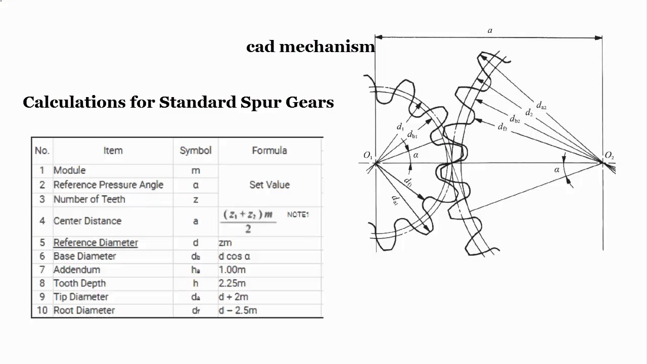
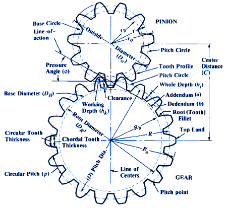
To calculate spur gear, you need to understand the basic parameters involved in its design. The calculation involves determining the pitch diameter, pitch circle, and tooth thickness of the gear. The pitch diameter is the diameter of the pitch circle, which is the circle that passes through the center of the teeth of the gear. The pitch circle is used as a reference to calculate the tooth spacing and pressure angle. The tooth thickness is the width of the tooth measured along the pitch circle.
Understanding Spur Gear Terminology
To calculate spur gear, it is essential to understand the terminology involved. The key terms include pitch diameter, pitch circle, tooth thickness, module, and pressure angle. The module is the ratio of the pitch diameter to the number of teeth, and it is used to determine the tooth size. The pressure angle is the angle between the line of action and the tangent to the pitch circle. The calculation of these parameters involves using formulas and equations that relate the gear parameters to each other.
- The pitch diameter is calculated using the formula: pitch diameter = (number of teeth x module) / (π x 2)
- The tooth thickness is calculated using the formula: tooth thickness = (module x π) / 2
- The pressure angle is calculated using the formula: pressure angle = arctan (tan (pressure angle) x (module / pitch diameter))
Calculating Spur Gear Ratios
The gear ratio is an essential parameter in calculating spur gear. The gear ratio is the ratio of the output speed to the input speed. It is calculated using the formula: gear ratio = (number of teeth of output gear) / (number of teeth of input gear). The gear ratio determines the torque and speed of the output shaft. A higher gear ratio results in a higher torque and lower speed, while a lower gear ratio results in a lower torque and higher speed.
- The gear ratio is calculated using the formula: gear ratio = (number of teeth of output gear) / (number of teeth of input gear)
- The torque is calculated using the formula: torque = (power x gear ratio) / (2 x π x speed)
- The speed is calculated using the formula: speed = (power x 2 x π) / (torque x gear ratio)
Determining Spur Gear Materials
The material of the spur gear is an essential factor in its calculation. The material properties, such as density, strength, and hardness, affect the gear performance. The most common materials used for spur gears are steel, aluminum, and brass. The material selection depends on the application, load, and environment.
- The steel material is suitable for high load and high speed applications
- The aluminum material is suitable for low load and low speed applications
- The brass material is suitable for corrosive environments and low load applications
Calculating Spur Gear Efficiency
The efficiency of the spur gear is an essential parameter in its calculation. The efficiency is the ratio of the output power to the input power. It is affected by the gear ratio, tooth thickness, and pressure angle. A higher efficiency results in a higher output power and lower heat generation.
- The efficiency is calculated using the formula: efficiency = (output power) / (input power)
- The output power is calculated using the formula: output power = (torque x speed) / (2 x π)
- The input power is calculated using the formula: input power = (torque x speed) / (2 x π x gear ratio)
Designing Spur Gear Using Software
The design of the spur gear can be done using software such as CAD and CAE. The software provides tools and features to create and analyze the gear model. The design involves creating the gear geometry, meshing, and contact analysis. The software also provides optimization tools to improve the gear performance and efficiency.
- The CAD software is used to create the gear geometry and model
- The CAE software is used to analyze the gear performance and efficiency
- The optimization tools are used to improve the gear performance and efficiency
What is the force analysis of a spur gear?
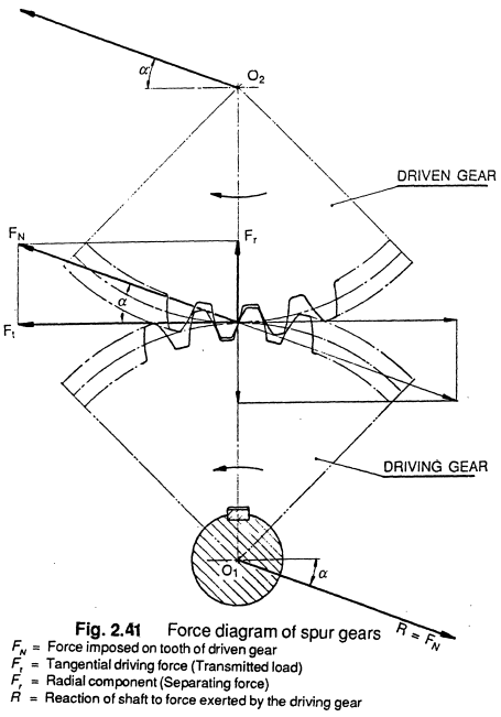
The force analysis of a spur gear is a critical aspect of gear design and mechanism analysis. It involves calculating the forces and torques acting on the gear teeth, as well as the stresses and deflections that occur due to these forces. This analysis is essential to ensure that the gear can withstand the loads and stresses imposed on it, and to optimize its performance and efficiency.
Introduction to Gear Force Analysis
The force analysis of a spur gear is a complex process that requires a thorough understanding of mechanics and mathematics. It involves calculating the normal forces, tangential forces, and radial forces acting on the gear teeth, as well as the torques and moments that occur due to these forces. The analysis is typically performed using computer-aided design (CAD) software and finite element analysis (FEA) techniques. Some key considerations in gear force analysis include:
- Material properties: The strength, stiffness, and density of the gear material must be considered in the analysis.
- Gear geometry: The pitch circle diameter, tooth width, and tooth profile of the gear must be accurately modeled.
- Load conditions: The types and magnitudes of loads that the gear will experience must be specified and analyzed.
- Normal force: The normal force is the force acting perpendicular to the tooth surface.
- Tangential force: The tangential force is the force acting parallel to the tooth surface.
- Radial force: The radial force is the force acting towards the center of the gear.
- Bending stress: The bending stress is the stress that occurs due to the bending moment acting on the gear tooth.
- Contact stress: The contact stress is the stress that occurs due to the contact force acting on the gear tooth.
- Root stress: The root stress is the stress that occurs at the root of the gear tooth.
- Wear: The wear of the gear teeth can occur due to the frictional forces acting on the gear.
- Fatigue: The fatigue of the gear teeth can occur due to the repeated loading and unloading of the gear.
- Efficiency: The efficiency of the gear can be affected by the forces and stresses acting on the gear.
- Geometry optimization: The gear geometry can be optimized to minimize the forces and stresses acting on the gear.
- Material selection: The material properties can be selected to minimize the forces and stresses acting on the gear.
- Load optimization: The load conditions can be optimized to minimize the forces and stresses acting on the gear.
- The number of teeth on each gear
- The diameter of each gear
- The speed of the input gear
- The type of gear system being used
- The material of the gears
- The load on the gear system
- The required gear ratio
- The space available for the gear system
- The load on the gear system
- The required gear ratio
- The desired gear speed
- The available space for the gear system
- The required gear ratio
- The desired efficiency of the gear system
- The module is a measure of the gear's tooth size and spacing
- The pitch is a measure of the gear's tooth density and _profile
- The number of teeth affects the gear's torque capacity and speed
- The module is a standardized value that ensures compatibility between gears
- The number of teeth affects the gear's torque capacity and speed
- The PCD calculation is critical for gear design and manufacturing
- The pitch is a measure of the gear's tooth density and profile
- The number of teeth affects the gear's torque capacity and speed
- The PCD calculation is critical for gear design and manufacturing
- Accurate PCD calculation ensures efficient gear operation
- Inaccurate PCD calculation can result in inefficient gear operation and increased wear
- Standardized calculations ensure compatibility between gears
- Gear design requires accurate PCD calculation to ensure efficient gear operation
- Gear manufacturing requires accurate PCD calculation to ensure precise machining and assembly
- Gear inspection requires accurate PCD calculation to verify the gear's dimensions and performance
Calculation of Gear Forces
The calculation of gear forces involves determining the normal forces, tangential forces, and radial forces acting on the gear teeth. These forces can be calculated using the equations of motion and the principles of mechanics. The force analysis must take into account the gear ratio, tooth profile, and load conditions. Some key calculations in gear force analysis include:
Analysis of Gear Stresses
The analysis of gear stresses involves determining the bending stresses, contact stresses, and root stresses that occur in the gear teeth. These stresses can be calculated using finite element analysis (FEA) and computer-aided design (CAD) software. The stress analysis must take into account the material properties, gear geometry, and load conditions. Some key considerations in gear stress analysis include:
Effects of Gear Forces on Gear Performance
The gear forces and stresses can have a significant impact on the performance and efficiency of the gear. High forces and stresses can lead to wear, fatigue, and failure of the gear, while low forces and stresses can result in inefficient operation and reduced performance. Some key effects of gear forces on gear performance include:
Optimization of Gear Design using Force Analysis
The force analysis of a spur gear can be used to optimize the design of the gear, by minimizing the forces and stresses acting on the gear teeth. This can be achieved by modifying the gear geometry, material properties, and load conditions. Some key optimization techniques include:
What is the formula for calculating gears?

The formula for calculating gears is based on the concept of gear ratio, which is the relationship between the number of teeth on two gears that are meshed together. The gear ratio is calculated by dividing the number of teeth on the output gear (the gear that is driven) by the number of teeth on the input gear (the gear that is driving). This ratio determines the torque and speed of the output gear.
Understanding Gear Ratio
The gear ratio is a critical factor in determining the performance of a gear system. A higher gear ratio means that the output gear will rotate more slowly than the input gear, but with increased torque. A lower gear ratio means that the output gear will rotate more quickly than the input gear, but with decreased torque. Some key points to consider when calculating gear ratio include:
Calculating Gear Ratio
To calculate the gear ratio, you need to know the number of teeth on each gear. The formula is: Gear Ratio = Number of teeth on output gear / Number of teeth on input gear. For example, if the output gear has 40 teeth and the input gear has 20 teeth, the gear ratio would be 2:1. This means that for every one rotation of the input gear, the output gear will rotate twice. Some key factors to consider when calculating gear ratio include:
Types of Gear Systems
There are several types of gear systems, each with its own unique characteristics and applications. Some common types of gear systems include spur gears, helical gears, and bevel gears. Each type of gear system has its own advantages and disadvantages, and the choice of which to use will depend on the specific application. Some key points to consider when selecting a gear system include:
Design Considerations
When designing a gear system, there are several factors to consider, including the gear material, gear shape, and gear size. The choice of gear material will depend on the operating conditions of the gear system, such as the temperature and load. The gear shape and size will also impact the performance of the gear system, and must be carefully selected to meet the required specifications. Some key points to consider when designing a gear system include:
Applications of Gear Systems
Gear systems are used in a wide range of applications, from automotive to industrial and aerospace. In each of these applications, the gear system plays a critical role in transmitting power and controlling speed. Some key points to consider when selecting a gear system for a specific application include:
How to calculate PCD of spur gear?
To calculate the Pitch Circle Diameter (PCD) of a spur gear, you need to know the number of teeth and the module or pitch of the gear. The PCD is the diameter of the circle that passes through the centers of the teeth, and it can be calculated using the following formula: PCD = (number of teeth x module) or PCD = (number of teeth x pitch / π). This calculation is crucial in gear design and manufacturing, as it determines the tooth profile and the overall gear performance.
Understanding Gear Terminology
To calculate the PCD of a spur gear, it's essential to understand the terminology used in gear design. This includes terms such as module, pitch, number of teeth, and tooth profile. The module is the ratio of the pitch diameter to the number of teeth, while the pitch is the distance between corresponding points on adjacent teeth. The number of teeth is the total number of teeth on the gear, and the tooth profile refers to the shape and size of the teeth. Some key points to consider include:
Calculating PCD Using Module
When calculating the PCD using the module, you need to know the number of teeth and the module value. The formula is PCD = (number of teeth x module), and this calculation provides the pitch circle diameter of the gear. This method is commonly used in gear design and manufacturing, as it allows for easy calculation of the gear's tooth profile and performance. Some key points to consider include:
Calculating PCD Using Pitch
When calculating the PCD using the pitch, you need to know the number of teeth and the pitch value. The formula is PCD = (number of teeth x pitch / π), and this calculation provides the pitch circle diameter of the gear. This method is commonly used in gear design and manufacturing, as it allows for easy calculation of the gear's tooth profile and performance. Some key points to consider include:
Importance of Accurate PCD Calculation
Accurate calculation of the PCD is crucial in gear design and manufacturing, as it affects the tooth profile and the overall gear performance. A small error in the PCD calculation can result in inefficient gear operation, increased wear, and reduced lifespan. Therefore, it's essential to use precise values and standardized calculations to ensure accurate results. Some key points to consider include:
Applications of PCD Calculation
The PCD calculation has various applications in gear design and manufacturing, including gear design, gear manufacturing, and gear inspection. In gear design, the PCD calculation is used to determine the tooth profile and the overall gear performance. In gear manufacturing, the PCD calculation is used to ensure accurate machining and assembly of the gear. In gear inspection, the PCD calculation is used to verify the gear's dimensions and performance. Some key points to consider include:
Frequently Asked Questions (FAQs)
What is the Force Analysis Spur Gears Equation and Calculator used for?
The Force Analysis Spur Gears Equation and Calculator is a tool used to calculate the forces and torques acting on spur gears in a mechanical system. This calculator is essential in the design and analysis of gear systems, as it helps engineers and designers to determine the load capacity and efficiency of the gears. The calculator takes into account various parameters such as the gear ratio, pitch circle diameter, face width, and material properties to calculate the tangential force, radial force, and axial force acting on the gears. By using this calculator, designers can optimize the design of the gear system to ensure smooth operation, high efficiency, and long lifespan.
How does the Force Analysis Spur Gears Equation and Calculator work?
The Force Analysis Spur Gears Equation and Calculator works by using a set of mathematical equations that describe the kinematics and dynamics of spur gears. The calculator first calculates the gear ratio and pitch circle diameter based on the input parameters, and then uses these values to calculate the tangential force, radial force, and axial force acting on the gears. The calculator also takes into account the friction and efficiency of the gear system, which can be affected by factors such as lubrication, surface finish, and material properties. The calculator uses numerical methods to solve the equations and provide accurate results. The output of the calculator includes the forces and torques acting on the gears, as well as other relevant parameters such as the contact stress and bending stress.
What are the key parameters that need to be input into the Force Analysis Spur Gears Equation and Calculator?
The key parameters that need to be input into the Force Analysis Spur Gears Equation and Calculator include the gear ratio, pitch circle diameter, face width, material properties, and operating conditions. The gear ratio is the ratio of the number of teeth on the driven gear to the number of teeth on the driving gear. The pitch circle diameter is the diameter of the pitch circle, which is the circle that passes through the center of each tooth. The face width is the width of the gear tooth, and the material properties include the elastic modulus, Poisson's ratio, and density of the gear material. The operating conditions include the rotational speed, torque, and power transmitted by the gear system. These parameters are essential in determining the forces and torques acting on the gears, and must be accurately input into the calculator to obtain reliable results.
What are the benefits of using the Force Analysis Spur Gears Equation and Calculator in gear design and analysis?
The benefits of using the Force Analysis Spur Gears Equation and Calculator in gear design and analysis include the ability to optimize the design of the gear system for high efficiency, low noise, and long lifespan. The calculator helps designers to predict the forces and torques acting on the gears, and to identify potential problems such as overloading, wear, and failure. The calculator also enables designers to compare different design options and to select the most suitable design for the specific application. Additionally, the calculator can be used to validate the design of existing gear systems, and to troubleshoot problems that may arise during operation. By using the Force Analysis Spur Gears Equation and Calculator, designers can save time and reduce costs associated with prototyping and testing, and can improve the overall performance and reliability of the gear system.
Deja una respuesta
Entradas Relacionadas