
Piston Slider Crank Mechanism Design Equations and Calculator
The Piston Slider Crank Mechanism is a fundamental component in various mechanical systems, including internal combustion engines and reciprocating compressors. Its design involves complex calculations to ensure optimal performance, efficiency, and reliability. The mechanism's dynamic behavior is influenced by various parameters, such as piston diameter, stroke length, and crankshaft speed. This article provides a comprehensive overview of the design equations and calculations involved in the Piston Slider Crank Mechanism, along with a calculator tool to simplify the process and facilitate accurate design decisions. Key design considerations and equations will be discussed in detail.
- Piston Slider Crank Mechanism Design Equations and Calculator
- What is the formula for the crank and slider mechanism?
- What is the formula for crank angularity?
- What is the construction of slider-crank mechanism?
-
Frequently Asked Questions (FAQs)
- What is the Piston Slider Crank Mechanism and its importance in engineering design?
- What are the key design equations and parameters involved in the Piston Slider Crank Mechanism?
- How do design calculators and software tools facilitate the design and analysis of the Piston Slider Crank Mechanism?
- What are the practical applications and limitations of the Piston Slider Crank Mechanism in real-world engineering systems?
Piston Slider Crank Mechanism Design Equations and Calculator
The Piston Slider Crank Mechanism is a fundamental component in various mechanical systems, including internal combustion engines, pumps, and compressors. The design of this mechanism involves the calculation of various parameters, such as the crank radius, connecting rod length, and piston diameter, to ensure optimal performance and efficiency. The use of design equations and calculators can facilitate the process of designing and optimizing the Piston Slider Crank Mechanism.
Introduction to Piston Slider Crank Mechanism
The Piston Slider Crank Mechanism consists of a crankshaft, connecting rod, and piston, which work together to convert rotational energy into linear motion. The mechanism is commonly used in internal combustion engines, where the piston moves up and down in the cylinder, driven by the crankshaft. The design of the Piston Slider Crank Mechanism requires careful consideration of various parameters, including the crank radius, connecting rod length, and piston diameter.
Design Equations for Piston Slider Crank Mechanism
The design of the Piston Slider Crank Mechanism involves the use of various design equations, which can be used to calculate the kinematic and dynamic parameters of the mechanism. Some of the key design equations include:
| Equation | Description |
|---|---|
| V = (π/4) d^2 L | Displacement volume equation, where V is the displacement volume, d is the piston diameter, and L is the stroke length |
| P = (2 π N) / 60 | Angular velocity equation, where P is the angular velocity, N is the rotational speed, and 60 is a constant |
These equations can be used to calculate the performance and efficiency of the Piston Slider Crank Mechanism.
Calculator for Piston Slider Crank Mechanism
A calculator can be used to simplify the process of designing and optimizing the Piston Slider Crank Mechanism. The calculator can be used to input various parameters, such as the crank radius, connecting rod length, and piston diameter, and calculate the kinematic and dynamic parameters of the mechanism. The calculator can also be used to visualize the motion of the mechanism and analyze its performance.
Applications of Piston Slider Crank Mechanism
The Piston Slider Crank Mechanism has a wide range of applications in various fields, including:
| Application | Description |
|---|---|
| Internal combustion engines | Internal combustion engines use the Piston Slider Crank Mechanism to convert chemical energy into mechanical energy |
| Pumps and compressors | Pumps and compressors use the Piston Slider Crank Mechanism to convert rotational energy into fluid energy |
The mechanism is also used in other applications, such as air motors and hydraulic systems.
Optimization of Piston Slider Crank Mechanism
The optimization of the Piston Slider Crank Mechanism involves the use of various techniques, such as finite element analysis and computational fluid dynamics, to improve its performance and efficiency. The optimization process can be used to minimize the weight and cost of the mechanism, while maximizing its power and efficiency. The use of computer-aided design (CAD) software can also facilitate the optimization process by allowing designers to simulate and analyze the behavior of the mechanism. Optimization is an essential step in the design of the Piston Slider Crank Mechanism, as it can help to improve the overall performance and reliability of the mechanism.
What is the formula for the crank and slider mechanism?

The formula for the crank and slider mechanism is a complex set of equations that describe the motion of the mechanism. The kinematics of the mechanism can be described by the following equations:
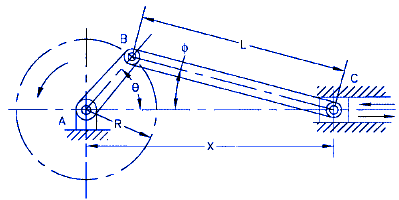
- The displacement of the slider is given by the equation: s = r (1 - cos(θ)) + l cos(θ),
- where s is the displacement of the slider, r is the radius of the crank, θ is the angle of rotation of the crank, and l is the length of the connecting rod.
- The velocity of the slider is given by the equation: v = r ω sin(θ) - l ω sin(θ),
- where v is the velocity of the slider, ω is the angular velocity of the crank.
- The acceleration of the slider is given by the equation: a = r α sin(θ) - l α sin(θ) - r ω^2 cos(θ) + l ω^2 cos(θ),
- where a is the acceleration of the slider, α is the angular acceleration of the crank.
Introduction to Crank and Slider Mechanism
The crank and slider mechanism is a type of mechanical linkage that converts rotary motion into linear motion. The mechanism consists of a crank, a connecting rod, and a slider. The crank is connected to a rotating shaft, and the connecting rod is connected to the slider. As the crank rotates, it pushes or pulls the slider back and forth. The crank and slider mechanism is commonly used in internal combustion engines, pumps, and compressors.
- Crank: The crank is the component that converts the rotary motion into linear motion.
- Connecting rod: The connecting rod is the component that connects the crank to the slider.
- Slider: The slider is the component that moves back and forth as the crank rotates.
Kinematics of Crank and Slider Mechanism
The kinematics of the crank and slider mechanism can be described by a set of equations that relate the displacement, velocity, and acceleration of the slider to the angle of rotation of the crank. These equations can be used to analyze and design the mechanism.
- Displacement: The displacement of the slider is given by the equation: s = r (1 - cos(θ)) + l cos(θ).
- Velocity: The velocity of the slider is given by the equation: v = r ω sin(θ) - l ω sin(θ).
- Acceleration: The acceleration of the slider is given by the equation: a = r α sin(θ) - l α sin(θ) - r ω^2 cos(θ) + l ω^2 cos(θ).
Dynamic Analysis of Crank and Slider Mechanism
The dynamic analysis of the crank and slider mechanism involves the study of the forces and moments that act on the mechanism. This includes the inertia forces, friction forces, and external forces that act on the mechanism. The dynamic analysis is used to design and optimize the mechanism.
- Inertia forces: The inertia forces are the forces that act on the mechanism due to the acceleration of the slider.
- Friction forces: The friction forces are the forces that act on the mechanism due to the friction between the slider and the guide.
- External forces: The external forces are the forces that act on the mechanism due to the external loads.
Design Considerations for Crank and Slider Mechanism
The design of the crank and slider mechanism involves the selection of the dimensions and materials of the components. The design must take into account the requirements of the mechanism, such as the displacement, velocity, and acceleration of the slider.
- Dimensions: The dimensions of the mechanism must be selected to achieve the required displacement, velocity, and acceleration of the slider.
- Materials: The materials of the components must be selected to withstand the forces and moments that act on the mechanism.
- Manufacturing: The manufacturing process must be selected to produce the components with the required tolerances and surface finish.
Applications of Crank and Slider Mechanism
The crank and slider mechanism has a wide range of applications in mechanical engineering. It is commonly used in internal combustion engines, pumps, and compressors. The mechanism is also used in machine tools, robots, and automated systems.
- Internal combustion engines: The crank and slider mechanism is used in internal combustion engines to convert the rotary motion of the crankshaft into linear motion of the pistons.
- Pumps: The crank and slider mechanism is used in pumps to convert the rotary motion of the motor into linear motion of the piston.
- Compressors: The crank and slider mechanism is used in compressors to convert the rotary motion of the motor into linear motion of the piston.
What is the formula for crank angularity?
The formula for crank angularity is not a straightforward calculation, as it depends on various factors such as the type of engine, crankshaft design, and piston configuration. However, the general concept of crank angularity refers to the angle between the crankpin and the crankshaft centerline. This angle is critical in determining the engine's performance, efficiency, and vibrational characteristics.
Understanding Crank Angularity
Crank angularity is a critical parameter in internal combustion engines, as it affects the piston's motion, connecting rod stress, and crankshaft dynamics. The crank angularity is influenced by the crankshaft's design, including the crankpin offset, main bearing diameter, and counterweight design. To calculate the crank angularity, engineers use computer-aided design (CAD) software and finite element analysis (FEA) to simulate the engine's behavior and optimize the crankshaft design.
- Crankpin offset and diameter
- Main bearing diameter and type
- Counterweight design and location
Factors Affecting Crank Angularity
Several factors affect the crank angularity, including the engine's operating conditions, such as speed, load, and temperature. The crankshaft's material properties, including density, elasticity, and damping, also influence the crank angularity. Additionally, the piston's design, including the piston pin offset and ring design, can impact the crank angularity.
- Engine speed and load
- Crankshaft material properties
- Piston design and ring package
Crank Angularity Calculation
To calculate the crank angularity, engineers use a combination of analytical and numerical methods. The analytical approach involves using mathematical models to predict the crank angularity based on the engine's design parameters. The numerical approach involves using computer simulations to model the engine's behavior and calculate the crank angularity.
- Mathematical modeling of the engine's design
- Computer simulations of the engine's behavior
- Experimental validation of the calculated crank angularity
Importance of Crank Angularity
The crank angularity is a critical parameter in engine design, as it affects the engine's performance, efficiency, and vibrational characteristics. A well-designed crankshaft with optimal crank angularity can improve the engine's power output, fuel efficiency, and reliability. Conversely, a poorly designed crankshaft with inadequate crank angularity can lead to engine vibration, noise, and premature wear.
- Engine performance and power output
- Fuel efficiency and emissions
- Reliability and durability
Challenges in Crank Angularity Optimization
Optimizing the crank angularity is a challenging task, as it requires balancing multiple conflicting factors, such as engine performance, efficiency, and vibrational characteristics. The crankshaft's design must be optimized to achieve the optimal crank angularity, while also considering manufacturing constraints and cost. Additionally, the engine's operating conditions must be considered to ensure that the crank angularity is optimized for the entire operating range.
- Balancing conflicting design factors
- Manufacturing constraints and cost
- Engine operating conditions and range
What is the construction of slider-crank mechanism?
The construction of a slider-crank mechanism is a type of mechanical linkage that is commonly used in internal combustion engines, pumps, and other machines. It consists of a crankshaft that converts reciprocating motion into rotary motion, a connecting rod that connects the crankshaft to a piston, and a slider that moves linearly along a fixed axis. The crankshaft is the main component of the mechanism, and it is typically driven by a motor or an engine. The connecting rod is attached to the crankshaft at one end and to the piston at the other end, and it converts the rotary motion of the crankshaft into reciprocating motion of the piston.
Components of a Slider-Crank Mechanism
The components of a slider!creank mechanism include the crankshaft, connecting rod, piston, and slider. These components work together to convert reciprocating motion into rotary motion. Some of the key features of these components include:
- Crankshaft: The crankshaft is the main component of the mechanism, and it is typically driven by a motor or an engine.
- Connecting rod: The connecting rod is attached to the crankshaft at one end and to the piston at the other end, and it converts the rotary motion of the crankshaft into reciprocating motion of the piston.
- Piston: The piston is the component that moves linearly along a fixed axis, and it is typically attached to the connecting rod.
Working of a Slider-Crank Mechanism
The working of a slider-crank mechanism involves the conversion of reciprocating motion into rotary motion. As the crankshaft rotates, it causes the connecting rod to move linearly, which in turn causes the piston to move linearly along a fixed axis. This motion is then converted back into rotary motion by the crankshaft, creating a continuous cycle of motion. Some of the key features of this process include:
- Rotary motion: The crankshaft rotates, causing the connecting rod to move linearly.
- Linear motion: The connecting rod moves linearly, causing the piston to move linearly along a fixed axis.
- Conversion of motion: The linear motion of the piston is converted back into rotary motion by the crankshaft.
Applications of a Slider-Crank Mechanism
The slider-crank mechanism has a wide range of applications in various fields, including internal combustion engines, pumps, and other machines. Some of the key features of these applications include:
- Internal combustion engines: The slider-crank mechanism is used to convert the reciprocating motion of the pistons into rotary motion of the crankshaft.
- Pumps: The slider-crank mechanism is used to convert the rotary motion of the motor into linear motion of the piston.
- Other machines: The slider-crank mechanism is used in other machines, such as compressors and generators.
Advantages of a Slider-Crank Mechanism
The slider-crank mechanism has several advantages, including high efficiency, low cost, and simple design. Some of the key features of these advantages include:
- High efficiency: The slider-crank mechanism is able to convert reciprocating motion into rotary motion with high efficiency.
- Low cost: The slider-crank mechanism is relatively inexpensive to manufacture and maintain.
- Simple design: The slider-crank mechanism has a simple design, making it easy to understand and maintain.
Design Considerations of a Slider-Crank Mechanism
The design considerations of a slider-crank mechanism include the selection of materials, dimensioning of components, and analysis of motion. Some of the key features of these considerations include:
- Selection of materials: The selection of materials for the components of the slider-crank mechanism is critical to ensure high performance and long life.
- Dimensioning of components: The dimensioning of components is critical to ensure proper fit and smooth motion.
- Analysis of motion: The analysis of motion is critical to ensure high efficiency and low vibration.
Frequently Asked Questions (FAQs)
What is the Piston Slider Crank Mechanism and its importance in engineering design?
The Piston Slider Crank Mechanism is a fundamental component in mechanical engineering, widely used in various applications such as internal combustion engines, pumps, and compressors. This mechanism consists of a crankshaft, a connecting rod, a piston, and a slider, which work together to convert rotational motion into linear motion or vice versa. The importance of this mechanism lies in its ability to provide a smooth and efficient transfer of energy, making it a crucial element in the design of many mechanical systems. The design equations and calculators used for this mechanism play a vital role in determining the optimal parameters and performance characteristics of the system, ensuring that it operates within the desired tolerances and efficiency standards.
What are the key design equations and parameters involved in the Piston Slider Crank Mechanism?
The design equations for the Piston Slider Crank Mechanism involve a set of complex mathematical formulas that take into account various parameters such as the crank radius, connecting rod length, piston diameter, and slider stroke. These equations are used to calculate performance characteristics like the mechanical advantage, efficiency, and power output of the system. The key parameters involved in the design of this mechanism include the kinematic and dynamic properties of the system, such as the angular velocity and torque of the crankshaft, the linear velocity and acceleration of the piston, and the force and pressure exerted on the slider. By carefully analyzing and optimizing these parameters using design calculators and software tools, engineers can ensure that the Piston Slider Crank Mechanism operates at its optimal performance and efficiency.
How do design calculators and software tools facilitate the design and analysis of the Piston Slider Crank Mechanism?
Design calculators and software tools play a vital role in the design and analysis of the Piston Slider Crank Mechanism by providing fast and accurate calculations of the design equations and performance characteristics. These tools enable engineers to model and simulate the behavior of the mechanism under various operating conditions, allowing them to optimize the design and predict the performance of the system. By using computer-aided design (CAD) software and finite element analysis (FEA) tools, engineers can create detailed models of the mechanism and analyze its stress, strain, and vibration characteristics, ensuring that the design meets the required safety and performance standards. Additionally, these tools facilitate the comparison of different design options and scenarios, enabling engineers to make informed decisions and iterate on the design until the optimal solution is achieved.
What are the practical applications and limitations of the Piston Slider Crank Mechanism in real-world engineering systems?
The Piston Slider Crank Mechanism has numerous practical applications in real-world engineering systems, including internal combustion engines, pumps, compressors, and mechanical presses. In these applications, the mechanism is used to convert energy from one form to another, providing a reliable and efficient means of power transmission. However, the mechanism also has some limitations, such as friction and wear on the moving parts, which can lead to reduced efficiency and increased maintenance costs. Additionally, the mechanism can be sensitive to imbalances and vibrations, which can affect its performance and reliability. To overcome these limitations, engineers use advanced materials and design techniques, such as surface coatings and dynamic balancing, to minimize friction and maximize efficiency. By understanding the practical applications and limitations of the Piston Slider Crank Mechanism, engineers can design and optimize real-world engineering systems that meet the required performance and reliability standards.
Deja una respuesta
Entradas Relacionadas