
Pipe Flow Gradual Size Enlargement Formula and Calculator

The pipe flow gradual size enlargement formula is a crucial concept in fluid dynamics, particularly in the design and optimization of piping systems. When a pipe enlarges gradually, the flow rate and pressure drop are affected, and this formula helps engineers calculate these changes. The gradual enlargement of a pipe can lead to a reduction in pressure drop and an increase in flow rate, making it an essential consideration in various industries, including chemical processing, power generation, and water supply. This article provides an overview of the formula and a calculator to simplify the calculation process.
- Pipe Flow Gradual Size Enlargement Formula and Calculator
- What is the manning equation for pipe flow?
- What is the Hazen Williams formula for pipe flow?
- How to calculate the full flow capacity of a pipe?
-
Frequently Asked Questions (FAQs)
- What is the Pipe Flow Gradual Size Enlargement Formula and how is it used?
- How does the Pipe Flow Gradual Size Enlargement Calculator work?
- What are the advantages of using the Pipe Flow Gradual Size Enlargement Formula and Calculator?
- What are the limitations and potential errors of the Pipe Flow Gradual Size Enlargement Formula and Calculator?
Pipe Flow Gradual Size Enlargement Formula and Calculator
The Pipe Flow Gradual Size Enlargement Formula and Calculator is a tool used to determine the flow rate and pressure drop in a pipe with a gradual size enlargement. This is a common occurrence in many piping systems, where a smaller pipe connects to a larger pipe, resulting in a change in flow velocity and pressure. The formula and calculator take into account the Darcy-Weisbach equation and the Colebrook-White equation to calculate the friction factor and head loss in the pipe.
Introduction to Pipe Flow Gradual Size Enlargement
Pipe flow gradual size enlargement occurs when a smaller pipe connects to a larger pipe, resulting in a change in flow velocity and pressure. This can lead to a pressure drop or head loss in the pipe, which can affect the overall performance of the system. The Pipe Flow Gradual Size Enlargement Formula and Calculator is used to determine the flow rate and pressure drop in such systems.
Darcy-Weisbach Equation and Friction Factor
The Darcy-Weisbach equation is used to calculate the friction factor in a pipe, which is a measure of the resistance to flow in the pipe. The equation is given by: ΔP = (L/D) (f ρ V^2)/2, where ΔP is the pressure drop, L is the length of the pipe, D is the diameter of the pipe, f is the friction factor, ρ is the density of the fluid, and V is the velocity of the fluid.
Colebrook-White Equation and Head Loss
The Colebrook-White equation is used to calculate the head loss in a pipe, which is a measure of the energy lost due to friction in the pipe. The equation is given by: h_f = (L/D) (f V^2)/2g, where h_f is the head loss, L is the length of the pipe, D is the diameter of the pipe, f is the friction factor, V is the velocity of the fluid, and g is the acceleration due to gravity.
Calculating Flow Rate and Pressure Drop
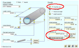
To calculate the flow rate and pressure drop in a pipe with a gradual size enlargement, the Pipe Flow Gradual Size Enlargement Formula and Calculator can be used. The calculator takes into account the diameter and length of the pipe, as well as the flow rate and pressure at the inlet and outlet of the pipe. The calculator then uses the Darcy-Weisbach equation and the Colebrook-White equation to calculate the friction factor and head loss in the pipe.
Applications of Pipe Flow Gradual Size Enlargement Formula and Calculator
The Pipe Flow Gradual Size Enlargement Formula and Calculator has a wide range of applications in many industries, including petroleum, chemical, and power generation. It can be used to design and optimize piping systems, as well as to troubleshoot problems with existing systems. The calculator can also be used to determine the energy losses in a piping system, which can help to reduce energy consumption and costs.
| Pipe Diameter | Pipe Length | Flow Rate | Pressure Drop | Friction Factor |
|---|---|---|---|---|
| 10 cm | 100 m | 1000 L/min | 10 kPa | 0.02 |
| 20 cm | 200 m | 2000 L/min | 20 kPa | 0.04 |
What is the manning equation for pipe flow?

The Manning equation for pipe flow is a widely used formula to calculate the velocity of fluid flow in pipelines. It is given by the equation: V = (1/n) R^2/3 S^1/2, where V is the velocity of the fluid, n is the Manning roughness coefficient, R is the hydraulic radius of the pipe, and S is the slope of the pipe.
Introduction to the Manning Equation
The Manning equation is a fundamental concept in fluid mechanics and is used to design and optimize pipeline systems. The equation takes into account the roughness of the pipe, the slope of the pipe, and the hydraulic radius of the pipe to calculate the velocity of the fluid. The Manning roughness coefficient is a key parameter in the equation and depends on the type of pipe material and its condition.
- The Manning roughness coefficient can vary from 0.01 to 0.03 for different types of pipes.
- The hydraulic radius is calculated as the cross-sectional area of the pipe divided by the wetted perimeter.
- The slope of the pipe is the angle at which the pipe is inclined, which affects the velocity of the fluid.
Applications of the Manning Equation
The Manning equation has numerous applications in civil engineering, including the design of stormwater drainage systems, sewer systems, and water distribution systems. The equation is also used to calculate the head loss in pipes, which is essential for designing pumping systems.
- The Manning equation can be used to calculate the flow rate in pipes, which is critical for designing water treatment plants.
- The equation is also used to calculate the velocity of fluid flow in open channels, such as rivers and canals.
- The Manning equation can be used to optimize the design of pipeline systems, reducing energy losses and increasing efficiency.
Limitations of the Manning Equation
Although the Manning equation is widely used, it has some limitations. The equation assumes that the flow is turbulent and steady, which may not always be the case. Additionally, the equation does not account for viscosity and surface tension effects, which can be significant in certain applications.
- The Manning equation is not suitable for laminar flow conditions, where the flow is smooth and continuous.
- The equation does not account for pipe fittings and valves, which can cause significant head losses.
- The Manning equation is not suitable for non-Newtonian fluids, which have complex rheological properties.
Derivation of the Manning Equation
The Manning equation was derived by Irish engineer Robert Manning in the late 19th century. The equation is based on experiments and observations of fluid flow in pipelines. The equation is a semi-empirical formula, meaning that it is based on a combination of theoretical and experimental results.
- The Manning equation is derived from the Chezy equation, which is a earlier formula for calculating velocity of fluid flow.
- The equation is based on the concept of hydraulic radius, which is the ratio of the cross-sectional area of the pipe to the wetted perimeter.
- The Manning equation is widely used due to its simplicity and accuracy, making it a fundamental tool in fluid mechanics.
Comparison with Other Equations
The Manning equation is one of several equations used to calculate the velocity of fluid flow in pipelines. Other equations, such as the Darcy-Weisbach equation and the Hazen-Williams equation, are also widely used. Each equation has its own advantages and disadvantages, and the choice of equation depends on the specific application.
- The Darcy-Weisbach equation is more accurate than the Manning equation, but it is also more complex.
- The Hazen-Williams equation is similar to the Manning equation, but it is more suitable for water distribution systems.
- The Manning equation is widely used due to its simplicity and ease of use, making it a popular choice for pipeline design.
What is the Hazen Williams formula for pipe flow?

The Hazen-Williams formula is an empirical equation that predicts the hydraulic gradient and flow rate of water flowing through a pipe under turbulent flow conditions. The formula is commonly used in the design of water distribution systems, sewer systems, and stormwater drainage systems. It is expressed as: h = (10.67 L Q^1.852) / (C^1.852 D^4.87), where h is the head loss, L is the length of the pipe, Q is the flow rate, C is the Hazen-Williams coefficient, and D is the diameter of the pipe.
Introduction to the Hazen-Williams Formula
The Hazen-Williams formula is a widely used equation in the field of civil engineering and hydraulics. It is used to calculate the head loss in a pipe due to friction and other energy losses. The formula takes into account the flow rate, pipe diameter, pipe length, and the Hazen-Williams coefficient, which is a measure of the roughness of the pipe. The formula is Empirical and is based on experimental data, and is generally accurate for turbulent flow conditions.
- The Hazen-Williams formula is used to design water distribution systems and sewer systems.
- The formula is also used to calculate the head loss in stormwater drainage systems.
- The Hazen-Williams coefficient is a critical parameter in the formula, and its value depends on the type of pipe and its condition.
Assumptions and Limitations of the Hazen-Williams Formula
The Hazen-Williams formula is based on several assumptions and has some limitations. It is assumed that the flow is turbulent, and the pipe is circular and horizontal. The formula is also limited to water and other Newtonian fluids, and is not applicable to non-Newtonian fluids. Additionally, the formula does not account for energy losses due to bends, valves, and other fittings.
- The Hazen-Williams formula assumes turbulent flow conditions.
- The formula is limited to water and other Newtonian fluids.
- The Hazen-Williams coefficient must be determined experimentally or from empirical data.
Derivation of the Hazen-Williams Formula
The Hazen-Williams formula is derived from empirical data and is based on the Darcy-Weisbach equation. The Darcy-Weisbach equation is a theoretical equation that describes the head loss in a pipe due to friction. The Hazen-Williams formula is a simplified version of the Darcy-Weisbach equation, and is easier to use in practice.
- The Hazen-Williams formula is derived from empirical data.
- The formula is based on the Darcy-Weisbach equation.
- The Hazen-Williams coefficient is a critical parameter in the formula.
Applications of the Hazen-Williams Formula
The Hazen-Williams formula has several applications in the field of civil engineering and hydraulics. It is used to design water distribution systems, sewer systems, and stormwater drainage systems. The formula is also used to calculate the head loss in pipes and to determine the required pipe diameter for a given flow rate.
- The Hazen-Williams formula is used to design water distribution systems.
- The formula is used to calculate the head loss in pipes.
- The Hazen-Williams coefficient is used to determine the required pipe diameter.
Comparison with Other Formulas
The Hazen-Williams formula is one of several formulas used to calculate the head loss in pipes. Other formulas, such as the Darcy-Weisbach equation and the Manning equation, are also used in practice. The Hazen-Williams formula is generally easier to use and is more conservative than other formulas, but it is limited to turbulent flow conditions.
- The Hazen-Williams formula is one of several formulas used to calculate the head loss.
- The Darcy-Weisbach equation is a more theoretical equation.
- The Manning equation is used for open channel flow conditions.
How to calculate the full flow capacity of a pipe?
To calculate the full flow capacity of a pipe, you need to consider several factors, including the pipe's diameter, length, material, and the fluid being transported. The flow capacity of a pipe is typically measured in terms of its volume flow rate, which is the volume of fluid that can flow through the pipe per unit time. This can be calculated using the equation of continuity, which states that the volume flow rate is equal to the product of the cross-sectional area of the pipe and the velocity of the fluid.
Understanding Pipe Flow Dynamics
The flow dynamics of a pipe are crucial in determining its full flow capacity. The Reynolds number plays a significant role in determining the nature of the flow, whether it is laminar or turbulent. A high Reynolds number indicates turbulent flow, while a low Reynolds number indicates laminar flow. The flow dynamics can be affected by factors such as pipe roughness, bends, and valves. To calculate the full flow capacity, you need to consider the following:
- Pipe diameter and length are crucial in determining the flow capacity.
- Fluid properties, such as viscosity and density, affect the flow dynamics.
- Pipe material and surface roughness can also impact the flow capacity.
Calculating Volume Flow Rate
The volume flow rate can be calculated using the equation of continuity, which states that the volume flow rate is equal to the product of the cross-sectional area of the pipe and the velocity of the fluid. The cross-sectional area can be calculated using the formula for the area of a circle, which is πr^2, where r is the radius of the pipe. The velocity of the fluid can be calculated using the Darcy-Weisbach equation, which takes into account the friction factor and the length of the pipe. To calculate the volume flow rate, you need to consider the following:
- Cross-sectional area of the pipe is crucial in determining the volume flow rate.
- Velocity of the fluid affects the volume flow rate.
- Friction factor and length of the pipe also impact the volume flow rate.
Considering Fluid Properties
The properties of the fluid being transported, such as its viscosity and density, play a significant role in determining the full flow capacity of a pipe. Viscosity affects the friction factor, while density affects the velocity of the fluid. The fluid properties can be affected by factors such as temperature and pressure. To calculate the full flow capacity, you need to consider the following:
- Viscosity of the fluid affects the friction factor.
- Density of the fluid affects the velocity of the fluid.
- Temperature and pressure can impact the fluid properties.
Pipe losses, such as friction losses and minor losses, can significantly impact the full flow capacity of a pipe. Friction losses occur due to the viscosity of the fluid and the roughness of the pipe, while minor losses occur due to bends, valves, and other fittings. To calculate the full flow capacity, you need to consider the following:
- Friction losses occur due to viscosity and roughness.
- Minor losses occur due to bends, valves, and other fittings.
- Pipe roughness and fittings can impact the pipe losses.
Using Pipe Flow Calculations in Practice
Pipe flow calculations are crucial in various industries, such as water supply, oil and gas, and chemical processing. The calculations can be used to design and optimize pipe systems, as well as to troubleshoot problems. To calculate the full flow capacity, you need to consider the following:
- Design and optimization of pipe systems require accurate calculations.
- Troubleshooting problems requires understanding of pipe flow dynamics.
- Industry standards and regulations must be followed in pipe flow calculations.
Frequently Asked Questions (FAQs)
What is the Pipe Flow Gradual Size Enlargement Formula and how is it used?
The Pipe Flow Gradual Size Enlargement Formula is a mathematical equation used to calculate the pressure drop and flow rate in a pipe with a gradual enlargement in size. This formula is essential in various engineering applications, such as pipeline design, fluid transportation, and hydraulic systems. The formula takes into account the velocity of the fluid, the diameter of the pipe, and the roughness of the pipe wall. By using this formula, engineers can determine the optimal pipe size and configuration to minimize energy losses and ensure efficient fluid flow. The Pipe Flow Gradual Size Enlargement Formula is a powerful tool for designing and optimizing pipeline systems, and its applications are diverse, ranging from water supply and sewage systems to oil and gas transportation.
How does the Pipe Flow Gradual Size Enlargement Calculator work?
The Pipe Flow Gradual Size Enlargement Calculator is a software tool that uses the Pipe Flow Gradual Size Enlargement Formula to calculate the pressure drop and flow rate in a pipe with a gradual enlargement in size. The calculator requires input values such as the pipe diameter, fluid velocity, pipe roughness, and fluid properties, and then uses these values to calculate the pressure drop and flow rate. The calculator can also be used to determine the optimal pipe size and configuration to minimize energy losses and ensure efficient fluid flow. The calculator is user-friendly and provides accurate results, making it an essential tool for engineers and designers working on pipeline projects. The calculator can also be used to analyze and optimize existing pipeline systems, helping to improve performance and reduce costs.
What are the advantages of using the Pipe Flow Gradual Size Enlargement Formula and Calculator?
The Pipe Flow Gradual Size Enlargement Formula and Calculator offer several advantages in pipeline design and optimization. One of the main advantages is the ability to accurately predict the pressure drop and flow rate in a pipe with a gradual enlargement in size. This allows engineers to optimize pipe size and configuration to minimize energy losses and ensure efficient fluid flow. Another advantage is the ability to analyze and optimize existing pipeline systems, helping to improve performance and reduce costs. The formula and calculator also provide a quick and easy way to design and optimize pipeline systems, saving time and resources. Additionally, the formula and calculator can be used to evaluate the performance of different pipe materials and configurations, helping to select the most suitable options for a particular application.
What are the limitations and potential errors of the Pipe Flow Gradual Size Enlargement Formula and Calculator?
The Pipe Flow Gradual Size Enlargement Formula and Calculator have some limitations and potential errors that need to be considered. One of the main limitations is the assumption of a steady-state flow, which may not be valid in all applications. Another limitation is the simplification of the fluid flow and pipe wall interactions, which can lead to inaccurate results in some cases. The calculator also requires accurate input values, and any errors in these values can lead to inaccurate results. Additionally, the formula and calculator do not take into account other factors that can affect pipeline performance, such as valves, fittings, and pumps. Therefore, it is essential to carefully evaluate the results and consider other factors when using the Pipe Flow Gradual Size Enlargement Formula and Calculator to design and optimize pipeline systems. Regular updates and validation of the formula and calculator are also necessary to ensure that they remain accurate and reliable.
Deja una respuesta
Entradas Relacionadas