
Pipe Bends Minimum Wall Thickness Calculator per. ASME B31.3
The Pipe Bends Minimum Wall Thickness Calculator is a crucial tool for engineers and designers working with piping systems, particularly those adhering to the ASME B31.3 standard. This standard provides guidelines for the design, construction, and installation of process piping systems. Calculating the minimum wall thickness of pipe bends is essential to ensure the structural integrity and safety of these systems, preventing potential failures due to corrosion, erosion, or other factors. Accurate calculations are vital for maintaining the reliability and efficiency of process piping. The calculator simplifies this process, offering a straightforward method for determining minimum wall thickness.
- Pipe Bends Minimum Wall Thickness Calculator per. ASME B31.3
- What is the formula for pipe thickness as per ASME B31 3?
- What is the minimum wall thickness for tube bending?
- What is the thickness tolerance for B31 3?
- What is the formula for wall thinning due to bending?
-
Frequently Asked Questions (FAQs)
- What is the purpose of the Pipe Bends Minimum Wall Thickness Calculator per ASME B31.3?
- How does the Pipe Bends Minimum Wall Thickness Calculator per ASME B31.3 account for different pipe materials and sizes?
- What are the key inputs and outputs of the Pipe Bends Minimum Wall Thickness Calculator per ASME B31.3?
- How can the Pipe Bends Minimum Wall Thickness Calculator per ASME B31.3 be used to optimize piping system design and ensure compliance with industry standards?
Pipe Bends Minimum Wall Thickness Calculator per. ASME B31.3
The Pipe Bends Minimum Wall Thickness Calculator is a tool used to calculate the minimum required wall thickness for pipe bends in accordance with the ASME B31.3 standard. This standard provides guidelines for the design, construction, and inspection of process piping systems. The calculator takes into account various factors such as the pipe size, bend radius, material, and operating conditions to determine the minimum wall thickness required to ensure the structural integrity of the pipe bend.
Introduction to ASME B31.3 Standard
The ASME B31.3 standard is a widely accepted guideline for the design, construction, and inspection of process piping systems. It provides requirements for the material selection, fabrication, erection, and testing of piping systems. The standard also includes guidelines for the calculation of pipe wall thickness and the determination of minimum wall thickness for pipe bends. The ASME B31.3 standard is used in various industries, including petrochemical, chemical, and power generation.
Factors Affecting Pipe Bend Wall Thickness
Several factors affect the minimum wall thickness required for pipe bends, including:
- Pipe size: The larger the pipe size, the thicker the wall thickness required.
- Bend radius: The smaller the bend radius, the thicker the wall thickness required.
- Material: The type of material used for the pipe affects the required wall thickness.
- Operating conditions: The temperature, pressure, and corrosion conditions of the piping system affect the required wall thickness.
Calculation Methodology
The calculation methodology for determining the minimum wall thickness of pipe bends involves the following steps:
- Determine the design conditions, including temperature, pressure, and corrosion.
- Select the material and determine its allowable stress.
- Calculate the required wall thickness using the ASME B31.3 formula.
- Apply safety factors and corrosion allowances to determine the minimum wall thickness.
Pipe Bend Design Considerations
When designing pipe bends, several considerations must be taken into account, including:
- Bend radius: The bend radius should be sufficient to prevent excessive stress and deformation.
- Supports: The pipe bend should be adequately supported to prevent sagging and vibration.
- Welding: The welding technique and joint design should be suitable for the material and operating conditions.
Importance of Minimum Wall Thickness
The minimum wall thickness of pipe bends is crucial to ensure the structural integrity and safety of the piping system. A minimum wall thickness that is too low can lead to pipe failure, leaks, and accidents. On the other hand, a minimum wall thickness that is too high can result in excessive material costs and increased weight.
| Factor | Description |
|---|---|
| Pipe Size | The diameter of the pipe, which affects the required wall thickness |
| Bend Radius | The radius of the pipe bend, which affects the required wall thickness |
| Material | The type of material used for the pipe, which affects the required wall thickness |
| Operating Conditions | The temperature, pressure, and corrosion conditions of the piping system, which affect the required wall thickness |
| Safety Factors | Factors applied to the calculated wall thickness to ensure safety and prevent failure |
What is the formula for pipe thickness as per ASME B31 3?

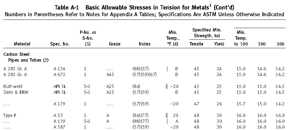
The formula for pipe thickness as per ASME B31.3 is given by the equation: t = (P D) / (2 S E - P), where t is the minimum required thickness, P is the internal pressure, D is the outside diameter, S is the allowable stress, and E is the joint efficiency.
Understanding the Variables
The variables in the equation are crucial to determining the minimum required thickness of the pipe. The internal pressure (P) is the maximum pressure that the pipe will be subjected to, and the allowable stress (S) is the maximum stress that the pipe material can withstand. The joint efficiency (E) is a factor that depends on the type of joint used in the pipe, and the outside diameter (D) is the diameter of the pipe. The following are the key considerations:
- Internal pressure (P) is a critical factor in determining the minimum required thickness of the pipe.
- Allowable stress (S) is determined based on the material of the pipe and its temperature.
- Joint efficiency (E) is a factor that depends on the type of joint used in the pipe, such as welded or threaded joints.
Calculating Minimum Required Thickness
To calculate the minimum required thickness, the values of the variables must be known. The internal pressure and allowable stress can be determined from the design specifications, and the joint efficiency can be determined from the type of joint used. The outside diameter (D) can be determined from the pipe size. The following steps are involved in calculating the minimum required thickness:
- Determine the internal pressure (P) and allowable stress (S) from the design specifications.
- Determine the joint efficiency (E) from the type of joint used.
- Calculate the minimum required thickness using the equation t = (P D) / (2 S E - P).
importance of Joint Efficiency
The joint efficiency (E) is a critical factor in determining the minimum required thickness of the pipe. The joint efficiency factor depends on the type of joint used in the pipe, such as welded or threaded joints. A higher joint efficiency factor indicates a stronger joint, which can withstand higher internal pressures. The following are the key considerations:
- Welded joints have a higher joint efficiency factor than threaded joints.
- Threaded joints have a lower joint efficiency factor due to the potential for leakage and weakness at the threads.
- Joint efficiency factor can be improved by using advanced welding techniques or by using high-strength thread compounds.
allowable Stress Values
The allowable stress values are determined based on the material of the pipe and its temperature. The allowable stress values are typically provided in the material specifications or can be determined through testing. The following are the key considerations:
- Allowable stress values decrease with increasing temperature.
- Allowable stress values increase with decreasing temperature.
- Allowable stress values can be affected by the presence of corrosive substances or other environmental factors.
Limitations of the Formula
The formula for pipe thickness as per ASME B31.3 has several limitations. The formula assumes that the pipe is subjected to internal pressure only and does not account for other loads such as external pressure, bending, or torsion. The following are the key considerations:
- The formula does not account for external pressure, which can cause the pipe to collapse.
- The formula does not account for bending or torsion, which can cause the pipe to fail.
- The formula assumes that the pipe material is isotropic, which may not be the case for all materials.
What is the minimum wall thickness for tube bending?

The minimum wall thickness for tube bending depends on various factors, including the material, diameter, and bend radius of the tube. Generally, a thicker wall provides more structural integrity and resistance to deformation, but it also increases the stiffness of the tube, making it more difficult to bend. The minimum wall thickness is usually determined by the manufacturer or designer based on the specific application and required properties of the bent tube.
Factors Affecting Minimum Wall Thickness
The minimum wall thickness for tube bending is influenced by several factors, including the material properties, tube diameter, and bend radius. The wall thickness must be sufficient to maintain the structural integrity of the tube during the bending process and to ensure the required strength and stability of the bent tube. Some key factors to consider are:
- The material properties, such as the yield strength and elongation, which affect the formability of the tube.
- The tube diameter, which influences the bend radius and the stress distribution during bending.
- The bend radius ...
Material Selection for Tube Bending
The selection of the material is critical in determining the minimum wall thickness for tube bending. Different materials have varying properties, such as strength, ductility, and corrosion resistance, which affect the bending process. For example, stainless steel tubes require a thicker wall than copper tubes due to their higher strength and stiffness. Some common materials used for tube bending and their minimum wall thickness requirements are:
- Stainless steel: 0.5-1.5 mm
- Copper: 0.3-1.0 mm
- Aluminum: 0.5-1.5 mm
- Rotary draw bending: 1.0-2.5 mm
- Roll bending: 0.5-1.5 mm
- Press bending: 1.5-3.0 mm
- The bend radius, which affects the stress distribution during bending.
- The tube diameter, which influences the bend radius and the stress distribution.
- The material properties, such as the yield strength and elongation.
- The tooling and equipment used for tube bending.
- The operator skill and experience with tube bending.
- The quality control measures in place to ensure the required wall thickness.
- The B31.3 code specifies that the thickness tolerance should be based on the nominal wall thickness of the pipe.
- The tolerance is typically expressed as a percentage of the nominal wall thickness.
- The code also provides guidelines for measuring and verifying the thickness of the pipe to ensure that it meets the required tolerance.
- The pipe material should be selected based on the service conditions, including temperature, pressure, and corrosion.
- The fabrication method should be chosen based on the pipe size and material.
- The inspection and testing procedures should be performed to verify that the pipe meets the required standards.
- The pipe material and its mechanical properties affect the thickness required for a given application.
- The service conditions, including temperature, pressure, and corrosion, influence the thickness required for safe and reliable operation.
- The fabrication method and construction techniques also impact the thickness and integrity of the pipe.
- Ultrasonic testing (UT) is a widely used NDT method for measuring pipe thickness.
- Magnetic particle testing (MT) is another NDT method used to detect surface and subsurface defects.
- Radiographic testing (RT) is used to inspect the internal structure of the pipe and detect any defects or anomalies.
- Pipe rupture or failure can lead to injuries, property damage, and environmental hazards.
- Leaks can result in product loss, corrosion, and environmental contamination.
- Safety risks can compromise the integrity and reliability of the pipe system.
- The pipe material and its mechanical properties affect the thickness required for a given application.
- The service conditions, including temperature, pressure, and corrosion, influence the thickness required for safe and reliable operation.
- The fabrication method and construction techniques also impact the thickness and integrity of the pipe, and it is essential to use strong and reliable methods to ensure the pipe meets the required thickness tolerance and standards.
- Material properties: The yield strength, tensile strength, and elastic modulus of the material all play a crucial role in determining the wall thinning behavior.
- Bending moment: The magnitude and direction of the bending moment can significantly affect the wall thinning behavior.
- Geometry: The radius and wall thickness of the pipe, as well as the bend radius, all influence the wall thinning behavior.
- Corrosion rate: The rate at which corrosion occurs can significantly affect the wall thinning behavior.
- Erosion rate: The rate at which erosion occurs can also impact the wall thinning behavior.
- Mechanical damage: The type and extent of mechanical damage can influence the wall thinning behavior.
- Pipe failure: The likelihood and potential consequences of pipe failure must be considered.
- Leakage: The potential for leakage and the consequences of fluid release must be evaluated.
- Environmental damage: The potential for environmental damage and the consequences of hazardous material release must be assessed.
- Regular inspections: Regular inspections can help identify areas of wall thinning and allow for corrective action.
- Maintenance: Maintenance activities, such as cleaning and coating, can help reduce the risk of corrosion and erosion.
- Repair: Repair techniques, such as welding and cladding, can be used to restore the wall thickness and prevent failure.
- Pipe design: The formulas for wall thinning are used in pipe design to determine the minimum wall thickness required.
- Plant operation: The formulas for wall thinning are used in plant operation to monitor the wall thickness of pipes and tubes.
- Safety assessment: The formulas for wall thinning are used in safety assessment to evaluate the risk of pipe failure and to develop mitigation strategies.
Tube Bending Processes and Minimum Wall Thickness
The tube bending process also plays a significant role in determining the minimum wall thickness. Different bending processes, such as rotary draw bending, roll bending, and press bending, have varying requirements for wall thickness. For example, rotary draw bending requires a thicker wall than roll bending due to the higher stresses involved. Some common tube bending processes and their minimum wall thickness requirements are:
Design Considerations for Minimum Wall Thickness
The design of the tube bending process also affects the minimum wall thickness. The designer must consider factors such as the bend radius, tube diameter, and material properties to determine the required wall thickness. For example, a smaller bend radius requires a thicker wall to maintain the structural integrity of the tube. Some key design considerations for minimum wall thickness are:
Manufacturing Considerations for Minimum Wall Thickness
The manufacturing process also plays a crucial role in determining the minimum wall thickness for tube bending. The manufacturer must consider factors such as the tooling, equipment, and operator skill to determine the required wall thickness. For example, the use of specialized tooling can allow for a thinner wall thickness than standard tooling. Some key manufacturing considerations for minimum wall thickness are:
What is the thickness tolerance for B31 3?
The thickness tolerance for B31.3 is a critical aspect of pipe fabrication and construction. According to the B31.3 code, the thickness tolerance is specified to ensure that the pipe meets the required strength and durability standards. The code provides a detailed guide for determining the thickness tolerance, taking into account factors such as material, size, and fabrication method.
For more information, let's break down the key aspects:
Understanding the B31.3 Code
The B31.3 code is a widely accepted standard for pipe fabrication and construction. It provides a comprehensive guide for ensuring that pipes are designed, fabricated, and installed to meet the required safety and performance standards. The code covers aspects such as material selection, fabrication methods, and inspection and testing procedures.
For example, the code specifies the following:
Thickness Tolerance and Pipe Strength
The thickness tolerance has a significant impact on the strength and durability of the pipe. A thickness that is too low can compromise the integrity of the pipe, while a thickness that is too high can lead to waste and inefficiency. Therefore, it is essential to determine the optimal thickness based on the service conditions and performance requirements.
Consider the following factors:
Measuring and Verifying Pipe Thickness
Measuring and verifying the pipe thickness is crucial to ensure that it meets the required tolerance. The B31.3 code provides guidelines for measuring and verifying the thickness of the pipe, including the use of non-destructive testing (NDT) methods.
The following methods are commonly used:
Consequences of Non-Compliance
Failure to comply with the thickness tolerance specified in the B31.3 code can have serious consequences, including pipe failure, leaks, and safety risks. It is essential to ensure that the pipe thickness meets the required tolerance to prevent such consequences.
The potential consequences include:
Importance of Correct Thickness Tolerance
The correct thickness tolerance is essential for ensuring the integrity, safety, and reliability of the pipe system. It is crucial to determine the optimal thickness based on the service conditions and performance requirements to prevent pipe failure, leaks, and safety risks.
Consider the following key factors:
What is the formula for wall thinning due to bending?
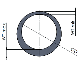
The formula for wall thinning due to bending is a complex equation that takes into account various factors such as the material properties, bending moment, and geometry of the pipe or tube. The general formula for wall thinning is given by the Barlow's formula, which states that the minimum wall thickness required to withstand a given internal pressure is proportional to the radius of the pipe and the internal pressure. However, when bending is involved, the formula becomes more complex and involves the bending moment, bending stress, and material properties.
Understanding the Basics of Wall Thinning
Wall thinning due to bending occurs when a pipe or tube is subjected to a bending moment, causing the wall to thin out on the outer side of the bend. This can lead to a reduction in the structural integrity of the pipe, making it more prone to failure. The key factors that influence wall thinning are the material properties, bending moment, and geometry of the pipe. Some of the important factors to consider are:
Factors Affecting Wall Thinning
Several factors can affect the wall thinning behavior of a pipe or tube, including corrosion, erosion, and mechanical damage. Corrosion can lead to a reduction in the wall thickness, making the pipe more susceptible to failure. Erosion can also cause wall thinning, particularly in areas where the fluid flow is high. Mechanical damage, such as dents and scratches, can also weaken the pipe and lead to wall thinning. Some of the key factors to consider are:
Consequences of Wall Thinning
The consequences of wall thinning can be severe, including pipe failure, leaks, and environmental damage. Pipe failure can occur when the wall thickness is reduced to a critical level, causing the pipe to rupture. Leaks can also occur when the wall thickness is reduced, allowing fluids to escape. Environmental damage can occur when hazardous materials are released into the environment due to pipe failure. Some of the key consequences to consider are:
Methods for Mitigating Wall Thinning
Several methods can be used to mitigate wall thinning, including regular inspections, maintenance, and repair. Regular inspections can help identify areas of wall thinning and allow for corrective action to be taken. Maintenance activities, such as cleaning and coating, can help reduce the risk of corrosion and erosion. Repair techniques, such as welding and cladding, can be used to restore the wall thickness and prevent failure. Some of the key methods to consider are:
Industrial Applications of Wall Thinning Formulas
The formulas for wall thinning due to bending have numerous industrial applications, including pipe design, plant operation, and safety assessment. Pipe design engineers use these formulas to determine the minimum wall thickness required for a given internal pressure and bending moment. Plant operators use these formulas to monitor the wall thickness of pipes and tubes and to identify areas of wall thinning. Safety assessors use these formulas to evaluate the risk of pipe failure and to develop mitigation strategies. Some of the key applications to consider are:
Frequently Asked Questions (FAQs)
What is the purpose of the Pipe Bends Minimum Wall Thickness Calculator per ASME B31.3?
The Pipe Bends Minimum Wall Thickness Calculator per ASME B31.3 is a tool designed to calculate the minimum wall thickness required for pipe bends in accordance with the ASME B31.3 standard. This standard, also known as the Chemical Plant and Petroleum Refinery Standard, provides guidelines for the design, construction, and inspection of piping systems in chemical plants and petroleum refineries. The calculator takes into account various parameters, such as the pipe material, pipe size, bend radius, and operating conditions, to determine the minimum wall thickness required to ensure the integrity and safety of the piping system. By using this calculator, engineers and designers can optimize their piping designs and ensure compliance with the ASME B31.3 standard.
How does the Pipe Bends Minimum Wall Thickness Calculator per ASME B31.3 account for different pipe materials and sizes?
The Pipe Bends Minimum Wall Thickness Calculator per ASME B31.3 accounts for different pipe materials and sizes by incorporating material properties and dimensional tolerances into its calculations. For example, the calculator considers the yield strength, tensile strength, and elastic modulus of the pipe material, as well as the pipe's outside diameter, wall thickness, and bend radius. The calculator also takes into account the manufacturing process and tolerances associated with different pipe sizes and materials. By considering these factors, the calculator can provide an accurate and reliable estimate of the minimum wall thickness required for a given pipe bend. This ensures that the piping system is designed to withstand the internal pressures, external loads, and environmental conditions to which it will be subjected, while also minimizing costs and optimizing system performance.
What are the key inputs and outputs of the Pipe Bends Minimum Wall Thickness Calculator per ASME B31.3?
The key inputs of the Pipe Bends Minimum Wall Thickness Calculator per ASME B31.3 include the pipe material, pipe size, bend radius, operating temperature, operating pressure, and corrosion allowance. The calculator also requires information about the piping system's design conditions, such as the design pressure, design temperature, and fluid properties. The key outputs of the calculator include the minimum wall thickness required for the pipe bend, as well as other important design parameters such as the maximum allowable working pressure and the maximum allowable stress. The calculator may also provide additional information, such as warnings or notices, to help engineers and designers identify potential design issues or hazards. By providing this information, the calculator enables users to optimize their piping designs and ensure compliance with the ASME B31.3 standard.
How can the Pipe Bends Minimum Wall Thickness Calculator per ASME B31.3 be used to optimize piping system design and ensure compliance with industry standards?
The Pipe Bends Minimum Wall Thickness Calculator per ASME B31.3 can be used to optimize piping system design and ensure compliance with industry standards by providing accurate and reliable estimates of the minimum wall thickness required for pipe bends. By using the calculator, engineers and designers can evaluate different design options and select the most cost-effective and efficient solution that meets the requirements of the ASME B31.3 standard. The calculator can also be used to identify potential design issues or hazards, such as insufficient wall thickness or excessive stress, and to develop mitigation strategies to address these issues. Additionally, the calculator can be used to document and record design decisions and calculations, providing a paper trail that can be used to demonstrate compliance with industry standards and regulations. By using the Pipe Bends Minimum Wall Thickness Calculator per ASME B31.3, engineers and designers can ensure that their piping systems are safe, reliable, and efficient, while also minimizing costs and optimizing system performance.
Deja una respuesta
Entradas Relacionadas