
Helical Gears Shafts Right Angles Approximate Design Equations and Calculator

Helical gears shafts with right angles are crucial components in mechanical engineering, providing efficient power transmission. Approximate design equations are essential for engineers to calculate and optimize gear performance. This article provides an in-depth look at the design equations and calculator for helical gears shafts at right angles, enabling accurate calculations and improved design outcomes. By utilizing these equations and calculator, engineers can ensure precise gear design, minimizing errors and enhancing overall system efficiency. The provided calculator simplifies the process, making it easier to achieve optimal results in gear design and development.
- Helical Gears Shafts Right Angles Approximate Design Equations and Calculator
- What is the formula for the helical gear angle?
- How to mesh helical gears?
- What is the formula for the module of a helical gear?
- What is the reference diameter of a helical gear?
-
Frequently Asked Questions (FAQs)
- What are Helical Gears and How Do They Differ from Other Types of Gears?
- What is the Purpose of Right Angle Gears and How Do They Relate to Helical Gears?
- What are Approximate Design Equations and How Are They Used in Helical Gear Design?
- What is a Helical Gear Shaft Calculator and How Can It Be Used to Design and Optimize Helical Gears?
Helical Gears Shafts Right Angles Approximate Design Equations and Calculator
The design of helical gears with shafts at right angles is a complex task that requires careful consideration of various parameters, including the gear ratio, pitch diameter, and pressure angle. To simplify the design process, engineers often use approximate design equations, which provide a good starting point for the design of helical gears. In this section, we will discuss the approximate design equations and calculator for helical gears with shafts at right angles.
Introduction to Helical Gears
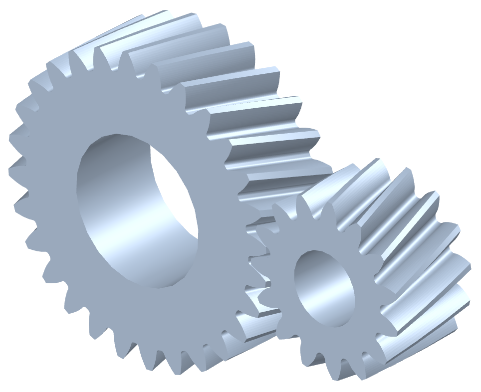
Helical gears are a type of gear that has teeth that are cut at an angle to the gear axis. This design allows for smoother operation and higher load-carrying capacity compared to spur gears. Helical gears are commonly used in applications where high torque and speed are required, such as in automotive transmissions and industrial gearboxes. The design of helical gears requires careful consideration of the gear ratio, pitch diameter, and pressure angle to ensure proper meshing and operation.
Approximate Design Equations
The approximate design equations for helical gears with shafts at right angles are based on the following parameters:
- Gear ratio (i)
- Pitch diameter (d)
- Pressure angle (α)
- Helix angle (β)
The equations can be used to calculate the required parameters, such as the pitch diameter and pressure angle, based on the desired gear ratio and helix angle. For example, the pitch diameter can be calculated using the equation: d = (i z2) / (z1 sin(α)), where z1 and z2 are the number of teeth on the pinion and gear, respectively.
Calculator for Helical Gears
A calculator for helical gears can be used to simplify the design process by providing a quick and easy way to calculate the required parameters. The calculator can be based on the approximate design equations and can take into account the gear ratio, pitch diameter, and pressure angle. The calculator can also provide a check for the interference between the teeth and the bending stress on the teeth.
Table of Design Parameters
The following table provides a summary of the design parameters for helical gears with shafts at right angles:
| Parameter | Symbol | Unit |
|---|---|---|
| Gear ratio | i | - |
| Pitch diameter | d | mm |
| Pressure angle | α | ° |
| Helix angle | β | ° |
Applications of Helical Gears
Helical gears have a wide range of applications, including:
- Automotive transmissions
- Industrial gearboxes
- Aerospace applications
- Robotics and automation
The advantages of helical gears, such as smooth operation and high load-carrying capacity, make them a popular choice for many industrial applications.
What is the formula for the helical gear angle?

The formula for the helical gear angle involves calculating the lead angle, which is the angle between the helix and the pitch circle. The formula is: tan(θ) = L / πd, where θ is the lead angle, L is the lead, and d is the pitch diameter. This formula is crucial in determining the helical gear angle, which affects the tooth profile and the overall performance of the gear system.
Understanding Helical Gear Angle Calculation
To calculate the helical gear angle, one must understand the geometry of the helical gear. The helix is the curved path that the teeth follow, and the lead is the distance that the helix advances along the axis. The calculation involves the following steps:
- Determine the lead and pitch diameter of the helical gear
- Calculate the lead angle using the formula tan(θ) = L / πd
- Use the lead angle to determine the helical gear angle, which is the angle between the helix and the pitch circle
Factors Affecting Helical Gear Angle
Several factors can affect the helical gear angle, including the tooth profile, pitch, and lead. The tooth profile can be either involute or cycloidal, and each has its own set of equations for calculating the helical gear angle. Additionally, the pitch and lead can be adjusted to achieve the desired helical gear angle.
- Tooth profile: The shape of the teeth can affect the helical gear angle
- Pitch: The distance between the teeth can affect the helical gear angle
- Lead: The distance that the helix advances along the axis can affect the helical gear angle
Importance of Helical Gear Angle in Gear Design
The helical gear angle plays a crucial role in gear design, as it affects the tooth profile, stress distribution, and overall performance of the gear system. A helical gear angle that is too shallow or too steep can lead to inefficiencies and premature wear.
- Tooth profile: The helical gear angle affects the shape of the teeth
- Stress distribution: The helical gear angle affects the distribution of stress on the teeth
- Efficiency: The helical gear angle affects the efficiency of the gear system
Helical Gear Angle and Tooth Profile
The helical gear angle is closely related to the tooth profile, as the helix is the curved path that the teeth follow. The tooth profile can be either involute or cycloidal, and each has its own set of equations for calculating the helical gear angle.
- Involute tooth profile: The teeth are shaped like a spiral
- Cycloidal tooth profile: The teeth are shaped like a cycloid
- Helical gear angle: The angle between the helix and the pitch circle
Applications of Helical Gear Angle in Industry
The helical gear angle has numerous applications in industry, including gearboxes, transmissions, and pumps. The helical gear angle can be adjusted to achieve the desired efficiency, torque, and speed.
- Gearboxes: The helical gear angle affects the efficiency and torque of the gearbox
- Transmissions: The helical gear angle affects the efficiency and speed of the transmission
- Pumps: The helical gear angle affects the flow rate and pressure of the pump
How to mesh helical gears?
Meshing helical gears requires careful consideration of several factors to ensure proper engagement and smooth operation. The process involves bringing the teeth of two gears into contact, allowing them to transmit torque and rotation while minimizing wear and vibration. To achieve this, the gears must be designed and manufactured with precise tolerances and specifications. The meshing process can be influenced by factors such as gear ratio, pitch, and pressure angle, which must be carefully balanced to optimize performance.
Understanding Helical Gear Design
Helical gear design is critical to the meshing process. The helix angle and tooth profile must be carefully designed to ensure proper engagement and minimize interference. The design should also take into account the material properties and manufacturing process to ensure that the gears can withstand the stresses and loads imposed on them. Some key considerations in helical gear design include:
- Tooth thickness: The thickness of the teeth must be carefully calculated to ensure proper engagement and minimize wear.
- Helix angle: The helix angle must be designed to provide a smooth and efficient transfer of torque and rotation.
- Pitch: The pitch of the gears must be carefully matched to ensure proper meshing and minimize vibration.
Meshing Helical Gears with Different Helix Angles
Meshing helical gears with different helix angles requires careful consideration of the gear ratio and tooth profile. The helix angle of the two gears must be compatible to ensure proper engagement and minimize wear and vibration. The design should also take into account the material properties and manufacturing process to ensure that the gears can withstand the stresses and loads imposed on them. Some key considerations when meshing helical gears with different helix angles include:
- Helix angle compatibility: The helix angles of the two gears must be compatible to ensure proper engagement and minimize wear.
- Tooth profile modification: The tooth profile may need to be modified to ensure proper engagement and minimize interference.
- Gear ratio adjustment: The gear ratio may need to be adjusted to ensure proper meshing and minimize vibration.
Effects of Pitch and Pressure Angle on Meshing
The pitch and pressure angle of the gears can significantly affect the meshing process. The pitch must be carefully matched to ensure proper meshing and minimize vibration, while the pressure angle must be designed to provide a smooth and efficient transfer of torque and rotation. Some key considerations when evaluating the effects of pitch and pressure angle on meshing include:
- Pitch matching: The pitch of the two gears must be carefully matched to ensure proper meshing and minimize vibration.
- Pressure angle optimization: The pressure angle must be optimized to provide a smooth and efficient transfer of torque and rotation.
- Tooth profile design: The tooth profile must be designed to ensure proper engagement and minimize wear.
Minimizing Wear and Vibration in Helical Gear Meshing
Minimizing wear and vibration is critical to ensuring the reliable operation of helical gear meshes. This can be achieved by optimizing the gear design, manufacturing process, and operating conditions. Some key considerations when minimizing wear and vibration include:
- Gear material selection: The gear material must be carefully selected to minimize wear and ensure reliable operation.
- Surface finish optimization: The surface finish of the gears must be optimized to minimize wear and vibration.
- Lubrication and maintenance: The gears must be properly lubricated and maintained to minimize wear and ensure reliable operation.
Advanced Techniques for Helical Gear Meshing
Advanced techniques such as finite element analysis and computer-aided design can be used to optimize the meshing of helical gears. These techniques allow for the simulation and analysis of the stress and strain on the gears, enabling the optimization of the gear design and manufacturing process. Some key considerations when using advanced techniques for helical gear meshing include:
- Finite element analysis: Finite element analysis can be used to simulate and analyze the stress and strain on the gears.
- Computer-aided design: Computer-aided design can be used to optimize the gear design and manufacturing process.
- Experimental validation: The results of the analysis and simulation must be validated through experimental testing to ensure reliable operation.
What is the formula for the module of a helical gear?

The formula for the module of a helical gear is given by: m = p / π, where m is the module, p is the pitch, and π is a mathematical constant approximately equal to 3.14159. This formula is used to calculate the size of the teeth of a helical gear, which is essential for ensuring proper meshing and transmission of rotational motion.
Understanding the Module of a Helical Gear
The module of a helical gear is a critical parameter that determines the size and shape of the teeth. A smaller module results in smaller teeth, while a larger module results in larger teeth. The module is also related to the pitch of the gear, which is the distance between adjacent teeth. The formula for the module takes into account the pitch and the mathematical constant π to provide an accurate calculation of the tooth size. Some key points to consider when calculating the module include:
- The pitch of the gear is measured in units of length, such as millimeters or inches.
- The mathematical constant π is essential for converting the pitch to the module.
- A larger module results in a stronger gear, but may also increase the weight and cost of the gear.
Calculating the Pitch of a Helical Gear
The pitch of a helical gear is calculated using the formula: p = π m, where p is the pitch, π is the mathematical constant, and m is the module. This formula is used to determine the distance between adjacent teeth, which is critical for ensuring proper meshing and transmission of rotational motion. Some key points to consider when calculating the pitch include:
- The module is a critical parameter that determines the size and shape of the teeth.
- The mathematical constant π is essential for converting the module to the pitch.
- A smaller pitch results in a finer tooth pitch, which may be desirable for high-precision applications.
Factors Affecting the Module of a Helical Gear
Several factors can affect the module of a helical gear, including the material used to manufacture the gear, the design of the gear, and the application in which the gear will be used. For example, a gear made from a strong and durable material may be able to withstand a larger module, while a gear made from a weak and brittle material may require a smaller module. Some key points to consider when selecting a module include:
- The strength and durability of the gear material.
- The design of the gear, including the number of teeth and the tooth shape.
- The application in which the gear will be used, including the speed, torque, and environmental conditions.
Design Considerations for Helical Gears
When designing a helical gear, several parameters must be considered, including the module, pitch, and number of teeth. The module is critical for determining the size and shape of the teeth, while the pitch is essential for ensuring proper meshing and transmission of rotational motion. The number of teeth can also affect the strength and durability of the gear. Some key points to consider when designing a helical gear include:
- The module and pitch of the gear.
- The number of teeth and the tooth shape.
- The material used to manufacture the gear and its mechanical properties.
Applications of Helical Gears
Helical gears are used in a wide range of applications, including industrial machinery, automotive systems, and aerospace engineering. They are often used to transmit rotational motion and to change the speed and torque of a system. The module and pitch of a helical gear can be critical for ensuring proper meshing and transmission of rotational motion in these applications. Some key points to consider when using helical gears in applications include:
- The speed and torque requirements of the application.
- The environmental conditions in which the gear will be used, including temperature, humidity, and vibration.
- The reliability and maintenance requirements of the application.
What is the reference diameter of a helical gear?
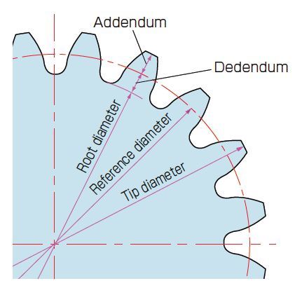
The reference diameter of a helical gear is the diameter of the pitch circle, which is the circle that passes through the teeth of the gear at the point where they mesh with the teeth of another gear. This diameter is used as a reference point for calculating the gear ratio and other important parameters of the gear.
Definition of Reference Diameter
The reference diameter is an important concept in gear design, as it is used to determine the tooth profile and the contact ratio of the gear. The reference diameter is typically defined as the diameter of the pitch circle, which is the circle that passes through the teeth of the gear at the point where they mesh with the teeth of another gear. The key factors that determine the reference diameter are:
- The number of teeth on the gear
- The module or pitch of the gear
- The helix angle of the gear
Calculation of Reference Diameter
To calculate the reference diameter of a helical gear, you need to know the number of teeth, the module or pitch, and the helix angle. The reference diameter can be calculated using the following formula: reference diameter = (number of teeth x module) / (cos(helix angle)). The key steps in calculating the reference diameter are:
- Determine the number of teeth on the gear
- Determine the module or pitch of the gear
- Determine the helix angle of the gear
Importance of Reference Diameter
The reference diameter is a critical parameter in gear design, as it affects the gear ratio, the tooth profile, and the contact ratio. A correct reference diameter ensures that the gear will mesh properly with other gears, and that the gearbox will operate smoothly and efficiently. The key benefits of a correct reference diameter are:
- Improved gear ratio and torque transmission
- Increased gear life and reliability
- Reduced noise and vibration
Factors Affecting Reference Diameter
The reference diameter of a helical gear can be affected by several factors, including the number of teeth, the module or pitch, and the helix angle. Other factors that can affect the reference diameter include the material of the gear, the manufacturing process, and the operating conditions. The key factors that affect the reference diameter are:
- The gear material and its properties
- The manufacturing process and its tolerances
- The operating conditions, including temperature and load
Applications of Reference Diameter
The reference diameter is an important concept in gear design and has many practical applications. It is used to design and manufacture gears for a wide range of applications, including automotive, aerospace, and industrial. The key applications of the reference diameter are:
- Gearbox design and manufacture
- Transmission design and optimization
- Mechanical system design and analysis
Frequently Asked Questions (FAQs)
What are Helical Gears and How Do They Differ from Other Types of Gears?
Helical gears are a type of gear that has teeth that are cut at an angle to the axis of the gear. This design allows for smooth and quiet operation, as well as increased torque and efficiency. Helical gears differ from other types of gears, such as spur gears and bevel gears, in that they have a helical shape, which means that the teeth are cut at an angle to the axis of the gear. This design allows helical gears to be used in a variety of applications, including transmissions, gearboxes, and pumps. The helical shape of the teeth also allows for flexibility in the design of the gear, as the angle of the teeth can be adjusted to suit the specific needs of the application. Overall, helical gears are a versatile and efficient type of gear that can be used in a wide range of applications.
What is the Purpose of Right Angle Gears and How Do They Relate to Helical Gears?
Right angle gears, also known as bevel gears, are used to change the direction of rotation by 90 degrees. They are commonly used in applications where space is limited, such as in robotics and aerospace. Right angle gears can be used in conjunction with helical gears to create a compact and efficient gearbox. The right angle design allows for the input and output shafts to be at a 90-degree angle, which can be useful in applications where space is limited. Helical gears can be used as the input or output gear in a right angle gearbox, allowing for smooth and quiet operation. The combination of helical gears and right angle gears can provide a highly efficient and compact solution for a wide range of applications.
What are Approximate Design Equations and How Are They Used in Helical Gear Design?
Approximate design equations are mathematical formulas that are used to estimate the design parameters of a helical gear. These equations can be used to calculate the tooth width, pitch diameter, and pressure angle of the gear, among other parameters. The approximate nature of these equations means that they are not exact, but rather provide a close estimate of the design parameters. This can be useful in the initial stages of the design process, where a quick and rough estimate of the design parameters is needed. The approximate design equations can be used to iterate on the design, making adjustments as needed until the final design is optimized. The use of computer-aided design (CAD) software can also help to refine the design and provide a more accurate estimate of the design parameters.
What is a Helical Gear Shaft Calculator and How Can It Be Used to Design and Optimize Helical Gears?
A helical gear shaft calculator is a tool that can be used to design and optimize helical gears. This calculator can be used to input the design parameters of the gear, such as the tooth width, pitch diameter, and pressure angle, and then calculate the resulting design parameters, such as the torque and efficiency of the gear. The calculator can also be used to iterate on the design, making adjustments as needed until the final design is optimized. The use of a helical gear shaft calculator can help to save time and reduce errors in the design process, as well as provide a more accurate estimate of the design parameters. The calculator can also be used to compare different design options and select the best design for a given application. Overall, a helical gear shaft calculator is a valuable tool for anyone involved in the design and optimization of helical gears.
Deja una respuesta
Entradas Relacionadas