
Head Changes Pipe Size Reduction Formula and Calculator

The head change in a piping system is crucial in determining the pressure drop and flow rate. Reducing pipe size can significantly impact these factors, and calculating the head change is essential for efficient system design. The Formula for head change due to pipe size reduction is complex, taking into account factors such as flow rate, pipe diameter, and fluid properties. This article provides a comprehensive guide to the Head Change Pipe Size Reduction Formula and includes a calculator to simplify the process, ensuring accurate calculations and optimal system performance. Accurate calculations are vital for system efficiency.
-
Understanding Head Changes Pipe Size Reduction Formula and Calculator
- Introduction to Head Changes Pipe Size Reduction Formula
- Calculator for Head Changes Pipe Size Reduction
- Applications of Head Changes Pipe Size Reduction Formula and Calculator
- Limitations and Assumptions of Head Changes Pipe Size Reduction Formula
- Future Developments in Head Changes Pipe Size Reduction Formula and Calculator
- What is the formula for pipe size calculation?
- Which formula is used to calculate head loss in valves?
- What is the Hazen Williams formula for pipe flow?
- What is the relationship between pipe diameter and head loss?
-
Frequently Asked Questions (FAQs)
- What is the Head Changes Pipe Size Reduction Formula and how is it used in fluid dynamics?
- How does the Head Changes Pipe Size Reduction Calculator work and what are its limitations?
- What are the key factors that affect the head changes pipe size reduction formula and how do they impact the calculation?
- How can the head changes pipe size reduction formula be applied in real-world engineering applications, such as pipeline design and optimization?
Understanding Head Changes Pipe Size Reduction Formula and Calculator
The Head Changes Pipe Size Reduction Formula and Calculator is a crucial tool in the field of fluid dynamics and pipe flow. It is used to calculate the reduction in pipe size that occurs when there is a change in the head or pressure of a fluid flowing through a pipe. This formula and calculator are essential in various industries such as petroleum, chemical, and power generation, where the transportation of fluids through pipes is a critical process.
Introduction to Head Changes Pipe Size Reduction Formula
The Head Changes Pipe Size Reduction Formula is based on the Bernoulli's principle, which states that the sum of the pressure and the kinetic energy of a fluid remains constant along a streamline. The formula takes into account the initial head, final head, initial pipe size, and final pipe size to calculate the reduction in pipe size. This formula is widely used in the design and operation of pipelines, pumps, and turbines.
Calculator for Head Changes Pipe Size Reduction
The calculator for Head Changes Pipe Size Reduction is a computer-based tool that uses the formula to calculate the reduction in pipe size. It takes into account various input parameters such as the fluid properties, pipe material, and flow rate. The calculator provides a quick and accurate way to determine the reduction in pipe size, which is essential in the design and operation of fluid transportation systems.
Applications of Head Changes Pipe Size Reduction Formula and Calculator
The Head Changes Pipe Size Reduction Formula and Calculator have various applications in different industries. Some of the key applications include:
| Industry | Application |
|---|---|
| Petroleum | Pipeline design and operation |
| Chemical | Process pipe sizing and design |
| Power Generation | Turbine design and operation |
These applications highlight the importance of the Head Changes Pipe Size Reduction Formula and Calculator in ensuring the efficient and safe transportation of fluids.
Limitations and Assumptions of Head Changes Pipe Size Reduction Formula
The Head Changes Pipe Size Reduction Formula and Calculator are based on certain assumptions and have limitations. Some of the key limitations and assumptions include:
Constant fluid properties
Laminar flow
Negligible pipe friction
These assumptions and limitations must be considered when using the formula and calculator to ensure accurate and reliable results.
Future Developments in Head Changes Pipe Size Reduction Formula and Calculator
The Head Changes Pipe Size Reduction Formula and Calculator are continuously being improved and updated to reflect the latest research and technological advancements. Some of the future developments include:
Incorporation of turbulent flow models
Development of more accurate pipe friction models
Integration with computational fluid dynamics (CFD) tools
These developments will further enhance the accuracy and reliability of the Head Changes Pipe Size Reduction Formula and Calculator, making them even more essential tools in the field of fluid dynamics and pipe flow.
What is the formula for pipe size calculation?
The formula for pipe size calculation is a complex process that involves several variables, including the flow rate, fluid properties, and pipe characteristics. The most commonly used formula for pipe size calculation is the Hazen-Williams equation, which is a semi-empirical equation that relates the flow rate and head loss in a pipe. The equation is as follows: Q = 1.318 C D^2.63 (h/L)^0.54, where Q is the flow rate, C is the Hazen-Williams coefficient, D is the pipe diameter, h is the head loss, and L is the pipe length.
Understanding the Hazen-Williams Equation
The Hazen-Williams equation is a widely used formula for pipe size calculation, and it is based on the principles of fluid dynamics. To use this equation, you need to know the flow rate, fluid properties, and pipe characteristics. The equation is sensitive to the Hazen-Williams coefficient, which is a dimensionless value that depends on the pipe material and condition. Here are some key points to consider when using the Hazen-Williams equation:
- The Hazen-Williams coefficient is a critical parameter in the equation, and it can range from 80 to 150, depending on the pipe material and condition.
- The flow rate is the volumetric flow rate of the fluid, and it is typically measured in cubic feet per second or gallons per minute.
- The pipe diameter is the inside diameter of the pipe, and it is typically measured in inches or millimeters.
Calculating the Head Loss
The head loss is an important parameter in the Hazen-Williams equation, and it is calculated using the Darcy-Weisbach equation. The head loss is the energy loss per unit weight of fluid, and it is typically measured in feet or meters. To calculate the head loss, you need to know the flow rate, fluid properties, and pipe characteristics. Here are some key points to consider when calculating the head loss:
- The Darcy-Weisbach equation is a semi-empirical equation that relates the head loss and flow rate in a pipe.
- The friction factor is a critical parameter in the Darcy-Weisbach equation, and it depends on the pipe material and condition.
- The pipe roughness is an important factor in calculating the head loss, and it is typically measured in inches or millimeters.
Choosing the Right Pipe Size
Choosing the right pipe size is a critical decision in piping system design, and it depends on several factors, including the flow rate, fluid properties, and pipe characteristics. The pipe size should be large enough to minimize the head loss and energy loss, but small enough to minimize the cost and space requirements. Here are some key points to consider when choosing the right pipe size:
- The pipe size should be selected based on the maximum flow rate and minimum head loss.
- The pipe material and condition should be considered when selecting the pipe size.
- The pipe size should be verified using pipe sizing charts or calculations to ensure that it meets the required specifications.
Using Pipe Sizing Charts
Pipe sizing charts are useful tools for selecting the right pipe size, and they are based on the Hazen-Williams equation and Darcy-Weisbach equation. The charts provide a quick and easy way to determine the pipe size based on the flow rate, fluid properties, and pipe characteristics. Here are some key points to consider when using pipe sizing charts:
- The pipe sizing charts should be selected based on the pipe material and condition.
- The charts should be used in conjunction with calculations to verify the pipe size.
- The charts are simplified versions of the Hazen-Williams equation and Darcy-Weisbach equation, and they may not provide exact solutions.
Common Errors in Pipe Size Calculation
Common errors in pipe size calculation can lead to inefficient piping systems, energy losses, and costly repairs. The errors can occur due to inaccurate assumptions, insufficient data, or incorrect calculations. Here are some key points to consider to avoid common errors in pipe size calculation:
- The flow rate and fluid properties should be accurately measured or estimated.
- The pipe characteristics and material properties should be well understood.
- The calculations should be carefully performed and verified using multiple methods.
Which formula is used to calculate head loss in valves?
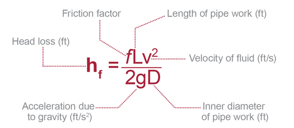
The formula used to calculate head loss in valves is the Darcy-Weisbach equation, which is given by: h = (f L v^2) / (2 g D), where h is the head loss, f is the friction factor, L is the length of the valve, v is the velocity of the fluid, g is the acceleration due to gravity, and D is the diameter of the valve.
Introduction to Head Loss in Valves
Head loss in valves is a critical parameter in the design and operation of fluid systems. The head loss in a valve is the pressure drop that occurs as fluid flows through the valve. This pressure drop is caused by the resistance to flow, which is created by the valve's geometry and the velocity of the fluid. The Darcy-Weisbach equation is commonly used to calculate the head loss in valves, taking into account the friction factor, length, velocity, gravity, and diameter of the valve.
- The Darcy-Weisbach equation is a widely accepted formula for calculating head loss in valves.
- The friction factor is a critical component of the equation, as it represents the resistance to flow in the valve.
- The velocity of the fluid is also an important factor, as it affects the pressure drop and head loss in the valve.
Types of Head Loss in Valves
There are several types of head loss that can occur in valves, including frictional head loss, minor head loss, and major head loss. Frictional head loss occurs due to the friction between the fluid and the valve's surface, while minor head loss occurs due to the turbulence and separation of the fluid as it flows through the valve. Major head loss occurs due to the restriction of the valve and the velocity of the fluid.
- Frictional head loss is the most common type of head loss in valves.
- Minor head loss can be significant in valves with complex geometries.
- Major head loss can occur in valves with high velocity and restriction.
Factors Affecting Head Loss in Valves
Several factors can affect the head loss in valves, including the valve type, size, material, and operating conditions. The valve type can affect the friction factor and the geometry of the valve, while the size and material can affect the surface roughness and the velocity of the fluid. The operating conditions, such as the pressure and temperature, can also affect the head loss in the valve.
- The valve type can significantly affect the head loss in the valve.
- The size and material of the valve can also impact the head loss.
- The operating conditions must be carefully considered when calculating head loss.
Calculation of Head Loss in Valves
The calculation of head loss in valves involves using the Darcy-Weisbach equation and considering the friction factor, length, velocity, gravity, and diameter of the valve. The friction factor can be determined using the Colebrook-White equation or other empirical formulas, while the length and diameter of the valve can be measured or obtained from the valve's specifications.
- The Darcy-Weisbach equation is a widely accepted formula for calculating head loss.
- The friction factor must be carefully determined to ensure accurate calculations.
- The length and diameter of the valve are critical parameters in the calculation.
Application of Head Loss in Valves
The calculation of head loss in valves has several practical applications, including the design and operation of fluid systems, such as pipelines, pumping systems, and water treatment plants. The head loss in valves can affect the performance and efficiency of these systems, and must be carefully considered to ensure optimal operation.
- The head loss in valves has significant implications for the design of fluid systems.
- The performance and efficiency of fluid systems can be affected by head loss.
- Accurate calculations of head loss are essential for optimal system operation.
What is the Hazen Williams formula for pipe flow?

The Hazen Williams formula is an empirical equation that is used to calculate the head loss in a pipe flow. The formula is given by: h_f = (10.67 L (V/C)^1.85) / (d^1.17), where h_f is the head loss, L is the length of the pipe, V is the velocity of the fluid, C is the Hazen Williams coefficient, and d is the diameter of the pipe.
What is the Hazen Williams Coefficient?
The Hazen Williams coefficient is a measure of the roughness of the pipe. It is a dimensionless value that ranges from 100 to 150, with higher values indicating a smoother pipe. The coefficient is typically determined through experimentation or by using tables or charts that provide values for different types of pipes. Some common values of the Hazen Williams coefficient include:
- 100 for very rough pipes, such as those made of concrete or stone
- 120 for rough pipes, such as those made of cast iron or steel
- 140 for smooth pipes, such as those made of copper or PVC
How to Apply the Hazen Williams Formula
The Hazen Williams formula can be applied to a variety of pipe flow situations, including water distribution systems, sewer systems, and industrial processes. To apply the formula, you need to know the length and diameter of the pipe, as well as the velocity of the fluid and the Hazen Williams coefficient. The formula can be used to calculate the head loss in the pipe, which is useful for determining the required pump head or pressure drop.
- First, determine the length and diameter of the pipe
- Next, determine the velocity of the fluid and the Hazen Williams coefficient
- Then, plug these values into the Hazen Williams formula to calculate the head loss
Limitations of the Hazen Williams Formula
The Hazen Williams formula has several limitations, including the fact that it is an empirical equation that is only valid for certain ranges of Reynolds numbers and pipe roughness. Additionally, the formula does not account for turbulence or non-uniform flow, which can occur in real-world pipe flow situations. Therefore, the formula should be used with caution and only for simplified analyses.
- The formula is only valid for laminar flow or turbulent flow with a low Reynolds number
- The formula does not account for non-uniform flow or turbulence
- The formula should be used with caution and only for simplified analyses
Comparison to Other Pipe Flow Formulas
The Hazen Williams formula is one of several pipe flow formulas that can be used to calculate the head loss in a pipe. Other formulas, such as the Darcy-Weisbach equation and the Manning equation, may be more accurate or applicable to certain situations. The choice of formula depends on the specific requirements of the analysis and the available data.
- The Darcy-Weisbach equation is a more general equation that can be used for a wider range of Reynolds numbers
- The Manning equation is a simplified equation that is commonly used for open-channel flow
- The choice of formula depends on the specific requirements of the analysis and the available data
Applications of the Hazen Williams Formula
The Hazen Williams formula has a variety of applications in civil engineering, mechanical engineering, and environmental engineering. The formula can be used to design water distribution systems, sewer systems, and industrial processes, as well as to analyze existing systems and determine the required pump head or pressure drop. Some common applications of the formula include:
- Designing water distribution systems to ensure adequate pressure and flow rates
- Analyzing sewer systems to determine the required pump head and pressure drop
- Determining the required pump head and pressure drop for industrial processes
What is the relationship between pipe diameter and head loss?
The relationship between pipe diameter and head loss is a crucial aspect of fluid dynamics, particularly in the context of pipe flow. As the diameter of a pipe increases, the head loss decreases, and vice versa. This is because a larger pipe diameter results in a smaller friction factor, which in turn reduces the energy loss due to friction. In contrast, a smaller pipe diameter leads to a higher friction factor, resulting in greater energy loss and increased head loss.
Pipe Diameter and Flow Rate
The relationship between pipe diameter and head loss is also influenced by the flow rate. As the flow rate increases, the head loss increases, regardless of the pipe diameter. However, a larger pipe diameter can accommodate higher flow rates with less head loss. The key factors to consider are:
- The Reynolds number, which determines the nature of the flow (laminar or turbulent) and affects the head loss
- The pipe roughness, which can increase or decrease the head loss depending on the flow rate and pipe diameter
- The fluid properties, such as density and viscosity, which influence the head loss and flow rate
Head Loss and Friction Factor
The friction factor is a critical component in determining the head loss in a pipe. The friction factor is a function of the Reynolds number and the pipe roughness. As the friction factor increases, the head loss also increases. A larger pipe diameter results in a smaller friction factor, which reduces the head loss. The key factors to consider are:
- The Darcy-Weisbach equation, which relates the head loss to the friction factor and pipe diameter
- The Colebrook-White equation, which is used to calculate the friction factor for turbulent flow
- The Moody chart, which provides a graphical representation of the friction factor and head loss for different pipe diameters and flow rates
Pipe Material and Head Loss
The pipe material can also affect the head loss, particularly in terms of pipe roughness. Different materials have varying levels of roughness, which can increase or decrease the head loss. For example, copper pipes are generally smoother than steel pipes, resulting in less head loss. Conversely, concrete pipes can be very rough, leading to increased head loss. The key factors to consider are:
- The pipe material's roughness coefficient, which affects the friction factor and head loss
- The pipe's surface finish, which can impact the head loss and flow rate
- The pipe's age and condition, which can lead to changes in the pipe's roughness and head loss over time
Flow Regime and Head Loss
The flow regime, whether laminar or turbulent, plays a significant role in determining the head loss. Laminar flow results in less head loss than turbulent flow, particularly in smaller pipe diameters. As the flow rate increases, the flow regime can change from laminar to turbulent, leading to increased head loss. The key factors to consider are:
- The Reynolds number, which determines the flow regime and affects the head loss
- The pipe diameter, which influences the flow regime and head loss
- The fluid properties, such as density and viscosity, which impact the flow regime and head loss
Energy Loss and Head Loss
The energy loss due to friction is a critical component of head loss. As the fluid flows through the pipe, energy is lost due to friction, which results in a decrease in pressure and velocity. The key factors to consider are:
- The energy loss coefficient, which relates the energy loss to the head loss
- The pipe diameter, which affects the energy loss and head loss
- The flow rate, which influences the energy loss and head loss
The relationship between pipe diameter and head loss is complex and influenced by various factors, including flow rate, pipe roughness, fluid properties, and flow regime. Understanding these factors is essential for designing and optimizing pipe systems to minimize head loss and energy loss. Pipe diameter and head loss are critical parameters in fluid dynamics, and their relationship must be carefully considered to achieve efficient and effective pipe system design.
Frequently Asked Questions (FAQs)
What is the Head Changes Pipe Size Reduction Formula and how is it used in fluid dynamics?
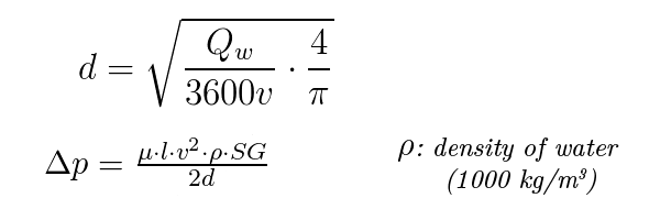
The Head Changes Pipe Size Reduction Formula is a mathematical equation used to calculate the head loss that occurs when a fluid flows through a pipe with a reduced diameter. This formula is essential in fluid dynamics as it helps engineers design and optimize pipework systems, ensuring that the flow of fluids is efficient and effective. The formula takes into account the velocity of the fluid, the diameter of the pipe, and the density of the fluid, allowing engineers to predict the pressure drop that will occur as the fluid flows through the pipe. By using this formula, engineers can optimize the design of pipework systems, reducing energy losses and ensuring that the system operates at maximum efficiency.
How does the Head Changes Pipe Size Reduction Calculator work and what are its limitations?
The Head Changes Pipe Size Reduction Calculator is a software tool that uses the Head Changes Pipe Size Reduction Formula to calculate the head loss that occurs when a fluid flows through a pipe with a reduced diameter. The calculator takes into account various input parameters, such as the flow rate, pipe diameter, and fluid properties, and uses these parameters to calculate the head loss and pressure drop. However, the calculator has several limitations, including the assumption of a steady-state flow and the neglect of frictional losses. Additionally, the calculator is only applicable to incompressible fluids and may not be suitable for compressible fluids or two-phase flows. Despite these limitations, the calculator is a valuable tool for engineers, allowing them to quickly and easily calculate the head loss and pressure drop in pipework systems.
What are the key factors that affect the head changes pipe size reduction formula and how do they impact the calculation?
The key factors that affect the head changes pipe size reduction formula are the velocity of the fluid, the diameter of the pipe, and the density of the fluid. The velocity of the fluid is a critical factor, as it directly affects the head loss and pressure drop. The diameter of the pipe also plays a significant role, as a smaller diameter pipe will result in a greater head loss and pressure drop. The density of the fluid is also important, as it affects the momentum of the fluid and the resulting head loss. Other factors, such as pipe roughness and fluid viscosity, can also impact the calculation, although to a lesser extent. By understanding how these factors affect the formula, engineers can optimize the design of pipework systems and ensure that they operate at maximum efficiency.
How can the head changes pipe size reduction formula be applied in real-world engineering applications, such as pipeline design and optimization?
The head changes pipe size reduction formula can be applied in a variety of real-world engineering applications, including pipeline design and optimization. By using the formula, engineers can predict the head loss and pressure drop that will occur in a pipeline, allowing them to design the pipeline to minimize energy losses and maximize efficiency. The formula can also be used to optimize the design of pipework systems, such as pumping systems and turbine systems, by ensuring that the flow rate and pressure are optimized for the specific application. Additionally, the formula can be used to troubleshoot problems in existing pipework systems, such as pressure drops and flow rate reductions, by identifying the source of the problem and recommending solutions. By applying the head changes pipe size reduction formula, engineers can improve the efficiency and reliability of pipework systems, reducing energy losses and operating costs.
Deja una respuesta
Entradas Relacionadas