
Gear Tooth Strength Lewis Equation Calculator

The Gear Tooth Strength Lewis Equation Calculator is a crucial tool in mechanical engineering, specifically in the design and analysis of gear systems. This calculator utilizes the Lewis equation, a widely accepted method for determining the strength of gear teeth. By inputting key parameters such as the tooth width, pitch, and material properties, engineers can quickly calculate the maximum allowable stress and bending strength of gear teeth, ensuring the reliability and efficiency of the gear system. This calculator is essential for optimizing gear design and preventing potential failures. Accurate calculations are vital for safe operation.
- Gear Tooth Strength Lewis Equation Calculator: A Comprehensive Guide
- What is the Lewis equation for the strength of a gear tooth?
- What Lewis equation is used to obtain the strength of bevel gears?
- What is the Buckingham equation for gear teeth?
- How to calculate gear tooth strength?
-
Frequently Asked Questions (FAQs)
- What is the Gear Tooth Strength Lewis Equation Calculator and how does it work?
- What are the key factors that affect the calculation of gear tooth strength using the Lewis equation?
- How does the Gear Tooth Strength Lewis Equation Calculator account for different materials and their properties?
- What are the limitations and potential sources of error when using the Gear Tooth Strength Lewis Equation Calculator?
Gear Tooth Strength Lewis Equation Calculator: A Comprehensive Guide
The Gear Tooth Strength Lewis Equation Calculator is a mathematical tool used to calculate the strength of gear teeth, which is essential in designing and manufacturing gears for various industrial applications. The calculator is based on the Lewis equation, a widely accepted formula for determining the bending stress and compressive stress of gear teeth.
Introduction to Gear Tooth Strength
Gear tooth strength is a critical factor in determining the reliability and performance of gears in various industrial applications. The strength of gear teeth depends on several factors, including the material used, tooth geometry, and loading conditions. The Gear Tooth Strength Lewis Equation Calculator takes into account these factors to provide an accurate calculation of gear tooth strength.
Lewis Equation and its Significance
The Lewis equation is a mathematical formula developed by Wilfred Lewis in the early 20th century to calculate the bending stress of gear teeth. The equation is based on the beam theory and takes into account the tooth width, tooth height, and loading conditions. The Lewis equation is widely accepted and used in the industry due to its simplicity and accuracy.
Factors Affecting Gear Tooth Strength
Several factors affect gear tooth strength, including:
| Factor | Description |
|---|---|
| Material | The type of material used to manufacture the gear, such as steel or aluminum. |
| Tooth Geometry | The shape and size of the gear teeth, including the tooth width and tooth height. |
| Loading Conditions | The type and magnitude of loading applied to the gear, including tangential force and radial force. |
Gear Tooth Strength Calculation using Lewis Equation
The Gear Tooth Strength Lewis Equation Calculator uses the Lewis equation to calculate the bending stress and compressive stress of gear teeth. The calculation involves inputting the relevant parameters, such as tooth geometry, material properties, and loading conditions, into the calculator. The calculator then provides the calculated values of bending stress and compressive stress, which can be used to determine the factor of safety and gear tooth strength.
Applications of Gear Tooth Strength Lewis Equation Calculator
The Gear Tooth Strength Lewis Equation Calculator has various applications in industries that use gears and gearboxes, including:
Aerospace: Designing and manufacturing gears for aircraft and spacecraft applications.
Automotive: Designing and manufacturing gears for vehicle transmissions and drivetrains.
Industrial: Designing and manufacturing gears for industrial machinery and equipment.
The calculator is a useful tool for engineers and designers to ensure that gears are designed and manufactured to withstand the stresses and loads applied to them, thereby ensuring reliability and performance.
What is the Lewis equation for the strength of a gear tooth?
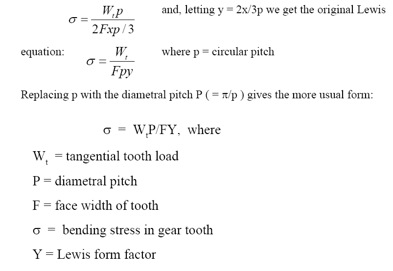
The Lewis equation is a formula used to calculate the strength of a gear tooth, taking into account the bending stress and contact stress that the tooth is subjected to. The equation is named after Wilfred Lewis, who first proposed it in the early 20th century. The Lewis equation is widely used in the design and analysis of gear systems, and is considered a fundamental tool for ensuring the reliability and performance of gear-based machinery.
Introduction to the Lewis Equation
The Lewis equation is based on the principle that the strength of a gear tooth is determined by its ability to resist bending and contact stresses. The equation takes into account factors such as the tooth width, tooth thickness, pitch circle diameter, and transverse module. To apply the Lewis equation, the following steps are necessary:
- Determine the bending stress and contact stress that the gear tooth is subjected to
- Calculate the tooth width and tooth thickness using the pitch circle diameter and transverse module
- Apply the Lewis equation to determine the strength of the gear tooth
Key Factors in the Lewis Equation
The Lewis equation involves several key factors that affect the strength of a gear tooth. These include the tooth width, tooth thickness, pitch circle diameter, and transverse module. The equation also takes into account the bending stress and contact stress that the tooth is subjected to, as well as the material properties of the gear. The following are some of the key factors:
- Tooth width: The width of the gear tooth, which affects its ability to resist bending and contact stresses
- Tooth thickness: The thickness of the gear tooth, which affects its ability to resist bending and contact stresses
- Pitch circle diameter: The diameter of the circle that passes through the centers of the gear teeth, which affects the tooth width and tooth thickness
Assumptions and Limitations of the Lewis Equation
The Lewis equation is based on several assumptions and limitations, including the assumption that the gear tooth is symmetric and that the bending stress and contact stress are uniformly distributed. The equation also assumes that the material properties of the gear are isotropic and homogeneous. The following are some of the assumptions and limitations:
- The gear tooth is symmetric and has a constant width and thickness
- The bending stress and contact stress are uniformly distributed across the gear tooth
- The material properties of the gear are isotropic and homogeneous
Applications of the Lewis Equation
The Lewis equation has a wide range of applications in the design and analysis of gear systems. It is used to determine the strength and reliability of gear teeth, and to optimize the design of gear systems for performance and efficiency. The equation is also used to analyze the failure of gear teeth and to identify the causes of wear and fatigue. The following are some of the applications:
- Determining the strength and reliability of gear teeth
- Optimizing the design of gear systems for performance and efficiency
- Analyzing the failure of gear teeth and identifying the causes of wear and fatigue
Comparison with Other Gear Tooth Strength Equations
The Lewis equation is one of several equations that are used to calculate the strength of gear teeth. Other equations, such as the AGMA and DIN equations, also take into account the bending stress and contact stress that the tooth is subjected to. The following are some of the differences between the Lewis equation and other gear tooth strength equations:
- The AGMA equation uses a different formula to calculate the bending stress and contact stress
- The DIN equation uses a different set of material properties to calculate the strength of the gear tooth
- The Lewis equation is simpler and more conservative than other gear tooth strength equations
What Lewis equation is used to obtain the strength of bevel gears?
The Lewis equation is used to obtain the strength of bevel gears. This equation is a widely accepted method for calculating the bending stress and contact stress of gear teeth. The Lewis equation takes into account the tooth profile, pitch line velocity, and load applied to the gear. It is an essential tool for gear designers and engineers to determine the strength and durability of bevel gears.
Introduction to Bevel Gears
Bevel gears are a type of gear that is used to transmit power between two shafts that intersect at an angle. They are commonly used in machinery and mechanisms where a change in direction of rotation is required. The Lewis equation is used to calculate the stress and strength of bevel gears, which is critical for ensuring the reliability and efficiency of the gear system. Some key factors to consider when designing bevel gears include:
- Tooth size and pitch: The size and pitch of the gear teeth affect the strength and durability of the gear.
- Material properties: The material used to manufacture the gear affects its strength, hardness, and resistance to wear.
- Load and speed: The load and speed at which the gear operates affect the stress and wear on the gear teeth.
Derivation of the Lewis Equation
The Lewis equation is derived from the beam theory and stress analysis of gear teeth. It takes into account the bending moment and contact force acting on the gear teeth. The equation is based on the assumption that the gear teeth are cantilever beams that are subject to a point load at the pitch line. The Lewis equation can be used to calculate the maximum bending stress and contact stress of gear teeth. Some key parameters that affect the derivation of the Lewis equation include:
- Tooth geometry: The shape and size of the gear teeth affect the stress and strength of the gear.
- Load distribution: The distribution of load across the gear teeth affects the stress and wear on the gear.
- Material properties: The material used to manufacture the gear affects its strength, hardness, and resistance to wear.
Application of the Lewis Equation
The Lewis equation is widely used in the design and analysis of bevel gears. It is used to calculate the stress and strength of gear teeth, which is critical for ensuring the reliability and efficiency of the gear system. The equation can be used to optimize the design of bevel gears, taking into account factors such as tooth size, pitch, and material properties. Some key applications of the Lewis equation include:
- Gear design: The Lewis equation is used to calculate the stress and strength of gear teeth, which is critical for ensuring the reliability and efficiency of the gear system.
- Load calculation: The equation can be used to calculate the load and speed at which the gear operates, which affects the stress and wear on the gear teeth.
- Material selection: The Lewis equation can be used to select the most suitable material for the gear, based on factors such as strength, hardness, and resistance to wear.
Limitations of the Lewis Equation
The Lewis equation has several limitations that must be considered when using it to calculate the stress and strength of bevel gears. The equation assumes that the gear teeth are cantilever beams that are subject to a point load at the pitch line, which may not always be the case. Additionally, the equation does not take into account factors such as friction and wear, which can affect the performance and durability of the gear. Some key limitations of the Lewis equation include:
- Simplifying assumptions: The equation makes simplifying assumptions about the geometry and loading of the gear teeth, which may not always be accurate.
- Limited accuracy: The equation has limited accuracy, particularly for complex gear systems or non-standard gear geometries.
- Material limitations: The equation does not take into account the limitations of the material used to manufacture the gear, such as strength, hardness, and resistance to wear.
Future Developments in Bevel Gear Design
The design and analysis of bevel gears is a continuously evolving field, with new technologies and methods being developed to improve the performance and durability of gear systems. Advanced materials and manufacturing techniques are being developed to improve the strength and resistance to wear of gear teeth. Some key areas of research and development include:
- Advanced materials: New materials are being developed to improve the strength, hardness, and resistance to wear of gear teeth.
- Computer-aided design: Computer-aided design tools are being used to optimize the design of bevel gears, taking into account factors such as tooth size, pitch, and material properties.
- Experimental testing: Experimental testing is being used to validate the accuracy of the Lewis equation and to develop new design methods and materials for bevel gears.
What is the Buckingham equation for gear teeth?

The Buckingham equation for gear teeth is a mathematical formula used to calculate the contact stress and bending stress in gear teeth. This equation takes into account various factors such as the gear tooth profile, material properties, and loading conditions. The Buckingham equation is a fundamental concept in gear design and is widely used in the mechanical engineering industry to ensure the reliability and efficiency of gear systems.
Introduction to Gear Teeth Stress Analysis
The Buckingham equation is used to analyze the stress distribution in gear teeth, which is crucial for determining the fatigue life and reliability of gear systems. The equation considers various parameters such as the gear tooth geometry, material properties, and loading conditions. Some of the key factors considered in the Buckingham equation include:
- The gear tooth profile, which affects the contact stress and bending stress in the gear teeth
- The material properties, such as the yield strength and ultimate strength, which affect the stress resistance of the gear teeth
- The loading conditions, such as the torque and speed, which affect the stress distribution in the gear teeth
Buckingham Equation Formula and Derivation
The Buckingham equation is a complex formula that takes into account various variables and constants. The equation is derived from the principles of mechanics and materials science, and is based on the assumption that the gear teeth are rigid and elastic. The Buckingham equation formula is:
- σ = (F (2 δ) / (b m)) (1 / (1 - (δ / (2 b)))), where σ is the contact stress, F is the force, δ is the tooth deflection, b is the tooth width, and m is the tooth module
- The equation is simplified and approximated to make it easier to use in practical applications
- The Buckingham equation is valid for a wide range of gear tooth geometries and loading conditions
Application of Buckingham Equation in Gear Design
The Buckingham equation is widely used in gear design to ensure the reliability and efficiency of gear systems. The equation is used to:
- Optimize the gear tooth geometry to minimize stress concentrations and maximize the fatigue life
- Select the appropriate material for the gear teeth based on the stress requirements and operating conditions
- Determine the safe operating limits for the gear system, including the maximum torque and speed
Limitations and Assumptions of Buckingham Equation
The Buckingham equation is based on several assumptions and simplifications, which can limit its accuracy and applicability. Some of the limitation and assumptions include:
- The assumption that the gear teeth are rigid and elastic, which can oversimplify the stress distribution in the gear teeth
- The neglect of friction and wear in the gear teeth, which can affect the stress distribution and fatigue life
- The limitation to specific gear tooth geometries and loading conditions, which can restrict the applicability of the equation
Advancements and Future Directions in Gear Teeth Stress Analysis
The Buckingham equation is a well-established and widely used formula in gear design, but there are ongoing research and developments to improve and extend its applicability. Some of the advancements and future directions include:
- The development of new materials and manufacturing techniques that can improve the strength and durability of gear teeth
- The use of advanced analytical and numerical methods, such as finite element analysis, to simulate and optimize gear teeth stress distribution
- The integration of condition monitoring and predictive maintenance techniques to detect and prevent gear failure
How to calculate gear tooth strength?

Calculating gear tooth strength is a crucial aspect of gear design and engineering. It involves determining the maximum stress and load that a gear tooth can withstand without failing. This calculation is typically performed using a combination of mathematical formulas and material properties. The strength of a gear tooth is dependent on various factors, including the material used, tooth geometry, and loading conditions. To calculate gear tooth strength, engineers use computer-aided design (CAD) software and finite element analysis (FEA) to simulate the stress and strain on the gear teeth.
Understanding Gear Tooth Geometry
To calculate gear tooth strength, it is essential to understand the geometry of the gear tooth. This includes the tooth profile, pitch circle diameter, and face width. The tooth profile is the shape of the gear tooth, and it can be either involute or cycloidal. The pitch circle diameter is the diameter of the circle that passes through the center of the gear teeth, and it is used to calculate the tooth spacing. The face width is the width of the gear tooth, and it affects the strength and stiffness of the gear. Some key factors to consider when understanding gear tooth geometry include:
- Tooth profile: The shape of the gear tooth, which can be either involute or cycloidal.
- Pitch circle diameter: The diameter of the circle that passes through the center of the gear teeth.
- Face width: The width of the gear tooth, which affects the strength and stiffness of the gear.
Material Properties and Selection
The material properties of the gear tooth are critical in determining its strength and durability. Gear materials can be either metallic or non-metallic, and each has its own unique properties. Metallic materials, such as steel and aluminum, are commonly used for gears due to their high strength and stiffness. Non-metallic materials, such as plastics and composites, are used for gears that require low friction and high resistance to corrosion. Some key factors to consider when selecting a gear material include:
- Yield strength: The maximum stress that the material can withstand without failing.
- Ultimate tensile strength: The maximum stress that the material can withstand before failing.
- Fracture toughness: The ability of the material to resist cracking and failure.
Loading Conditions and Stress Analysis
The loading conditions of the gear tooth are critical in determining its strength and durability. Gear teeth are subject to various types of loading, including tangential loading, radial loading, and axial loading. Tangential loading occurs when the gear teeth are subjected to a tangential force, which can cause bending and shear stresses. Radial loading occurs when the gear teeth are subjected to a radial force, which can cause compressive and tensile stresses. Some key factors to consider when analyzing loading conditions include:
- Tangential loading: The force applied to the gear tooth in the tangential direction.
- Radial loading: The force applied to the gear tooth in the radial direction.
- Axial loading: The force applied to the gear tooth in the axial direction.
Calculating Gear Tooth Stress
To calculate gear tooth stress, engineers use mathematical formulas and material properties. The stress on the gear tooth is calculated using the Hertzian contact theory, which takes into account the geometry of the gear teeth and the loading conditions. The Hertzian contact theory provides a stress distribution along the contact line between the gear teeth. Some key factors to consider when calculating gear tooth stress include:
- Hertzian contact theory: A mathematical model that predicts the stress distribution along the contact line between the gear teeth.
- Contact stress: The maximum stress that occurs at the contact point between the gear teeth.
- Bending stress: The stress that occurs due to bending of the gear tooth.
Design and Optimization of Gear Teeth
The design and optimization of gear teeth are critical in determining their strength and durability. Gear design involves selecting the optimal tooth geometry, material, and loading conditions to achieve the desired performance and life. Optimization techniques, such as genetic algorithms and finite element analysis, are used to optimize the gear design and minimize stress and weight. Some key factors to consider when designing and optimizing gear teeth include:
- Tooth geometry: The shape and size of the gear tooth, which affects the strength and stiffness of the gear.
- Material selection: The selection of the optimal material for the gear tooth, based on properties such as strength, stiffness, and corrosion resistance.
- Loading conditions: The forces and moments applied to the gear tooth, which affect the stress and life of the gear.
Frequently Asked Questions (FAQs)
What is the Gear Tooth Strength Lewis Equation Calculator and how does it work?
The Gear Tooth Strength Lewis Equation Calculator is a tool used to calculate the strength of gear teeth based on the Lewis equation, which is a mathematical formula that takes into account various factors such as the tooth width, tooth height, pitch circle diameter, and material properties. This calculator is essential in the design and analysis of gear systems, as it helps engineers determine the maximum torque and load that can be applied to a gear without causing failure. The calculator uses the Lewis equation to calculate the stress on the gear teeth, which is then compared to the material's yield strength to determine the factor of safety. By using this calculator, engineers can optimize their gear designs to achieve the desired performance and reliability.
What are the key factors that affect the calculation of gear tooth strength using the Lewis equation?
The Lewis equation takes into account several key factors that affect the calculation of gear tooth strength, including the tooth width, tooth height, pitch circle diameter, material properties, and load. The calculator requires input values for these parameters, which are then used to calculate the stress on the gear teeth. The tooth width and tooth height are critical factors, as they determine the cross-sectional area of the gear tooth, which affects its strength. The pitch circle diameter is also important, as it determines the radius of the gear, which affects the stress concentration on the gear teeth. Additionally, the material properties, such as the yield strength and ultimate strength, play a crucial role in determining the factor of safety. By understanding how these factors affect the calculation, engineers can use the calculator to optimize their gear designs and achieve the desired performance.
How does the Gear Tooth Strength Lewis Equation Calculator account for different materials and their properties?
The Gear Tooth Strength Lewis Equation Calculator accounts for different materials and their properties by allowing users to input the material's yield strength and ultimate strength. These values are then used in the Lewis equation to calculate the stress on the gear teeth and determine the factor of safety. The calculator can accommodate a wide range of materials, from common steels and alloys to plastics and composites. By accounting for the unique properties of each material, the calculator provides a more accurate calculation of gear tooth strength and helps engineers select the most suitable material for their application. Additionally, the calculator can also consider other material properties, such as density and young's modulus, which can affect the stiffness and damping of the gear. By taking into account these factors, the calculator provides a comprehensive analysis of gear tooth strength and helps engineers design more efficient and reliable gear systems.
What are the limitations and potential sources of error when using the Gear Tooth Strength Lewis Equation Calculator?
The Gear Tooth Strength Lewis Equation Calculator is a powerful tool for calculating gear tooth strength, but it is not without limitations and potential sources of error. One of the main limitations is that the calculator assumes a simple tooth geometry, which may not accurately represent the complex geometries found in many real-world gears. Additionally, the calculator assumes a uniform load distribution, which may not be the case in gears with non-uniform tooth spacing or variable loading. Other potential sources of error include input errors, material property uncertainties, and assumptions about the gear's operating conditions. To mitigate these limitations, engineers should use the calculator in conjunction with other analysis tools, such as finite element analysis, and perform sensitivity analyses to account for uncertainties in the input values. By understanding the limitations and potential sources of error, engineers can use the calculator to make more informed design decisions and ensure the reliability and performance of their gear systems.
Deja una respuesta
Entradas Relacionadas