
GD&T Spherical True Position Tolerance Calculator and Equation
The Geometric Dimensioning and Tolerancing (GD&T) Spherical True Position Tolerance Calculator and Equation is a crucial tool in engineering and manufacturing. It enables precise calculation of the true position of spherical features, ensuring adherence to design specifications. This calculator and equation help determine the allowed variation in the location of a sphere, cylinder, or other rounded features, facilitating the production of high-quality parts and assemblies. By understanding and applying the Spherical True Position Tolerance, manufacturers can ensure accurate and reliable measurements, reducing errors and improving overall product quality and performance. Its application is widespread.
-
Understanding GD&T Spherical True Position Tolerance Calculator and Equation
- Introduction to GD&T and Spherical True Position
- Understanding the Spherical True Position Tolerance Calculator
- The Equation for Spherical True Position Tolerance
- Importance of Spherical True Position Tolerance in Manufacturing
- Applications of GD&T Spherical True Position Tolerance Calculator and Equation
- What is the formula for true position in GD&T?
- How to calculate position in cmm?
- How do you calculate 3D true position?
- How to calculate GDT?
-
Frequently Asked Questions (FAQs)
- What is the purpose of the GD&T Spherical True Position Tolerance Calculator and Equation?
- How does the GD&T Spherical True Position Tolerance Calculator and Equation work?
- What are the benefits of using the GD&T Spherical True Position Tolerance Calculator and Equation?
- How can I apply the GD&T Spherical True Position Tolerance Calculator and Equation in real-world applications?
Understanding GD&T Spherical True Position Tolerance Calculator and Equation
The GD&T Spherical True Position Tolerance Calculator and Equation is a tool used to determine the true position of a spherical feature, such as a sphere or a cylindrical surface, in relation to its datum features. This calculator is essential in Geometric Dimensioning and Tolerancing (GD&T), which is a language used to describe the tolerances and specifications of a part or assembly. The equation used to calculate the true position is based on the spherical coordinate system, which takes into account the radius and center of the sphere.
Introduction to GD&T and Spherical True Position
GD&T is a system used to define the tolerances and specifications of a part or assembly. It provides a way to communicate the design intent and manufacturing requirements of a part, ensuring that it is produced within the specified limits. The spherical true position is a type of tolerance that is used to specify the location and orientation of a spherical feature in relation to its datum features. This tolerance is crucial in ensuring that the part functions as intended and meets the required specifications.
Understanding the Spherical True Position Tolerance Calculator
The spherical true position tolerance calculator is a tool used to determine the true position of a spherical feature. This calculator takes into account the radius and center of the sphere, as well as the datum features and their tolerances. The calculator uses the spherical coordinate system to calculate the true position, which is then compared to the specified tolerance to determine if the part is within the allowed limits. The calculator is essential in ensuring that the part meets the required specifications and functions as intended.
The Equation for Spherical True Position Tolerance
The equation for spherical true position tolerance is based on the spherical coordinate system. The equation takes into account the radius and center of the sphere, as well as the datum features and their tolerances. The equation is:
| Variable | Description |
|---|---|
| TP | |
| R | Radius of the sphere |
| C | Center of the sphere |
| D | Datum features and their tolerances |
The equation is: TP = √((R - C)^2 + D^2)
Importance of Spherical True Position Tolerance in Manufacturing
The spherical true position tolerance is crucial in manufacturing as it ensures that the part meets the required specifications and functions as intended. The tolerance is used to specify the location and orientation of a spherical feature, which is essential in ensuring that the part assembles correctly and functions as intended. The tolerance also helps to prevent interference and clearance issues, which can affect the performance and reliability of the part.
Applications of GD&T Spherical True Position Tolerance Calculator and Equation
The GD&T spherical true position tolerance calculator and equation has a wide range of applications in various industries, including aerospace, automotive, and medical devices. The calculator and equation are used to ensure that parts meet the required specifications and function as intended. The calculator and equation are also used to optimize the design of parts and assemblies, reducing cost and improving performance. Additionally, the calculator and equation are used to verify the accuracy of parts and assemblies, ensuring that they meet the required standards and regulations.
What is the formula for true position in GD&T?
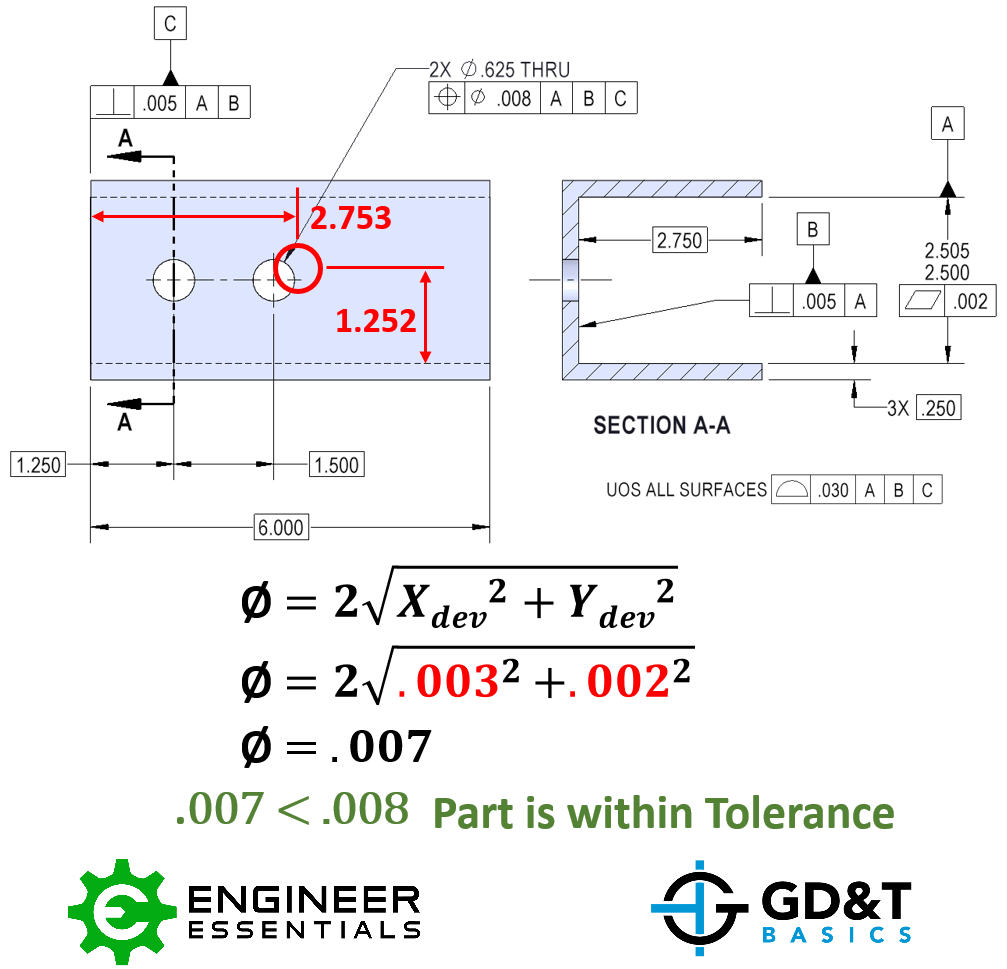
The formula for true position in Geometric Dimensioning and Tolerancing (GD&T) is based on the distance between the actual position of a feature and its theoretical position. This distance is calculated using the coordinates of the feature's actual position and its theoretical position. The true position formula is: True Position = √((x2 - x1)^2 + (y2 - y1)^2), where (x1, y1) are the coordinates of the theoretical position and (x2, y2) are the coordinates of the actual position.
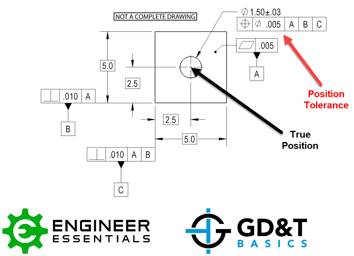
Understanding True Position in GD&T
The concept of true position is crucial in GD&T as it helps to determine the accuracy of a feature's position. True position is the distance between the actual position of a feature and its theoretical position, and it is calculated using the coordinates of the two positions. The formula for true position is used to calculate this distance, which is then compared to the tolerance specified in the GD&T specification.
- The theoretical position is the ideal position of a feature as specified in the design.
- The actual position is the position of the feature as it is actually manufactured.
- The distance between the two positions is calculated using the true position formula.
Calculating True Position
To calculate the true position, the coordinates of the actual and theoretical positions must be known. The true position formula is then applied to these coordinates to calculate the distance between the two positions. The formula is: True Position = √((x2 - x1)^2 + (y2 - y1)^2), where (x1, y1) are the coordinates of the theoretical position and (x2, y2) are the coordinates of the actual position.
- X and y coordinates are used to calculate the true position.
- The square root of the sum of the squares of the differences in x and y coordinates is calculated.
- The result is the true position of the feature.
Importance of True Position in GD&T
The concept of true position is critical in GD&T as it helps to ensure that the features of a part are accurately positioned. True position is used to verify that the part meets the specifications and tolerances specified in the design. The true position formula is used to calculate the distance between the actual and theoretical positions, which is then compared to the tolerance.
- Accuracy is crucial in GD&T, and true position helps to ensure accuracy.
- Tolerances are specified in the design to ensure that the part meets the requirements.
- Verification of the part's true position is necessary to ensure that it meets the specifications.
Applications of True Position in GD&T
The concept of true position has numerous applications in GD&T, including inspection, verification, and manufacturing. True position is used to check that the features of a part are accurately positioned, and it is also used to verify that the part meets the specifications and tolerances.
- Inspection is an important application of true position, where the part is checked for accuracy.
- Verification is another application, where the part is verified to meet the specifications.
- Manufacturing is also an application, where true position is used to ensure that the part is accurately manufactured.
Best Practices for Using True Position in GD&T
To get the most out of the concept of true position in GD&T, it is essential to follow best practices. This includes specifying the true position tolerance in the design, calculating the true position using the formula, and verifying that the part meets the specifications.
- Specify the true position tolerance in the design to ensure accuracy.
- Calculate the true position using the formula to ensure correctness.
- Verify that the part meets the specifications to ensure compliance.
How to calculate position in cmm?

To calculate position in CMM (Coordinate Measuring Machine), you need to understand the basics of coordinate geometry and how it applies to the machine's movement. The CMM uses probes to measure the position of a workpiece in a three-dimensional space. The machine's controller calculates the position of the probe based on the coordinate system used, which is typically a Cartesian coordinate system.
Understanding Coordinate Systems
To calculate position in CMM, you need to understand how coordinate systems work. A coordinate system is a way of describing the position of a point in space using numbers. In a Cartesian coordinate system, each point is represented by three coordinates: X, Y, and Z. The CMM uses these coordinates to determine the position of the probe. Here are some key points to understand:
- The origin of the coordinate system is the point where the X, Y, and Z axes intersect.
- The X-axis represents the horizontal movement of the probe.
- The Y-axis represents the vertical movement of the probe.
Calibrating the CMM
Before calculating position in CMM, you need to calibrate the machine. Calibration involves setting the zero point of the coordinate system and ensuring that the machine's axes are aligned properly. This is typically done using a calibration artifact and software that comes with the machine. Here are some steps involved in calibration:
- Mounting the calibration artifact on the machine's table.
- Setting the zero point of the coordinate system.
- Checking the alignment of the machine's axes.
Measuring Position with CMM
To measure position in CMM, you need to use the probe to touch the workpiece at various points. The machine's controller calculates the position of the probe based on the coordinate system used. Here are some key points to understand:
- The probe is moved to the desired location on the workpiece.
- The controller calculates the position of the probe based on the coordinate system.
- The position is displayed on the machine's screen.
Using Software for CMM
To calculate position in CMM, you need to use software that comes with the machine. The software allows you to control the machine's movement and calculate the position of the probe. Here are some features of CMM software:
- Graphical user interface to control the machine's movement.
- Coordinate calculation to determine the position of the probe.
- Data analysis to evaluate the measurement results.
Troubleshooting CMM Errors
To ensure accurate position calculation in CMM, you need to troubleshoot any errors that may occur. Here are some common errors and how to troubleshoot them:
- Machine calibration errors can be fixed by recalibrating the machine.
- Probe errors can be fixed by checking the probe's alignment and cleanliness.
- Software errors can be fixed by checking the software settings and updating the software.
How do you calculate 3D true position?
To calculate the 3D true position, you need to consider the X, Y, and Z coordinates of an object in a three-dimensional space. This calculation is crucial in various fields such as geometrics, navigation, and computer-aided design. The process involves determining the precise location of an object in 3D space, taking into account the orientation and position of the object.
Understanding 3D Coordinate Systems
The calculation of 3D true position requires a thorough understanding of 3D coordinate systems, which provide a framework for describing the location of objects in three-dimensional space. The most common 3D coordinate system is the Cartesian coordinate system, which uses three perpendicular axes (X, Y, and Z) to define the position of an object. To calculate the 3D true position, you need to:
- Determine the X, Y, and Z coordinates of the object.
- Consider the orientation of the object in 3D space.
- Apply geometric transformations to calculate the true position of the object.
Geometric Transformations in 3D Space
Geometric transformations, such as translations, rotations, and scalings, play a crucial role in calculating the 3D true position. These transformations allow you to manipulate the object's position and orientation in 3D space, enabling you to determine its precise location. To perform these transformations, you need to:
- Apply matrix operations to represent the transformations.
- Use quaternions or Euler angles to describe the object's orientation.
- Perform vector calculations to determine the object's position.
Applications of 3D True Position Calculation
The calculation of 3D true position has numerous applications in various fields, including computer-aided design, navigation, and geometrics. In computer-aided design, 3D true position calculation is used to create precise models of objects and simulate their behavior in different scenarios. To apply 3D true position calculation in these fields, you need to:
- Use software tools specifically designed for 3D modeling and simulation.
- Understand the mathematical concepts underlying 3D true position calculation.
- Consider the physical constraints of the objects being modeled.
Challenges in 3D True Position Calculation
Calculating the 3D true position can be challenging due to various factors, such as noise and uncertainty in the data, non-linear transformations, and complex geometries. To overcome these challenges, you need to:
- Use robust algorithms that can handle noisy data.
- Apply filtering techniques to reduce the effects of noise.
- Consider alternative representations of the object's position and orientation.
Future Developments in 3D True Position Calculation
The field of 3D true position calculation is constantly evolving, with new technologies and methodologies being developed to improve the accuracy and efficiency of these calculations. To stay up-to-date with the latest developments, you need to:
- Follow research papers and academic journals in the field.
- Participate in conferences and workshops related to 3D true position calculation.
- Explore new software tools and hardware platforms that can aid in 3D true position calculation.
How to calculate GDT?
To calculate GDT (Global Distance Test), one needs to understand the concept of distance and how it applies to the problem at hand. The GDT is a measure used to evaluate the accuracy of a predicted structure by comparing it to the native structure. This is done by calculating the distance between corresponding atoms in the two structures.
Understanding the Basics of GDT Calculation
The GDT calculation involves determining the percentage of atoms that fall within a certain distance threshold. This threshold is typically set to a specific value, such as 1, 2, 4, or 8 angstroms. The calculation takes into account the distance between corresponding atoms in the predicted and native structures. The GDT score is then calculated as the percentage of atoms that fall within the specified distance threshold.
- The GDT score is calculated using the LGA (Local-Global Alignment) algorithm, which aligns the predicted structure with the native structure.
- The distance threshold is set to a specific value, such as 1, 2, 4, or 8 angstroms.
- The percentage of atoms that fall within the specified distance threshold is calculated to obtain the GDT score.
Importance of Distance Threshold in GDT Calculation
The distance threshold is a crucial parameter in GDT calculation, as it determines the stringency of the comparison between the predicted and native structures. A lower threshold value, such as 1 angstrom, will result in a more stringent comparison, while a higher threshold value, such as 8 angstroms, will result in a more lenient comparison.
- A lower threshold value will result in a more stringent comparison, which may penalize small deviations in the predicted structure.
- A higher threshold value will result in a more lenient comparison, which may reward larger deviations in the predicted structure.
- The choice of distance threshold depends on the specific application and the desired level of stringency.
Role of LGA Algorithm in GDT Calculation
The LGA algorithm plays a critical role in GDT calculation, as it aligns the predicted structure with the native structure. This alignment is necessary to ensure that the distance between corresponding atoms is calculated correctly. The LGA algorithm uses a combination of local and global alignments to optimize the alignment of the two structures.
- The LGA algorithm uses a combination of local and global alignments to optimize the alignment of the two structures.
- The alignment is necessary to ensure that the distance between corresponding atoms is calculated correctly.
- The LGA algorithm is robust and can handle complex structures with multiple domains.
Interpretation of GDT Scores
The GDT score is a measure of the accuracy of the predicted structure, with higher scores indicating better accuracy. The GDT score can be interpreted as the percentage of atoms that fall within the specified distance threshold.
- A GDT score of 90% indicates that 90% of the atoms in the predicted structure are within the specified distance threshold of the corresponding atoms in the native structure.
- A GDT score of 50% indicates that 50% of the atoms in the predicted structure are within the specified distance threshold of the corresponding atoms in the native structure.
- The GDT score can be used to compare the accuracy of different predictions.
Applications of GDT Calculation
The GDT calculation has several applications in structural biology, including protein structure prediction, protein-ligand docking, and protein-protein docking. The GDT score can be used to evaluate the accuracy of predicted structures and to compare the performance of different prediction methods.
- The GDT score can be used to evaluate the accuracy of predicted structures.
- The GDT score can be used to compare the performance of different prediction methods.
- The GDT calculation is a useful tool for structural biologists and computational biologists.
Frequently Asked Questions (FAQs)
What is the purpose of the GD&T Spherical True Position Tolerance Calculator and Equation?
The GD&T Spherical True Position Tolerance Calculator and Equation is a tool used to calculate the tolerance of a spherical feature in a geometric dimensioning and tolerancing (GD&T) system. The main purpose of this calculator is to determine the maximum and minimum limits of a spherical feature, such as a ball or a sphere, within a specified tolerance zone. This is important in engineering and manufacturing applications, where precision and accuracy are critical. By using the GD&T Spherical True Position Tolerance Calculator and Equation, engineers and manufacturers can ensure that their products meet the required specifications and standards, which is essential for safety, reliability, and performance.
How does the GD&T Spherical True Position Tolerance Calculator and Equation work?
The GD&T Spherical True Position Tolerance Calculator and Equation works by using a set of mathematical formulas and algorithms to calculate the tolerance of a spherical feature. The calculator takes into account various input parameters, such as the diameter of the sphere, the tolerance zone, and the datum features. These parameters are then used to calculate the maximum and minimum limits of the spherical feature, which are represented by a set of coordinates and vectors. The calculator also takes into account the orientation and position of the sphere in relation to the datum features, which is critical in determining the tolerance of the feature. By using the GD&T Spherical True Position Tolerance Calculator and Equation, users can quickly and accurately calculate the tolerance of a spherical feature, which saves
What are the benefits of using the GD&T Spherical True Position Tolerance Calculator and Equation?
The GD&T Spherical True Position Tolerance Calculator and Equation offers several benefits to users, including increased accuracy and precision in calculating the tolerance of spherical features. The calculator also saves
How can I apply the GD&T Spherical True Position Tolerance Calculator and Equation in real-world applications?
The GD&T Spherical True Position Tolerance Calculator and Equation can be applied in a variety of real-world applications, including design, manufacturing, and quality control. For example, in the aerospace industry, the calculator can be used to ensure that spherical bearings and ball joints meet the required tolerance specifications. In the automotive industry, the calculator can be used to design and manufacture spherical components, such as ball-and-socket joints and spherical bearings. In medical devices, the calculator can be used to ensure that spherical components, such as ball-and-socket joints and spherical bearings, meet the required tolerance specifications for safety and reliability. By applying the GD&T Spherical True Position Tolerance Calculator and Equation in real-world applications, users can ensure that their products meet the required specifications and standards, which is essential for safety, reliability, and performance.
Deja una respuesta
Entradas Relacionadas