
Forced Air Flow Convection Cooling Fan Air Flow Required Equations and Calculator

Forced air flow convection cooling is a crucial process in various industrial and electronic applications, where heat dissipation is essential for maintaining optimal performance and preventing damage. The air flow required for effective cooling depends on several factors, including the heat source, ambient temperature, and desired cooling rate. To determine the necessary air flow, engineers and technicians rely on specific equations and calculators that take into account these variables, ensuring efficient and reliable cooling systems. This article explores the key equations and calculator tools used in forced air flow convection cooling applications.
-
Forced Air Flow Convection Cooling Fan Air Flow Required Equations and Calculator
- Introduction to Forced Air Flow Convection Cooling
- Forced Air Flow Convection Cooling Fan Air Flow Required Equations
- Forced Air Flow Convection Cooling Fan Air Flow Required Calculator
- Importance of Fan Efficiency in Forced Air Flow Convection Cooling
- Applications of Forced Air Flow Convection Cooling
-
How do you calculate forced air flow rate?
- Understanding the Basics of Forced Air Flow Rate
- Calculating Forced Air Flow Rate using the Continuity Equation
- Using the Bernoulli's Equation to Calculate Forced Air Flow Rate
- Accounting for Frictional Losses in Forced Air Flow Rate Calculations
- Using Computational Fluid Dynamics to Calculate Forced Air Flow Rate
- What is the equation for air flow cooling?
- What is the formula for fan air flow rate?
- What is the equation for fan flow?
-
Frequently Asked Questions (FAQs)
- What is Forced Air Flow Convection Cooling and How Does it Work?
- What are the Key Factors that Affect the Required Air Flow in Forced Air Flow Convection Cooling?
- How are the Equations for Forced Air Flow Convection Cooling Derived and What are the Assumptions?
- What are the Limitations and Challenges of Using Forced Air Flow Convection Cooling, and How Can they be Overcome?
Forced Air Flow Convection Cooling Fan Air Flow Required Equations and Calculator
Forced air flow convection cooling is a method used to dissipate heat from electronic devices, machinery, and other equipment. It involves the use of a fan to circulate air over the surface of the device, thereby increasing the rate of heat transfer. The air flow required for effective cooling depends on several factors, including the power consumption of the device, the temperature difference between the device and the surrounding air, and the heat transfer coefficient. The Forced Air Flow Convection Cooling Fan Air Flow Required Equations and Calculator can be used to determine the required air flow rate and fan performance.
Introduction to Forced Air Flow Convection Cooling
Forced air flow convection cooling is a widely used method for cooling electronic devices, machinery, and other equipment. It is a simple and effective way to increase the rate of heat transfer from the device to the surrounding air. The fan used in forced air flow convection cooling can be either a centrifugal fan or an axial fan, depending on the application and the required air flow rate. The air flow rate required for effective cooling can be calculated using the Forced Air Flow Convection Cooling Fan Air Flow Required Equations and Calculator.
Forced Air Flow Convection Cooling Fan Air Flow Required Equations
The air flow required for forced air flow convection cooling can be calculated using the following equations:
Q = (P / (ρ Cp ΔT)) (1 / η)
where:
Q = air flow rate (m³/s)
P = power consumption (W)
ρ = air density (kg/m³)
Cp = specific heat capacity of air (J/kg°C)
ΔT = temperature difference between the device and the surrounding air (°C)
η = fan efficiency
These equations can be used to determine the required air flow rate and fan performance.
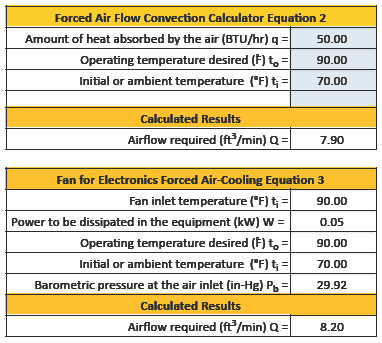
Forced Air Flow Convection Cooling Fan Air Flow Required Calculator
The Forced Air Flow Convection Cooling Fan Air Flow Required Calculator is a tool used to calculate the required air flow rate and fan performance. It takes into account the power consumption of the device, the temperature difference between the device and the surrounding air, and the heat transfer coefficient. The calculator can be used to determine the required air flow rate, fan speed, and fan power consumption.
| Parameter | Unit | Value |
|---|---|---|
| Power consumption | W | 100 |
| Temperature difference | °C | 20 |
| Air density | kg/m³ | 1.2 |
| Specific heat capacity of air | J/kg°C | 1005 |
| Fan efficiency | % | 80 |
Importance of Fan Efficiency in Forced Air Flow Convection Cooling
The fan efficiency is an important parameter in forced air flow convection cooling. It determines the amount of energy required to achieve a given air flow rate. A high-efficiency fan can provide the required air flow rate while consuming less power, thereby reducing the overall energy consumption. The fan efficiency can be improved by using a well-designed fan and a properly sized fan.
Applications of Forced Air Flow Convection Cooling
Forced air flow convection cooling has a wide range of applications, including electronic devices, machinery, and industrial equipment. It is used to cool computer servers, data centers, and telecommunication equipment. The Forced Air Flow Convection Cooling Fan Air Flow Required Equations and Calculator can be used to determine the required air flow rate and fan performance for these applications. The use of forced air flow convection cooling can help to increase the reliability and efficiency of these systems, while reducing the energy consumption and cost.
How do you calculate forced air flow rate?
To calculate the forced air flow rate, you need to consider several factors, including the air density, velocity, and cross-sectional area of the duct or pipe through which the air is flowing. The calculation typically involves using the equation: Q = A x V, where Q is the volumetric flow rate, A is the cross-sectional area, and V is the velocity of the air. This equation can be modified to account for air density and other factors, such as pressure and temperature.
Understanding the Basics of Forced Air Flow Rate
The calculation of forced air flow rate is crucial in various applications, including HVAC systems, industrial processes, and aerospace engineering. To calculate the forced air flow rate, you need to understand the basic principles of fluid mechanics and thermodynamics. Some key factors to consider include:
- The type of air flow, whether it is laminar or turbulent, which affects the velocity and pressure of the air.
- The dimensions of the duct or pipe, including the diameter, length, and shape, which affect the cross-sectional area and frictional losses.
- The properties of the air, including its density, viscosity, and specific heat capacity, which affect the velocity and temperature of the air.
Calculating Forced Air Flow Rate using the Continuity Equation
The continuity equation is a fundamental principle in fluid mechanics that states that the mass flow rate of a fluid remains constant throughout a closed system. To calculate the forced air flow rate using the continuity equation, you need to know the density and velocity of the air at different points in the system. Some key steps include:
- Defining the system boundaries, including the inlet and outlet points, and the control volume.
- Applying the continuity equation, which states that the mass flow rate is constant throughout the system.
- Solving for the velocity of the air at different points in the system, using the continuity equation and the equation of state.
Using the Bernoulli's Equation to Calculate Forced Air Flow Rate
Bernoulli's equation is a fundamental principle in fluid mechanics that relates the pressure and velocity of a fluid in a closed system. To calculate the forced air flow rate using Bernoulli's equation, you need to know the pressure and velocity of the air at different points in the system. Some key steps include:
- Defining the system boundaries, including the inlet and outlet points, and the control volume.
- Applying Bernoulli's equation, which states that the total energy of the fluid remains constant throughout the system.
- Solving for the velocity of the air at different points in the system, using Bernoulli's equation and the equation of state.
Accounting for Frictional Losses in Forced Air Flow Rate Calculations
Frictional losses can have a significant impact on the forced air flow rate, particularly in long ducts or pipes with high velocities. To account for frictional losses, you need to consider the friction factor, which depends on the Reynolds number and the roughness of the duct or pipe. Some key steps include:
- Calculating the Reynolds number, which determines the type of air flow, whether it is laminar or turbulent.
- Determining the friction factor, which depends on the Reynolds number and the roughness of the duct or pipe.
- Applying the Darcy-Weisbach equation, which relates the pressure drop to the friction factor and the velocity of the air.
Using Computational Fluid Dynamics to Calculate Forced Air Flow Rate
Computational fluid dynamics (CFD) is a powerful tool for calculating the forced air flow rate in complex systems, such as HVAC systems or industrial processes. To use CFD, you need to create a computational model of the system, including the geometry, boundary conditions, and fluid properties. Some key steps include:
- Creating a computational model, including the geometry and boundary conditions of the system.
- Defining the fluid properties, including the density, viscosity, and specific heat capacity of the air.
- Solving the Navier-Stokes equations, which describe the motion of fluids in the system, using numerical methods such as the finite element method or the finite volume method.
What is the equation for air flow cooling?
The equation for air flow cooling is based on the principle of heat transfer and can be expressed using the formula: Q = (h A) (T_s - T_f), where Q is the heat transfer rate, h is the convective heat transfer coefficient, A is the surface area, T_s is the surface temperature, and T_f is the fluid temperature.
Introduction to Air Flow Cooling
Air flow cooling is a convection cooling method that uses the movement of air to transfer heat away from a surface. This method is widely used in various applications, including electronic devices, automotive systems, and industrial processes. The equation for air flow cooling is used to calculate the heat transfer rate and determine the cooling performance of a system.
- The convective heat transfer coefficient (h) is a critical parameter in the equation, as it depends on the air flow velocity, surface roughness, and fluid properties.
- The surface area (A) also plays a significant role in the equation, as it affects the heat transfer rate and the overall cooling performance.
- The temperature difference (T_s - T_f) is another important factor, as it drives the heat transfer process and determines the cooling capacity of the system.
Factors Affecting Air Flow Cooling
Several factors can affect the air flow cooling performance, including the air flow velocity, surface roughness, fluid properties, and system geometry. The equation for air flow cooling takes into account these factors to provide an accurate calculation of the heat transfer rate.
- The air flow velocity has a significant impact on the convective heat transfer coefficient (h), as it enhances the turbulence and mixing of the fluid.
- The surface roughness also influences the convective heat transfer coefficient (h), as it affects the boundary layer and turbulence characteristics.
- The fluid properties, such as density, viscosity, and specific heat capacity, play a crucial role in determining the heat transfer rate and cooling performance.
Applications of Air Flow Cooling
Air flow cooling has numerous applications in various industries, including electronics, automotive, aerospace, and industrial processes. The equation for air flow cooling is used to design and optimize cooling systems for these applications.
- In electronic devices, air flow cooling is used to dissipate heat generated by components, such as microprocessors and power amplifiers.
- In automotive systems, air flow cooling is used to cool engines, transmissions, and brake systems.
- In industrial processes, air flow cooling is used to cool equipment, such as motors, pumps, and gearboxes.
Design Considerations for Air Flow Cooling
When designing an air flow cooling system, several factors must be considered, including the system geometry, air flow velocity, surface roughness, and fluid properties. The equation for air flow cooling can be used to optimize the cooling performance and minimize energy consumption.
- The system geometry should be designed to maximize the surface area and minimize the pressure drop.
- The air flow velocity should be optimized to achieve the desired cooling performance while minimizing energy consumption.
- The surface roughness should be controlled to ensure a uniform heat transfer coefficient and minimal pressure drop.
Future Developments in Air Flow Cooling
Researchers are continually working to improve the efficiency and effectiveness of air flow cooling systems. New technologies, such as nanostructures and advanced materials, are being developed to enhance the heat transfer coefficient and cooling performance.
- Nanostructures can be used to create high-performance cooling surfaces with enhanced heat transfer coefficients.
- Advanced materials can be used to develop lightweight and high-strength cooling systems with improved thermal management.
- Computational fluid dynamics (CFD) can be used to simulate and optimize air flow cooling systems, reducing the need for experimental testing.
What is the formula for fan air flow rate?
The formula for fan air flow rate is calculated as the product of the density of the air, the velocity of the air, and the area of the fan. Mathematically, this can be expressed as: Q = ρ A V, where Q is the air flow rate, ρ is the density of the air, A is the area of the fan, and V is the velocity of the air.
Understanding Fan Air Flow Rate
The air flow rate is an important parameter in determining the performance of a fan. It is typically measured in cubic feet per minute (CFM) or cubic meters per second (m³/s). To calculate the air flow rate, one needs to know the density of the air, which can be affected by factors such as temperature and humidity. The formula for air flow rate can be used to determine the performance of a fan in various applications, including ventilation systems and cooling systems.
- The air flow rate is affected by the size and shape of the fan.
- The density of the air can be affected by temperature and humidity.
- The velocity of the air is an important factor in determining the air flow rate.
Calculating Fan Air Flow Rate
To calculate the air flow rate, one needs to know the density of the air, the velocity of the air, and the area of the fan. The density of the air can be calculated using the ideal gas law, which states that PV = nRT, where P is the pressure, V is the volume, n is the number of moles, R is the gas constant, and T is the temperature. The velocity of the air can be measured using an anemometer.
- The ideal gas law can be used to calculate the density of the air.
- The velocity of the air can be measured using an anemometer.
- The area of the fan can be calculated using the diameter and width of the fan.
Factors Affecting Fan Air Flow Rate
The air flow rate can be affected by several factors, including the size and shape of the fan, the density of the air, and the velocity of the air. The size and shape of the fan can affect the area of the fan, which in turn affects the air flow rate. The density of the air can be affected by temperature and humidity, which can also affect the air flow rate.
- The size and shape of the fan can affect the air flow rate.
- The density of the air can be affected by temperature and humidity.
- The velocity of the air is an important factor in determining the air flow rate.
Applications of Fan Air Flow Rate
The air flow rate is an important parameter in various applications, including ventilation systems and cooling systems. In ventilation systems, the air flow rate is used to determine the amount of air that needs to be exchanged to maintain a healthy and comfortable indoor air quality. In cooling systems, the air flow rate is used to determine the amount of air that needs to be cooled to maintain a comfortable temperature.
- The air flow rate is used in ventilation systems to determine the amount of air that needs to be exchanged.
- The air flow rate is used in cooling systems to determine the amount of air that needs to be cooled.
- The air flow rate can be affected by the size and shape of the fan.
Measuring Fan Air Flow Rate
The air flow rate can be measured using various methods, including the use of an anemometer or a flow meter. An anemometer measures the velocity of the air, while a flow meter measures the volume of air that flows through a given area. The air flow rate can also be calculated using the density of the air, the velocity of the air, and the area of the fan.
- An anemometer can be used to measure the velocity of the air.
- A flow meter can be used to measure the volume of air that flows through a given area.
- The air flow rate can be calculated using the density of the air, the velocity of the air, and the area of the fan.
What is the equation for fan flow?
The equation for fan flow is given by the fan law, which states that the volume flow rate (Q) of a fan is directly proportional to the rotational speed (N) of the fan and the density (ρ) of the air. The equation is: Q = (N × π × D^2 × BHP) / (1000 × ρ), where D is the diameter of the fan and! BHP is the brake horsepower.
Understanding Fan Flow Rate
The fan flow rate is an important parameter in determining the performance of a fan. It is typically measured in cubic feet per minute (CFM) or cubic meters per second (m^3/s). To calculate the fan flow rate, the following factors need to be considered:
- Fan size: The larger the fan, the higher the flow rate.
- Rotational speed: Increasing the rotational speed of the fan increases the flow rate.
- Air density: The density of the air affects the flow rate, with denser air resulting in a lower flow rate.
Factors Affecting Fan Flow
Several factors can affect the fan flow rate, including temperature, humidity, and air pressure. Changes in these factors can impact the density of the air, which in turn affects the fan flow rate. For example, an increase in temperature can decrease the air density, resulting in a higher flow rate. The following factors can impact fan flow:
- Temperature: An increase in temperature decreases the air density, increasing the flow rate.
- Humidity: High! humidity can decrease the air density, increasing the flow rate.
- Air pressure: Changes in air pressure can affect the fan flow rate, with higher pressure resulting in a lower flow rate.
Calculating Fan Flow Rate
To calculate the fan flow rate, the following equation can be used: Q = (N × π × D^2 × BHP) / (1000 × ρ). This equation takes into account the rotational speed (N), diameter (D), brake horsepower (BHP), and air density (ρ). The following steps are involved in calculating the fan flow rate:
- Determine the fan size: Measure the diameter of the fan.
- Determine the rotational speed: Measure the rotational speed of the fan.
- Determine the brake horsepower: Measure the brake horsepower of the fan.
Applications of Fan Flow Rate
The fan flow rate has several industrial applications, including ventilation systems, air conditioning systems, and heat exchangers. In these applications, the fan flow rate is critical in determining the performance of the system. The following are some of the applications of fan flow rate:
- Ventilation systems: Fan flow rate is used to determine the ventilation rate required to remove contaminants from a building.
- Air conditioning systems: Fan flow rate is used to determine the cooling capacity of an air conditioning system.
- Heat exchangers: Fan flow rate is used to determine the heat transfer rate in a heat exchanger.
Measuring Fan Flow Rate
The fan flow rate can be measured using various methods, including anemometers, flow meters, and pressure gauges. These methods measure the velocity or pressure of the air to determine the flow rate. The following are some of the methods used to measure fan flow rate:
- Anemometers: Measure the velocity of the air to determine the flow rate.
- Flow meters: Measure the volume flow rate of the air.
- Pressure gauges: Measure the pressure of the air to determine the flow rate.
Frequently Asked Questions (FAQs)
What is Forced Air Flow Convection Cooling and How Does it Work?
Forced air flow convection cooling is a heat transfer mechanism that uses a fan or blower to circulate air over a heat source, such as an electronic component or a mechanical system. This circulation of air enhances the convection process, allowing for more efficient heat dissipation. The fan or blower creates a pressure difference that drives the air flow, which in turn, carries heat away from the heat source. The air flow rate and velocity play a crucial role in determining the effectiveness of the cooling system. By using forced air flow convection cooling, the temperature of the heat source can be reduced, increasing its reliability and lifespan. The equations used to calculate the required air flow take into account factors such as the heat load, temperature difference, and air properties, including density and specific heat capacity.
What are the Key Factors that Affect the Required Air Flow in Forced Air Flow Convection Cooling?
The required air flow in forced air flow convection cooling is influenced by several key factors, including the heat load, temperature difference, air properties, and system geometry. The heat load is the amount of heat that needs to be dissipated, and it is typically measured in watts. The temperature difference is the difference between the temperature of the heat source and the ambient temperature. The air properties, such as density and specific heat capacity, also play a crucial role in determining the required air flow. Additionally, the system geometry, including the size and shape of the heat source and the surrounding enclosure, can affect the air flow pattern and heat transfer rates. By understanding these factors, engineers can design more efficient and effective cooling systems using forced air flow convection cooling. The calculator can be used to determine the required air flow based on these factors, ensuring that the cooling system is properly sized and configured.
How are the Equations for Forced Air Flow Convection Cooling Derived and What are the Assumptions?
The equations for forced air flow convection cooling are derived from the fundamentals of heat transfer and fluid dynamics. The equations are based on the conservation of energy and momentum, and they take into account the complexity of the fluid flow and heat transfer processes. The assumptions used to derive the equations include the steadiness of the flow, the uniformity of the temperature and velocity distributions, and the negligible effects of radiation and natural convection. Additionally, the equations assume that the air is an ideal gas, and that the flow is turbulent. By making these assumptions, the equations can be simplified and solved using mathematical techniques, providing a useful tool for engineers to design and optimize cooling systems using forced air flow convection cooling. The calculator uses these equations to calculate the required air flow, ensuring that the cooling system is properly designed and configured.
What are the Limitations and Challenges of Using Forced Air Flow Convection Cooling, and How Can they be Overcome?
While forced air flow convection cooling is a effective and efficient method of heat transfer, it also has several limitations and challenges. One of the main limitations is the noise generated by the fan or blower, which can be a concern in quiet environments. Additionally, the energy consumption of the fan or blower can be a significant contributor to the overall power consumption of the system. Furthermore, the complexity of the system geometry and the non-linear nature of the heat transfer and fluid flow processes can make it challenging to optimize the cooling system. To overcome these limitations and challenges, engineers can use advanced numerical methods, such as computational fluid dynamics (CFD), to simulate and optimize the cooling system. Additionally, the use of high-efficiency fans and blowers, as well as advanced materials and design techniques, can help to minimize the noise and energy consumption of the cooling system. By understanding these limitation and challenges, engineers can design more efficient, effective, and reliable cooling systems using forced air flow convection cooling.
Deja una respuesta
Entradas Relacionadas