
Fluid Energy Loss in Fittings and Valves Formula, Calculator and Tables

Fluid energy loss in fittings and valves is a critical aspect of piping system design, as it can significantly impact the overall efficiency and performance of the system. The energy lost due to friction and turbulence in fittings and valves can lead to increased pumping costs and reduced system reliability. To accurately calculate and minimize these losses, engineers rely on formulas, calculators, and tables that provide a comprehensive understanding of the complex interactions between fluid flow, pipe geometry, and valve characteristics, enabling the optimization of piping systems for various industrial applications. Accurate calculations are essential for system design.
- Understanding Fluid Energy Loss in Fittings and Valves
- How do you calculate fitting loss?
- What is the formula for energy loss in fluid mechanics?
- Which formula is used to calculate head loss in valves?
- What is the pressure loss across fittings?
-
Frequently Asked Questions (FAQs)
- What is the significance of calculating Fluid Energy Loss in Fittings and Valves?
- How is the Fluid Energy Loss in Fittings and Valves calculated using the formula?
- What are the advantages of using a Fluid Energy Loss Calculator and Tables?
- How can the Fluid Energy Loss in Fittings and Valves be minimized or reduced?
Understanding Fluid Energy Loss in Fittings and Valves
Fluid energy loss in fittings and valves is a critical aspect of fluid dynamics that affects the overall efficiency of a system. The loss of energy occurs due to the resistance and turbulence created by the fittings and valves, which can lead to a significant decrease in the pressure and flow rate of the fluid. This loss of energy can result in increased pumping costs and decreased system performance.
Fluid Energy Loss Formula
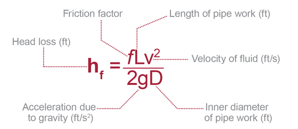
The fluid energy loss in fittings and valves can be calculated using the Darcy-Weisbach equation, which takes into account the friction factor, length, and diameter of the pipe, as well as the density and velocity of the fluid. The equation is as follows:
h = (f L v^2) / (2 g D)
where h is the head loss, f is the friction factor, L is the length of the pipe, v is the velocity of the fluid, g is the acceleration due to gravity, and D is the diameter of the pipe.
Calculator for Fluid Energy Loss
A calculator for fluid energy loss can be used to simplify the calculation process. The calculator typically requires input values such as the flow rate, pressure, temperature, and fluid properties, and then uses the Darcy-Weisbach equation to calculate the head loss. The calculator can also take into account the type of fitting or valve and its equivalent length to provide a more accurate calculation.
Tables for Fluid Energy Loss
Tables are often used to provide a quick and easy way to determine the fluid energy! loss in fittings and valves. The tables typically list the equivalent length of different types of fittings and valves, as well as the friction factor and head loss coefficient for each. The tables can be used in conjunction with the Darcy-Weisbach equation to calculate the head loss.
| Fitting/Valve | Equivalent Length (L/D) | Friction Factor (f) | Head Loss Coefficient (K) |
|---|---|---|---|
| Elbow | 30 | 0.02 | 0.5 |
| Tee | 20 | 0.015 | 0.3 |
| Valve | 10 | 0.01 | 0.2 |
Factors Affecting Fluid Energy Loss
Several factors can affect the fluid energy loss in fittings and valves, including the type of fitting or valve, flow rate, pressure, temperature, and fluid properties. The surface roughness of the pipe and fittings can also affect the friction factor and head loss. Additionally, the orientation and installation of the fittings and valves can impact the fluid energy loss.
Minimizing Fluid Energy Loss
To minimize fluid energy loss, it is essential to select the right type of fitting or valve for the application, as well as to ensure proper installation and maintenance. The use of energy-efficient fittings and valves, such as those with low friction or self-cleaning designs, can also help reduce fluid energy loss. Furthermore, optimizing the system design and sizing the pipes and fittings correctly can also help minimize fluid energy loss and reduce pumping costs. The use of computational fluid dynamics (CFD) can also help optimize the system design and minimize fluid energy loss.
How do you calculate fitting loss?
To calculate fitting loss, you need to understand the concept of overfitting and underfitting in machine learning models. Fitting loss refers to the difference between the predicted values and the actual values of a model. It is a measure of how well a model fits the training data. The mean squared error (MSE) is a common metric used to calculate fitting loss. It is calculated by taking the average of the squared differences between the predicted and actual values.
Understanding Fitting Loss
Fitting loss is an essential concept in machine learning, as it helps to evaluate the performance of a model. A low fitting loss indicates that the model is a good fit for the training data, while a high fitting loss indicates that the model is not a good fit. To calculate fitting loss, you need to have a deep understanding of the model's architecture and the data it is being trained on. Some key points to consider when calculating fitting loss include:
- Data quality: The quality of the data can significantly impact the fitting loss. Noisy or missing data can increase the fitting loss.
- Model complexity: The complexity of the model can also impact the fitting loss. A simple model may not be able to capture the underlying patterns in the data, resulting in a high fitting loss.
- Regularization techniques: Regularization techniques, such as L1 and L2 regularization, can help to reduce overfitting and improve the fitting loss.
Calculating Fitting Loss using Mean Squared Error (MSE)
The mean squared error (MSE) is a widely used metric for calculating fitting loss. It is calculated by taking the average of the squared differences between the predicted and actual values. The MSE is a good indicator of the model's performance, as it is sensitive to outliers. To calculate the MSE, you need to follow these steps:
- Predict the values using the model.
- Calculate the squared differences between the predicted and actual values.
- Take the average of the squared differences.
Impact of Overfitting on Fitting Loss
Overfitting can have a significant impact on the fitting loss. When a model is overfitting, it is too complex and is able to capture the noise in the training data. This results in a low fitting loss on the training data, but a high fitting loss on the test data. To avoid overfitting, you can use regularization techniques, such as L1 and L2 regularization, or early stopping. Some key points to consider when dealing with overfitting include:
- Model complexity: Reduce the complexity of the model to avoid overfitting.
- Regularization techniques: Use regularization techniques to reduce overfitting.
- Early stopping: Use early stopping to stop training when the model starts to overfit.
Impact of Underfitting on Fitting Loss
Underfitting can also have a significant impact on the fitting loss. When a model is underfitting, it is too simple and is not able to capture the underlying patterns in the data. This results in a high fitting loss on both the training and test data. To avoid underfitting, you can increase the complexity of the model or collect more data. Some key points to consider when dealing with underfitting include:
- Model complexity: Increase the complexity of the model to avoid underfitting.
- Collect more data: Collect more data to help the model learn the underlying patterns.
- Feature engineering: Use feature engineering to create new features that can help the model learn the underlying patterns.
Techniques for Reducing Fitting Loss
There are several techniques that can be used to reduce fitting loss. Some of these techniques include:
- Regularization techniques: Use regularization techniques, such as L1 and L2 regularization, to reduce overfitting.
- Early stopping: Use early stopping to stop training when the model starts to overfit.
- Data augmentation: Use data augmentation to increase the size of the training data and help the model learn the underlying patterns.
What is the formula for energy loss in fluid mechanics?

The formula for energy loss in fluid mechanics is based on the Darcy-Weisbach equation, which is a widely used equation in the field of fluid mechanics to calculate the head loss or energy loss in a pipe flow. The equation is given by: h = (f L v^2) / (2 g D), where h is the head loss, f is the friction factor, L is the length of the pipe, v is the average velocity of the fluid, g is the acceleration due to gravity, and D is the diameter of the pipe.
Understanding the Darcy-Weisbach Equation
The Darcy-Weisbach equation is a fundamental equation in fluid mechanics that helps to calculate the energy loss in a pipe flow. The equation takes into account the friction factor, which is a dimensionless quantity that depends on the Reynolds number and the roughness of the pipe. The equation also considers the length and diameter of the pipe, as well as the average velocity of the fluid. Some key points to consider when applying the Darcy-Weisbach equation include:
- The friction factor can be determined using the Moody chart or other empirical correlations.
- The Reynolds number is a dimensionless quantity that characterizes the nature of the flow, and it is defined as Re = (ρ v D) / μ, where ρ is the density of the fluid, v is the average velocity, D is the diameter of the pipe, and μ is the dynamic viscosity of the fluid.
- The roughness of the pipe can significantly affect the friction factor and the energy loss in the pipe flow.
Factors Affecting Energy Loss in Pipe Flow
There are several factors that can affect the energy loss in a pipe flow, including the velocity of the fluid, the diameter and length of the pipe, and the roughness of the pipe. Other factors, such as the density and viscosity of the fluid, can also play a significant role in determining the energy loss. Some key factors to consider include:
- The velocity of the fluid is a critical factor in determining the energy loss, as it affects the Reynolds number and the friction factor.
- The diameter and length of the pipe can significantly affect the energy loss, as they determine the surface area and volume of the fluid in the pipe.
- The roughness of the pipe can increase the energy loss by creating turbulence and friction in the flow.
Types of Energy Loss in Fluid Mechanics
There are several types of energy loss that can occur in fluid mechanics, including frictional losses, minor losses, and major losses. Frictional losses occur due to the friction between the fluid and the pipe wall, while minor losses occur due to turbulence and separation of the flow. Major losses occur due to changes in direction or expansions in the pipe. Some key types of energy loss include:
- Frictional losses are the most significant type of energy loss in pipe flow, and they can be calculated using the Darcy-Weisbach equation.
- Minor losses can occur due to fittings, valves, and other obstructions in the pipe, and they can be calculated using empirical correlations.
- Major losses can occur due to changes in direction or expansions in the pipe, and they can be calculated using continuity and momentum equations.
Applications of the Darcy-Weisbach Equation
The Darcy-Weisbach equation has a wide range of applications in fluid mechanics, including the design of pipe networks, pumping systems, and turbomachinery. The equation can be used to calculate the head loss or energy loss in a pipe flow, which is critical in determining the pumping power required to overcome the losses. Some key applications include:
- The design of pipe networks for water supply, sewage, and industrial applications.
- The design of pumping systems for irrigation, cooling, and heating applications.
- The design of turbomachinery, such as pumps, turbines, and compressors.
Limitations of the Darcy-Weisbach Equation
The Darcy-Weisbach equation has several limitations, including its empirical nature and its limited range of applicability. The equation is based on experimental correlations and dimensional analysis, and it may not be applicable to all types of pipe flow or fluid properties. Some key limitations include:
- The equation is empirical and dimensionally inconsistent, which can limit its accuracy and applicability.
- The equation is limited to turbulent flow and may not be applicable to laminar flow or transition flow.
- The equation may not be applicable to non-Newtonian fluids or complex pipe geometries.
Which formula is used to calculate head loss in valves?
The formula used to calculate head loss in valves is the Darcy-Weisbach equation, which is given by: h = (f L v^2) / (2 g D), where h is the head loss, f is the friction factor, L is the length of the valve, v is the velocity of the fluid, g is the acceleration due to gravity, and D is the diameter of the valve.
Understanding the Darcy-Weisbach Equation
The Darcy-Weisbach equation is a widely used formula for calculating head loss in valves and other piping components. To apply this equation, it is essential to understand the physical properties of the fluid, such as its density and viscosity, as well as the geometric characteristics of the valve, including its length, diameter, and roughness. The following are key factors to consider when using the Darcy-Weisbach equation:
- Friction factor: The friction factor, f, is a dimensionless quantity that depends on the Reynolds number and the roughness of the valve.
- Velocity: The velocity, v, of the fluid is a critical parameter in the Darcy-Weisbach equation, as it affects the kinetic energy of the fluid.
- Diameter: The diameter, D, of the valve is also an essential parameter, as it affects the cross-sectional area of the valve and, therefore, the flow rate of the fluid.
Factors Affecting Head Loss in Valves
Several factors can affect head loss in valves, including the type of valve, its size, and the fluid properties. The following are some key factors to consider:
- Valve type: Different types of valves, such as globe valves, ball valves, and butterfly valves, have distinct flow characteristics that affect head loss.
- Valve size: The size of the valve can significantly impact head loss, as larger valves tend to have lower friction losses.
- Fluid properties: The density and viscosity of the fluid can affect the friction factor and, therefore, the head loss in the valve.
Methods for Reducing Head Loss in Valves
There are several methods for reducing head loss in valves, including optimizing valve size, selecting the right valve type, and minimizing pipe fittings. The following are some strategies to consider:
- Optimize valve size: Selecting the right valve size can help minimize head loss, as larger valves tend to have lower friction losses.
- Select the right valve type: Choosing a valve type with low friction losses, such as a ball valve, can help reduce head loss.
- Minimize pipe fittings: Reducing the number of pipe fittings, such as elbows and tees, can help minimize head loss by reducing turbulence and friction.
Importance of Head Loss Calculations
Head loss calculations are crucial in the design and operation of piping systems, as they help ensure that the system can deliver the required flow rate while minimizing energy losses. The following are some reasons why head loss calculations are essential:
- Energy efficiency: Minimizing head loss can help reduce energy consumption and operating costs.
- System reliability: Accurate head loss calculations can help ensure that the piping system is reliable and efficient, reducing the risk of system failures.
- Cost savings: Optimizing head loss can help reduce capital costs by minimizing the size and complexity of the piping system.
Applications of Head Loss Calculations
Head loss calculations have numerous applications in various industries, including water supply, wastewater treatment, and power generation. The following are some examples of how head loss calculations are used:
- Water distribution systems: Head loss calculations are used to design and operate water distribution systems, ensuring that water pressure and flow rate are sufficient to meet consumer demand.
- Pumping systems: Head loss calculations are used to design and optimize pumping systems, minimizing energy consumption and operating costs.
- Industrial processes: Head loss calculations are used in various industrial processes, such as chemical processing and oil refining, to optimize fluid flow and energy efficiency.
What is the pressure loss across fittings?

The pressure loss across fittings is a critical aspect of fluid dynamics and pipe flow. When a fluid flows through a pipe, it encounters various fittings such as elbows, tees, and valves, which can cause a significant reduction in pressure. This pressure loss is due to the resistance and turbulence created by the fittings, which can lead to a decrease in the overall efficiency of the system.
Factors Affecting Pressure Loss
The pressure loss across fittings is influenced by several factors, including the type and size of the fitting, the flow rate, and the fluid properties. The most significant factor is the type of fitting, as different fittings have varying resistance coefficients. For example, an elbow fitting has a higher resistance coefficient than a tee fitting. Other factors such as pipe roughness and fluid velocity also play a crucial role in determining the pressure loss.
- Fitting type: Different fittings have varying resistance coefficients, which affect the pressure loss.
- Flow rate: An increase in flow rate leads to a higher pressure loss due to increased turbulence.
- Fluid properties: The viscosity and density of the fluid influence the pressure loss, with more viscous fluids experiencing higher losses.
Types of Fittings and Pressure Loss
Various types of fittings are used in piping systems, each with its unique characteristics and pressure loss. For instance, elbow fittings are commonly used to change the direction of flow, but they can cause significant pressure loss due to the sharp turn. On the other hand, tee fittings are used to combine or split flows, and they typically have a lower pressure loss than elbow fittings.
- Elbow fittings: These fittings have a high resistance coefficient due to the sharp turn, resulting in significant pressure loss.
- Tee fittings: Tee fittings have a lower resistance coefficient than elbow fittings, but they can still cause significant pressure loss.
- Valve fittings: Valve fittings, such as gate valves and ball valves, can also cause pressure loss due to the restriction they impose on the flow.
Calculating Pressure Loss
Calculating the pressure loss across fittings is crucial for designing and optimizing piping systems. The Darcy-Weisbach equation is commonly used to calculate the pressure loss in pipes and fittings. This equation takes into account the friction factor, pipe length, and fluid velocity to estimate the pressure loss.
- Darcy-Weisbach equation: This equation is used to calculate the pressure loss in pipes and fittings, taking into account the friction factor, pipe length, and fluid velocity.
- Friction factor: The friction factor is a measure of the resistance to flow, and it is used to calculate the pressure loss.
- Pipe length: The length of the pipe also affects the pressure loss, with longer pipes resulting in higher losses.
Minimizing Pressure Loss
Minimizing pressure loss across fittings is essential to improve the efficiency and performance of piping systems. This can be achieved by using smooth fittings, increasing pipe diameter, and reducing flow rates. Additionally, using pressure loss reduction devices such as expansion fittings can also help minimize pressure loss.
- Smooth fittings: Using smooth fittings can reduce pressure loss by minimizing turbulence and resistance.
- Increasing pipe diameter: Increasing the pipe diameter can reduce pressure loss by reducing the fluid velocity.
- Reducing flow rates: Reducing the flow rate can also minimize pressure loss by reducing turbulence and resistance.
Applications and Considerations
The pressure loss across fittings has significant implications for various industries, including chemical processing, power generation, and water distribution. When designing piping systems, it is essential to consider the pressure loss and fluid dynamics to ensure efficient and safe operation.
- Chemical processing: Pressure loss can affect the reaction rates and product quality in chemical processing applications.
- Power generation: Pressure loss can impact the efficiency and performance of power generation systems, such as pumps and turbines.
- Water distribution: Pressure loss can affect the water supply and pressure in water distribution systems, impacting public health and safety.
Frequently Asked Questions (FAQs)
What is the significance of calculating Fluid Energy Loss in Fittings and Valves?
Calculating Fluid Energy Loss in fittings and valves is crucial in the design and operation of fluid flow systems, including piping networks, hydraulic systems, and mechanical systems. The energy loss in these systems can result in reduced system efficiency, increased pumping costs, and decreased overall performance. By calculating the energy loss in fittings and valves, engineers and designers can optimize system design, reduce friction losses, and minimize the pressure drop that occurs as fluid flows through the system. This is particularly important in applications where fluid flow rates are high, such as in industrial processes, power generation, and water supply systems. Accurate calculation of fluid energy loss also enables the selection of suitable fittings and valves that can withstand the flow rates and pressures encountered in the system, ensuring reliable and efficient operation.
How is the Fluid Energy Loss in Fittings and Valves calculated using the formula?
The calculation of Fluid Energy Loss in fittings and valves involves the use of a formula that takes into account the flow rate, fluid density, viscosity, and geometry of the fitting or valve. The formula typically used is the Darcy-Weisbach equation, which expresses the head loss (or energy loss) in terms of the friction factor, flow velocity, and pipe diameter. The friction factor is calculated using the Colebrook-White equation or the Moody diagram, which depends on the Reynolds number and relative roughness of the pipe. Additionally, loss coefficients are used to account for the energy loss caused by fittings and valves, such as bends, tees, and valves. These loss coefficients are usually determined experimentally or obtained from manufacturer's data. By applying the formula and using the appropriate loss coefficients, engineers can calculate the total energy loss in a piping system, including the energy loss in fittings and valves.
What are the advantages of using a Fluid Energy Loss Calculator and Tables?
Using a Fluid Energy Loss Calculator and Tables offers several advantages in the calculation of energy loss in fittings and valves. The calculator can quickly and accurately calculate the energy loss using the Darcy-Weisbach equation and loss coefficients, saving time and reducing the likelihood of errors. The tables provide a convenient way to look up loss coefficients for different types of fittings and valves, eliminating the need to consult multiple sources or perform complex calculations. Additionally, the calculator and tables can be used to compare the energy loss of different fittings and valves, allowing engineers to select the most efficient options for their system. This can lead to significant energy savings and reduced pumping costs over the life of the system. Furthermore, the calculator and tables can be used to optimize system design, reducing the pressure drop and friction losses that occur as fluid flows through the system.
How can the Fluid Energy Loss in Fittings and Valves be minimized or reduced?
Minimizing or reducing the Fluid Energy Loss in fittings and valves requires careful consideration of several factors, including system design, fittings and valve selection, and operating conditions. One way to reduce energy loss is to use smooth pipes and fittings with low friction factors, such as laminar flow fittings. Additionally, valves with low loss coefficients, such as gate valves or ball valves, can be used to minimize energy loss. Another approach is to optimize the pipe diameter and flow rate to reduce friction losses and pressure drop. Furthermore, system designers can use energy-efficient fittings and valves, such as venturi tubes or flow conditioners, to reduce turbulence and energy loss. By considering these factors and using energy loss calculation tools, engineers can design and operate fluid flow systems that minimize energy loss and reduce operating costs. Regular maintenance and inspection of the system can also help to identify and address any issues that may be contributing to energy loss.
Deja una respuesta
Entradas Relacionadas