
Flow of Compressed Air in Pipes Equation and Calculator

The flow of compressed air in pipes is a crucial aspect of various industrial and commercial applications. Calculating the flow rate and pressure drop of compressed air in pipes is essential for designing and optimizing pneumatic systems. The equation for calculating the flow of compressed air in pipes takes into account factors such as pipe diameter, length, and roughness, as well as air pressure and temperature. This article provides an overview of the equation and a calculator to help engineers and technicians determine the flow of compressed air in pipes with ease and accuracy.
- Understanding the Flow of Compressed Air in Pipes Equation and Calculator
- What is the formula for calculating the size of a compressed air pipe?
- How to measure air flow through a pipe?
- What is the formula for air pressure in a pipe?
-
Frequently Asked Questions (FAQs)
- What is the Flow of Compressed Air in Pipes Equation and Calculator?
- How does the Flow of Compressed Air in Pipes Equation and Calculator work?
- What are the key factors that affect the Flow of Compressed Air in Pipes Equation and Calculator?
- How can the Flow of Compressed Air in Pipes Equation and Calculator be used in real-world applications?
Understanding the Flow of Compressed Air in Pipes Equation and Calculator
The flow of compressed air in pipes is a complex phenomenon that involves the interaction of several factors, including the pressure and temperature of the air, the diameter and length of the pipe, and the roughness of the pipe surface. The equation for calculating the flow of compressed air in pipes is based on the conservation of mass and energy principles. The equation takes into account the compressibility of air and the friction losses that occur as the air flows through the pipe.
Introduction to Compressed Air Flow Equation
The compressed air flow equation is a mathematical model that describes the behavior of compressed air as it flows through a pipe. The equation is based on the ideal gas law and takes into account the compressibility of air. The equation is commonly used in industrial applications where compressed air is used as a power source. The equation is also used in HVAC systems to calculate the flow rate of compressed air.
Key Factors Affecting Compressed Air Flow
Several factors affect the flow of compressed air in pipes, including the pressure and temperature of the air, the diameter and length of the pipe, and the roughness of the pipe surface. The pressure of the air has a significant impact on the flow rate, with higher pressures resulting in higher flow rates. The temperature of the air also affects the flow rate, with higher temperatures resulting in lower flow rates. The diameter and length of the pipe also affect the flow rate, with larger diameters and shorter lengths resulting in higher flow rates.
Compressed Air Flow Calculator
A compressed air flow calculator is a tool that uses the compressed air flow equation to calculate the flow rate of compressed air in a pipe. The calculator takes into account the pressure, temperature, diameter, and length of the pipe, as well as the roughness of the pipe surface. The calculator is commonly used in industrial applications where compressed air is used as a power source. The calculator is also used in HVAC systems to calculate the flow rate of compressed air.
Applications of Compressed Air Flow Equation
The compressed air flow equation has several applications in industrial processes, including power transmission, HVAC systems, and pneumatic systems. The equation is used to calculate the flow rate of compressed air in pipes, which is essential for designing and optimizing industrial systems. The equation is also used to calculate the pressure drop in pipes, which is essential for designing and optimizing pneumatic systems.
Limitations of Compressed Air Flow Equation
The compressed air flow equation has several limitations, including the assumption of ideal gas behavior and the neglect of heat transfer and mass transfer. The equation is also limited by the accuracy of the input parameters, including the pressure, temperature, diameter, and length of the pipe. The equation is also limited by the complexity of the pipe system, including the presence of valves, fittings, and bends.
| Parameter | Unit | Description |
|---|---|---|
| Pressure | psi | The pressure of the compressed air |
| Temperature | °F | The temperature of the compressed air |
| Diameter | in | The diameter of the pipe |
| Length | ft | The length of the pipe |
| Roughness | - | The roughness of the pipe surface |
What is the formula for calculating the size of a compressed air pipe?
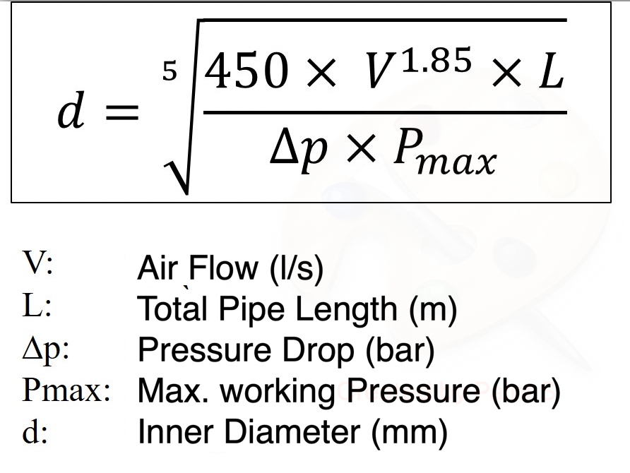
The formula for calculating the size of a compressed air pipe is based on several factors, including the flow rate, pressure, and distance of the pipe. The most common formula used is the Hazen-Williams equation, which takes into account the friction loss and head loss in the pipe. The equation is: Q = 1.318 C D^2.63 (h_f / L)^0.54, where Q is the flow rate, C is the Hazen-Williams coefficient, D is the diameter of the pipe, h_f is the head loss, and L is the length of the pipe.
Factors Affecting Compressed Air Pipe Size
The size of a compressed air pipe is affected by several factors, including the flow rate, pressure, and distance of the pipe. The flow rate is the amount of compressed air that needs to be delivered to the point of use, and it is typically measured in cubic feet per minute (CFM). The pressure of the compressed air is also an important factor, as it affects the flow rate and head loss in the pipe. Other factors that can affect the size of the pipe include the type of pipe material, pipe fittings, and valves.
- The flow rate of the compressed air is the most important factor in determining the size of the pipe.
- The pressure of the compressed air is also an important factor, as it affects the flow rate and head loss in the pipe.
- The type of pipe material can also affect the size of the pipe, as different materials have different friction loss characteristics.
Compressed Air Pipe Materials
The material of the compressed air pipe is an important factor in determining its size and performance. The most common materials used for compressed air pipes are copper, aluminum, and PVC. Each material has its own advantages and disadvantages, and the choice of material will depend on the specific application and requirements of the system.
- Copper is a popular choice for compressed air pipes due to its high strength and corrosion resistance.
- Aluminum is another popular choice, as it is lightweight and corrosion resistant.
- PVC is a cost-effective option, but it may not be suitable for high-pressure applications.
Calculating Compressed Air Pipe Size
To calculate the size of a compressed air pipe, you need to know the flow rate, pressure, and distance of the pipe. You can use the Hazen-Williams equation to calculate the diameter of the pipe. The equation is: Q = 1.318 C D^2.63 (h_f / L)^0.54, where Q is the flow rate, C is the Hazen-Williams coefficient, D is the diameter of the pipe, h_f is the head loss, and L is the length of the pipe.
- First, determine the flow rate of the compressed air in CFM.
- Next, determine the pressure of the compressed air in PSI.
- Then, use the Hazen-Williams equation to calculate the diameter of the pipe.
Compressed Air Pipe Fittings and Valves
The type and number of fittings and valves used in a compressed air pipe can also affect its size and performance. Fittings and valves can cause friction loss and head loss in the pipe, which can affect the flow rate and pressure of the compressed air.
- Fittings such as elbows and tees can cause friction loss and head loss in the pipe.
- Valves such as ball valves and gate valves can also cause friction loss and head loss.
- The number and type of fittings and valves used can affect the overall performance of the system.
Compressed Air Pipe System Design
The design of a compressed air pipe system is critical to its performance and efficiency. A well-designed system will take into account the flow rate, pressure, and distance of the pipe, as well as the type and number of fittings and valves used.
- A well-designed system will ensure that the compressed air is delivered to the point of use at the required pressure and flow rate.
- The system should be designed to minimize friction loss and head loss in the pipe.
- The system should also be designed to be energy efficient and cost effective.
How to measure air flow through a pipe?
To measure air flow through a pipe, you need to use a device that can detect the velocity or pressure of the air flowing through the pipe. There are several methods to measure air flow, including using an anemometer, a pitot tube, or a hot wire anemometer. The choice of method depends on the accuracy and range of measurement required, as well as the environment in which the measurement is being taken.
Types of Air Flow Measurement Devices
There are several types of devices that can be used to measure air flow through a pipe, including mechanical and electronic devices. Some common types of air flow measurement devices include:
- Anemometers, which measure the velocity of the air flow
- Pitot tubes, which measure the pressure difference between two points in the pipe
- Hot wire anemometers, which measure the velocity of the air flow by detecting the cooling effect of the air on a heated wire
Methods for Measuring Air Flow
There are several methods that can be used to measure air flow through a pipe, including direct and indirect methods. Some common methods include:
- Direct measurement, which involves measuring the velocity or pressure of the air flow directly
- Indirect measurement, which involves measuring a related parameter, such as the temperature or humidity of the air
- Calibration, which involves adjusting the measurement device to ensure accuracy and reliability
Factors Affecting Air Flow Measurement
There are several factors that can affect the accuracy of air flow measurements, including pipe size and shape, air temperature and humidity, and flow rate. Other factors that can affect measurement accuracy include:
- Turbulence, which can cause inaccurate measurements if not accounted for
- Leaks or obstructions in the pipe, which can affect the pressure and velocity of the air flow
- Instrument calibration and maintenance, which can affect the accuracy and reliability of the measurement device
Applications of Air Flow Measurement
Air flow measurement is used in a variety of industrial and commercial applications, including HVAC systems, air pollution monitoring, and aerospace engineering. Some common applications include:
- Heating, Ventilation, and Air Conditioning (HVAC) systems, where air flow measurement is used to optimize system performance and energy efficiency
- Air pollution monitoring, where air flow measurement is used to detect and quantify air pollutants
- Aerospace engineering, where air flow measurement is used to test and optimize aircraft and spacecraft systems
Instrumentation for Air Flow Measurement
There are several types of instrumentation that can be used to measure air flow through a pipe, including analog and digital instruments. Some common types of instrumentation include:
- Pressure sensors, which measure the pressure difference between two points in the pipe
- Flow meters, which measure the volume or mass of air flowing through the pipe
- Velocity sensors, which measure the velocity of the air flow
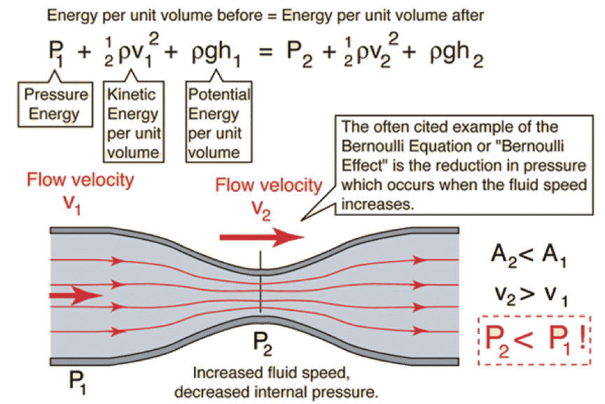
What is the formula for air pressure in a pipe?
The formula for air pressure in a pipe is given by the equation P = (ρ g h) + (0.5 ρ v^2) / (ρ g), where P is the pressure, ρ is the density of the air, g is the acceleration due to gravity, h is the height of the pipe, and v is the velocity of the air.
Understanding the Variables
The variables in the air pressure formula are crucial in determining the pressure in a pipe. To understand the formula, one must first understand the variables involved. The density of the air is a critical variable, as it affects the pressure. The acceleration due to gravity is also important, as it affects the height of the pipe. The velocity of the air is also a key variable, as it affects the pressure. The formula can be broken down into the following components:
- Density: The density of the air is the mass per unit volume of the air.
- Acceleration due to gravity: The acceleration due to gravity is the rate at which an object falls towards the ground.
- Height: The height of the pipe is the distance from the ground to the top of the pipe.
Calculating Air Pressure
To calculate the air pressure in a pipe, one must first determine the values of the variables involved. The density of the air can be determined using a density meter or by looking up the density of air in a table. The acceleration due to gravity is a constant, and the height of the pipe can be measured using a ruler or tape measure. The velocity of the air can be measured using an anemometer. The formula can be used to calculate the pressure in the pipe, and the results can be used to determine the flow rate of the air. The calculation involves the following steps:
- Determine the density: Determine the density of the air using a density meter or by looking up the density of air in a table.
- Measure the height: Measure the height of the pipe using a ruler or tape measure.
- Measure the velocity: Measure the velocity of the air using an anemometer.
Factors Affecting Air Pressure
There are several factors that can affect the air pressure in a pipe. The temperature of the air can affect the density of the air, which in turn affects the pressure. The humidity of the air can also affect the density of the air. The shape and size of the pipe can also affect the pressure, as they can affect the velocity of the air. The friction between the air and the pipe can also affect the pressure. The factors can be summarized as follows:
- Temperature: The temperature of the air can affect the density of the air.
- Humidity: The humidity of the air can affect the density of the air.
- Shape and size: The shape and size of the pipe can affect the velocity of the air.
Applications of the Formula
The formula for air pressure in a pipe has several applications in various fields. In the field of mechanical engineering, the formula is used to design and optimize pneumatic systems. In the field of aerospace engineering, the formula is used to design and optimize aircraft systems. In the field of chemical engineering, the formula is used to design and optimize process systems. The applications can be summarized as follows:
- Mechanical engineering: The formula is used to design and optimize pneumatic systems.
- Aerospace engineering: The formula is used to design and optimize aircraft systems.
- Chemical engineering: The formula is used to design and optimize process systems.
Limitations of the Formula
The formula for air pressure in a pipe has several limitations. The formula assumes that the air is incompressible, which is not always the case. The formula also assumes that the pipe is horizontal, which is not always the case. The formula also assumes that the air is dry, which is not always the case. The limitations can be summarized as follows:
- Incompressible air: The formula assumes that the air is incompressible.
- Horizontal pipe: The formula assumes that the pipe is horizontal.
- Dry air: The formula assumes that the air is dry.
Frequently Asked Questions (FAQs)
What is the Flow of Compressed Air in Pipes Equation and Calculator?
The Flow of Compressed Air in Pipes Equation and Calculator is a mathematical model used to determine the flow rate of compressed air in pipes. This equation takes into account various factors such as the pipe diameter, pipe length, air pressure, and air temperature. The calculator is a tool that simplifies the calculation process by providing a user-friendly interface to input the necessary parameters and obtain the flow rate of compressed air. The equation is based on the principles of fluid dynamics and thermodynamics, which describe the behavior of fluids in motion. By using this equation and calculator, engineers and technicians can design and optimize piping systems for compressed air, ensuring efficient and safe operation.
How does the Flow of Compressed Air in Pipes Equation and Calculator work?
The Flow of Compressed Air in Pipes Equation and Calculator works by using a combination of mathematical formulas and algorithms to calculate the flow rate of compressed air in pipes. The equation takes into account the Reynolds number, which is a dimensionless quantity used to predict laminar or turbulent flow in pipes. The calculator also considers the friction factor, which is a measure of the resistance to flow caused by the pipe walls and fittings. By inputting the necessary parameters, such as pipe diameter, pipe length, air pressure, and air temperature, the calculator can provide an accurate calculation of the flow rate of compressed air. The equation and calculator can be used for a wide range of applications, including industrial processes, HVAC systems, and medical equipment. By understanding how the equation and calculator work, users can make informed decisions about pipe sizing, air compressor selection, and system design.
What are the key factors that affect the Flow of Compressed Air in Pipes Equation and Calculator?
The key factors that affect the Flow of Compressed Air in Pipes Equation and Calculator include pipe diameter, pipe length, air pressure, and air temperature. The pipe diameter is a critical factor, as it affects the flow velocity and pressure drop in the pipe. A larger pipe diameter can result in a lower pressure drop and higher flow rate, while a smaller pipe diameter can result in a higher pressure drop and lower flow rate. The pipe length also plays a significant role, as it affects the friction factor and pressure drop in the pipe. Longer pipes can result in a higher pressure drop and lower flow rate, while shorter pipes can result in a lower pressure drop and higher flow rate. The air pressure and air temperature also have a significant impact on the flow rate of compressed air, as they affect the density and viscosity of the air. By understanding how these factors interact, users can optimize their piping systems for efficient and safe operation.
How can the Flow of Compressed Air in Pipes Equation and Calculator be used in real-world applications?
The Flow of Compressed Air in Pipes Equation and Calculator can be used in a wide range of real-world applications, including industrial processes, HVAC systems, and medical equipment. In industrial processes, the equation and calculator can be used to design and optimize piping systems for compressed air, ensuring efficient and safe operation. In HVAC systems, the equation and calculator can be used to determine the flow rate of compressed air in ductwork and piping, ensuring proper airflow and temperature control. In medical equipment, the equation and calculator can be used to design and optimize piping systems for medical gas delivery, ensuring safe and reliable operation. By using the equation and calculator, users can reduce energy costs, improve system efficiency, and ensure safe operation. Additionally, the equation and calculator can be used to troubleshoot existing piping systems, identifying potential problems and optimizing system performance. By applying the principles of fluid dynamics and thermodynamics, users can create optimized piping systems that meet their specific needs and requirements.
Deja una respuesta
Entradas Relacionadas