
E-Feeder Cable and Conduit Size Design Calculator

The E-Feeder Cable and Conduit Size Design Calculator is a valuable tool for electrical engineers and designers. This calculator helps determine the appropriate size of feeder cables and conduits for various electrical systems, ensuring safe and efficient operation. By inputting relevant parameters such as voltage, current, and distance, users can quickly calculate the required cable and conduit sizes, reducing the risk of overheating, voltage drop, and other potential issues. This calculator is essential for designing and installing reliable electrical systems in commercial, industrial, and residential settings. It simplifies the design process, saving time and resources.
- E-Feeder Cable and Conduit Size Design Calculator: A Comprehensive Guide
- How do you calculate the size of a feeder cable?
- What is the 40 percent conduit fill rule?
- How many cables can fit in a 1 inch conduit?
- What is the ratio of cable to conduit?
-
Frequently Asked Questions (FAQs)
- What is the E-Feeder Cable and Conduit Size Design Calculator and how does it work?
- How do I use the E-Feeder Cable and Conduit Size Design Calculator to determine the optimal cable size for my project?
- What are the benefits of using the E-Feeder Cable and Conduit Size Design Calculator for electrical system design?
- Can the E-Feeder Cable and Conduit Size Design Calculator be used for both residential and commercial electrical system design?
E-Feeder Cable and Conduit Size Design Calculator: A Comprehensive Guide
The E-Feeder Cable and Conduit Size Design Calculator is a tool used to determine the optimal size of electrical cables and conduits for various applications. This calculator takes into account factors such as voltage, current, power factor, and distance to ensure that the selected cable and conduit size can safely and efficiently transmit electrical power. The calculator is commonly used by electricians, engineers, and contractors to design and install electrical systems for residential, commercial, and industrial projects.
Introduction to E-Feeder Cable and Conduit Size Design Calculator
The E-Feeder Cable and Conduit Size Design Calculator is a software-based tool that uses complex algorithms to calculate the required cable and conduit size. The calculator requires input parameters such as load type, load size, voltage drop, and ambient temperature. The calculator then uses these parameters to determine the minimum cable and conduit size required to ensure safe and efficient operation. The calculator also provides recommendations for cable and conduit materials, insulation types, and installation methods.
Key Factors Affecting Cable and Conduit Size Design
Several factors affect the design of cable and conduit sizes, including electrical load, distance, voltage, and environmental conditions. The electrical load is the amount of power required by the system, and it is typically measured in amps or kW. The distance between the power source and the load also affects the cable and conduit size, as longer distances require larger cables to minimize voltage drop. Environmental conditions such as temperature, humidity, and exposure to sunlight also impact the design of cable and conduit sizes.
Benefits of Using E-Feeder Cable and Conduit Size Design Calculator
Using the E-Feeder Cable and Conduit Size Design Calculator provides several benefits, including increased safety, improved efficiency, and cost savings. The calculator ensures that the selected cable and conduit size can safely transmit electrical power, reducing the risk of electrical shock, fires, and equipment damage. The calculator also helps to minimize voltage drop, reduce energy losses, and increase system reliability. Additionally, the calculator provides cost-effective solutions by recommending the most efficient and cost-effective cable and conduit sizes.
Common Applications of E-Feeder Cable and Conduit Size Design Calculator
The E-Feeder Cable and Conduit Size Design Calculator is commonly used in various applications, including residential, commercial, and industrial electrical systems. The calculator is used to design and install new electrical systems, upgrade existing systems, and troubleshoot electrical problems. The calculator is also used in solar panel installations, wind turbine installations, and electric vehicle charging stations.
Table of Typical Cable and Conduit Sizes
| Cable Size (AWG) | Conduit Size (in) | Maximum Current (A) | Minimum Voltage Drop (%) |
|---|---|---|---|
| 10 | 1/2 | 30 | 3 |
| 12 | 3/4 | 20 | 5 |
| 14 | 1 | 15 | 7 |
| 16 | 1 1/4 | 10 | 10 |
| 18 | 1 1/2 | 7 | 12 |
The table above shows typical cable and conduit sizes for various applications, including residential, commercial, and industrial electrical systems. The table lists the cable size in AWG, the conduit size in inches, the maximum current in amps, and the minimum voltage drop in percent. The table is used as a reference guide to determine the optimal cable and conduit size for a given application.
How do you calculate the size of a feeder cable?
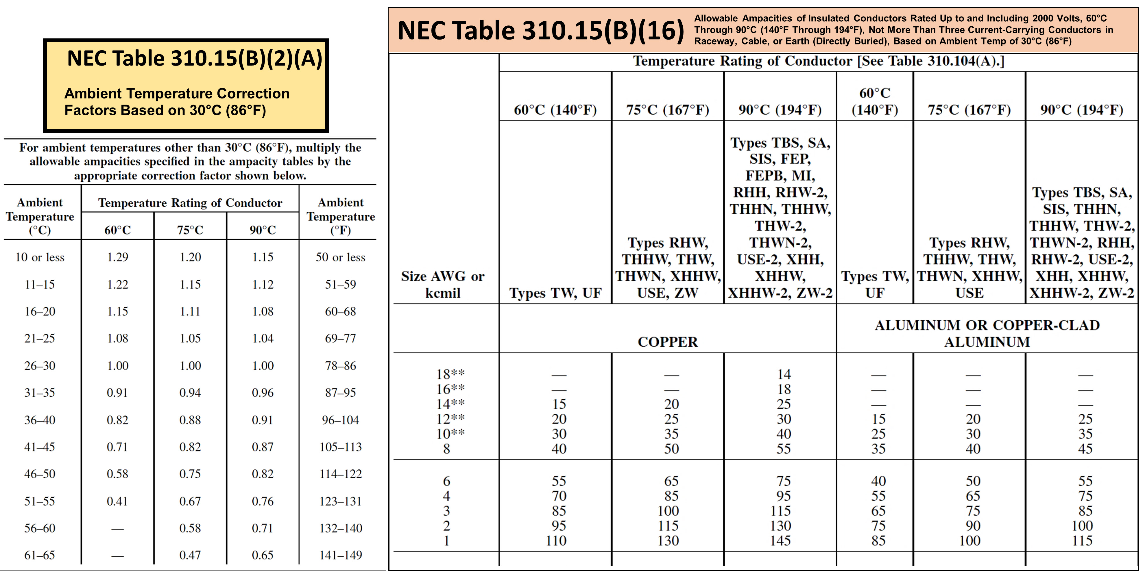
To calculate the size of a feeder cable, you need to consider several factors, including the load requirements, voltage drop, and current carrying capacity. The calculation involves determining the ampacity of the cable, which is the maximum amount of electric current it can safely carry. This is typically done using the National Electric Code (NEC) tables and formulas, which take into account factors such as the cable type, insulation, and ambient temperature.
Understanding Feeder Cable Requirements
To calculate the size of a feeder cable, you need to understand the requirements of the load it will be serving. This includes determining the total load in watts or volt-amperes, as well as the power factor and efficiency of the load. You also need to consider the distance the cable will be run, as this will affect the voltage drop. The calculation involves determining the minimum cable size required to meet the load requirements while also ensuring safe and efficient operation.
- Determine the total load in watts or volt-amperes.
- Calculate the required ampacity of the cable based on the load requirements.
- Consider the distance the cable will be run and the voltage drop that will occur.
Calculating Voltage Drop
Voltage drop is a critical factor in calculating the size of a feeder cable. The voltage drop occurs due to the resistance of the cable, and it can cause a reduction in the voltage available to the load. To calculate the voltage drop, you need to use the formula: VD = (2 x L x I x R) / 1000, where VD is the voltage drop, L is the length of the cable, I is the current, and R is the resistance.
- Determine the length of the cable in feet.
- Calculate the current in amperes that will be flowing through the cable.
- Use the formula to calculate the voltage drop.
Determining Cable Ampacity
The ampacity of a feeder cable is the maximum amount of electric current it can safely carry. To determine the ampacity, you need to use the NEC tables, which provide the ampacity for different cable types and sizes. You also need to consider the ambient temperature and the number of conductors in the cable, as these can affect the ampacity.
- Determine the cable type and size.
- Use the NEC tables to determine the ampacity.
- Consider the ambient temperature and number of conductors.
Considering Cable Insulation and Type
The insulation and type of a feeder cable can affect its ampacity and voltage drop. For example, thermoplastic insulation has a higher temperature rating than thermoset insulation, which can affect the ampacity. Additionally, copper conductors have a higher conductivity than aluminum conductors, which can reduce the voltage drop.
- Determine the insulation type and its temperature rating.
- Consider the conductor material and its conductivity.
- Use the NEC tables to determine the ampacity based on the cable type and insulation.
Using NEC Tables and Formulas
The NEC provides tables and formulas to help calculate the size of a feeder cable. The tables provide the ampacity for different cable types and sizes, while the formulas can be used to calculate the voltage drop and required ampacity. To use the tables and formulas, you need to determine the cable type and size, as well as the load requirements and distance the cable will be run.
- Determine the cable type and size.
- Use the NEC tables to determine the ampacity.
- Use the NEC formulas to calculate the voltage drop and required ampacity.
What is the 40 percent conduit fill rule?

The 40 percent conduit fill rule is a regulation that governs the amount of electrical conductors that can be installed in a conduit. This rule is designed to prevent overheating and ensure safe installation of electrical systems. The rule states that the total cross-sectional area of all conductors in a conduit cannot exceed 40% of the conduit's internal cross-sectional area.
Introduction to the 40 Percent Conduit Fill Rule
The 40 percent conduit fill rule is an essential part of electrical installation standards. To comply with this rule, electricians must calculate the total cross-sectional area of all conductors and compare it to the conduit's internal cross-sectional area. Here are some key points to consider:
- The rule applies to all types of conduits, including rigid and flexible conduits.
- The cross-sectional area of each conductor is calculated based on its diameter and insulation type.
- The conduit's internal cross-sectional area is calculated based on its diameter and wall thickness.
Purpose of the 40 Percent Conduit Fill Rule
The primary purpose of the 40 percent conduit fill rule is to prevent overheating and electrical fires. When conduits are overcrowded, they can cause conductors to overheat, leading to insulation damage and short circuits. Here are some benefits of following this rule:
- Reduced risk of electrical fires and shocks.
- Improved safety for electricians and building occupants.
- Increased system reliability and efficiency.
Calculating Conduit Fill
To calculate conduit fill, electricians must use a formula that takes into account the cross-sectional area of each conductor and the conduit's internal cross-sectional area. The formula is: Conduit Fill (%) = (Total Conductor Area / Conduit Internal Area) x 100. Here are some steps to follow:
- Determine the diameter and insulation type of each conductor.
- Calculate the cross-sectional area of each conductor.
- Calculate the conduit's internal cross-sectional area.
Consequences of Non-Compliance
Failing to comply with the 40 percent conduit fill rule can have serious consequences, including electrical fires, shocks, and system failures. Here are some risks associated with non-compliance:
- Increased risk of electrical fires and shocks.
- Reduced system reliability and efficiency.
- Potential for electrical code violations and fines.
Best Practices for Conduit Fill
To ensure compliance with the 40 percent conduit fill rule, electricians should follow best practices, including proper conduit sizing and conductor selection. Here are some tips to consider:
- Use conduit sizing tables to determine the minimum conduit size required.
- Select conductors with the correct insulation type and diameter.
- Verify conduit fill calculations to ensure compliance with the 40 percent rule.
How many cables can fit in a 1 inch conduit?
The number of cables that can fit in a 1-inch conduit depends on several factors, including the size and type of the cables, as well as the conduit fill requirements. Generally, a 1-inch conduit can accommodate multiple cables, but the exact number depends on the specific cable sizes and types being used. To determine the maximum number of cables that can fit in a 1-inch conduit, it is essential to consult the National Electric Code (NEC) tables and calculations.
Understanding Conduit Fill Requirements
The NEC provides guidelines for conduit fill requirements, which dictate the maximum number of cables that can be installed in a conduit. The conduit fill requirements are based on the cable size and type, as well as the conduit size. To calculate the maximum number of cables that can fit in a 1-inch conduit, the following steps can be taken:
- Determine the cable size and type being used
- Consult the NEC tables to determine the conduit fill requirements
- Calculate the maximum number of cables that can fit in the conduit based on the conduit size and cable size
Factors Affecting Cable Capacity
Several factors can affect the number of cables that can fit in a 1-inch conduit, including the cable insulation, cable shielding, and conduit material. For example, thicker insulation or shielding can reduce the number of cables that can fit in the conduit, while larger conduit sizes can accommodate more cables. Additionally, the conduit material can also impact the cable capacity, with metallic conduits generally allowing for more cables than non-metallic conduits.
- Cable insulation can affect the cable diameter and reduce the number of cables that can fit in the conduit
- Cable shielding can also increase the cable diameter and reduce the cable capacity
- Conduit material can impact the cable capacity, with metallic conduits generally allowing for more cables
Cable Size and Type Considerations
The cable size and type are critical factors in determining the number of cables that can fit in a 1-inch conduit. Larger cables or cables with thicker insulation can reduce the number of cables that can fit in the conduit, while smaller cables or cables with thinner insulation can allow for more cables. Additionally, the cable type, such as power cables or control cables, can also impact the cable capacity.
- Larger cables can reduce the number of cables that can fit in the conduit
- Cables with thicker insulation can also reduce the cable capacity
- Smaller cables or cables with thinner insulation can allow for more cables
Conduit Sizing and Selection
Proper conduit sizing and selection are essential to ensure that the conduit can accommodate the required number of cables. The conduit size should be selected based on the cable size and type, as well as the conduit fill requirements. Additionally, the conduit material and conduit type should also be considered when selecting a conduit.
- Conduit size should be selected based on the cable size and type
- Conduit material and conduit type should also be considered when selecting a conduit
- Conduit fill requirements should be consulted to ensure the conduit can accommodate the required number of cables
Calculating Maximum Cable Capacity
To calculate the maximum number of cables that can fit in a 1-inch conduit, the cable size and type should be determined, and the conduit fill requirements should be consulted. The NEC tables can be used to determine the maximum number of cables that can fit in the conduit based on the cable size and conduit size. Additionally, cable management tools and software can also be used to calculate the maximum cable capacity and ensure compliance with the NEC requirements.
- Cable size and type should be determined to calculate the maximum cable capacity
- Conduit fill requirements should be consulted to ensure compliance with the NEC
- Cable management tools and software can be used to calculate the maximum cable capacity and ensure compliance
What is the ratio of cable to conduit?
The ratio of cable to conduit is a critical factor in determining the overall efficiency and safety of an electrical system. The National Electric Code (NEC) provides guidelines for the maximum cable fill in a conduit, which is typically 40% for power cables and 50% for control cables. This means that the conduit should not be filled more than 40% or 50% with cables, depending on the type of cable being used.
Understanding the Importance of Cable to Conduit Ratio
The cable to conduit ratio is important because it affects the heat dissipation and current carrying capacity of the cables. If the conduit is overfilled with cables, it can lead to overheating, which can cause cable damage and even fires. To ensure safe and efficient operation, it is essential to maintain the recommended cable to conduit ratio.
- The cable to conduit ratio affects the ampacity of the cables.
- Conduit fill rates are critical in determining the cable size and type.
- Cable management is essential to maintain the recommended cable to conduit ratio.
Cable Fill Rates and Conduit Sizing
Cable fill rates and conduit sizing are closely related, as the conduit size determines the maximum cable fill rate. The NEC provides tables and formulas to help determine the conduit size based on the cable size and type.
- Conduit sizing is critical to ensure safe and efficient operation.
- Cable fill rates must be calculated carefully to avoid overfilling.
- Conduit sizing tables and formulas are available in the NEC.
Factors Affecting Cable to Conduit Ratio
Several factors affect the cable to conduit ratio, including the type of cable, conduit material, and ambient temperature. For example, high-temperature cables may require a lower cable to conduit ratio to ensure safe operation.
- Cable type affects the cable to conduit ratio.
- Conduit material affects the cable to conduit ratio.
- Ambient temperature affects the cable to conduit ratio.
Calculating Cable to Conduit Ratio
Calculating the cable to conduit ratio involves determining the cable area and conduit area, and then applying the recommended cable fill rate. This calculation can be complex, especially for large conduit systems.
- Cable area must be calculated carefully.
- Conduit area must be calculated carefully.
- Cable fill rates must be applied correctly.
Best Practices for Maintaining Cable to Conduit Ratio
To maintain the recommended cable to conduit ratio, it is essential to follow best practices, such as proper cable management, regular inspections, and maintenance. This includes ensuring that cables are properly secured and labeled, and that conduits are clean and dry.
- Cable management is essential to maintain the recommended cable to conduit ratio.
- Regular inspections are critical to identify potential issues.
- Maintenance is essential to ensure safe and efficient operation.
Frequently Asked Questions (FAQs)
What is the E-Feeder Cable and Conduit Size Design Calculator and how does it work?
The E-Feeder Cable and Conduit Size Design Calculator is a powerful tool designed to help electrical engineers and designers determine the optimal cable size and conduit size for their electrical feeder systems. This calculator uses complex algorithms and industry standards to ensure that the selected cable and conduit sizes meet the required ampacity and voltage drop specifications. By inputting project-specific parameters, such as load calculations, distance, and ambient temperature, users can quickly and accurately determine the required cable and conduit sizes, saving time and reducing the risk of errors. The calculator also takes into account National Electric Code (NEC) requirements and other industry standards, making it a reliable and comprehensive tool for electrical system design.
How do I use the E-Feeder Cable and Conduit Size Design Calculator to determine the optimal cable size for my project?
To use the E-Feeder Cable and Conduit Size Design Calculator, users must first gather project-specific information, including load calculations, distance, ambient temperature, and conductor material. This information is then entered into the calculator, which uses proprietary algorithms to determine the required cable size based on ampacity and voltage drop specifications. The calculator also allows users to select from a variety of cable types, including copper and aluminum, and conduit materials, such as PVC and galvanized steel. By following the step-by-step input process and selecting the appropriate options, users can quickly and accurately determine the optimal cable size for their project, ensuring safe and efficient operation of the electrical system. Additionally, the calculator provides detailed reports and charts, making it easy to document and verify the results.
What are the benefits of using the E-Feeder Cable and Conduit Size Design Calculator for electrical system design?
The E-Feeder Cable and Conduit Size Design Calculator offers numerous benefits for electrical system design, including increased accuracy, reduced design time, and improved safety. By using advanced algorithms and industry standards, the calculator ensures that the selected cable and conduit sizes meet the required ampacity and voltage drop specifications, reducing the risk of overheating, short circuits, and other electrical hazards. Additionally, the calculator helps users to optimize their electrical system design, reducing material costs and energy consumption. The calculator also provides detailed documentation, making it easy to verify and validate the results, and to meet regulatory requirements. Overall, the E-Feeder Cable and Conduit Size Design Calculator is a valuable tool for any electrical engineer or designer looking to create safe, efficient, and cost-effective electrical systems.
Can the E-Feeder Cable and Conduit Size Design Calculator be used for both residential and commercial electrical system design?
Yes, the E-Feeder Cable and Conduit Size Design Calculator can be used for both residential and commercial electrical system design. The calculator is flexible and versatile, allowing users to input project-specific parameters and select from a variety of cable types and conduit materials. Whether you are designing an electrical system for a single-family home or a large commercial building, the calculator can help you to determine the optimal cable size and conduit size to ensure safe and efficient operation. The calculator also takes into account National Electric Code (NEC) requirements and other industry standards, making it a reliable and comprehensive tool for electrical system design. Additionally, the calculator provides detailed reports and charts, making it easy to document and verify the results, and to meet regulatory requirements for both residential and commercial projects.
Deja una respuesta
Entradas Relacionadas