
Curved I-Beam Stress Formulas and Calculator

The curved I-beam is a complex structural element that requires precise calculations to determine its stress and load-bearing capacity. Traditional straight beam formulas are inadequate for curved beams, as the curvature introduces additional stresses and complexities. This article provides a comprehensive overview of curved I-beam stress formulas and offers a calculator to simplify the calculation process. The formulas and calculator presented here enable engineers to accurately determine the stresses and loads on curved I-beams, ensuring safe and efficient design of structures that incorporate these elements, such as bridges, arches, and other curved frameworks. Accurate calculations are crucial.
- Understanding Curved I-Beam Stress Formulas and Calculator
- What is the name formula for stresses in a curved beam?
- How to calculate stress in an I-beam?
- What is the stress distribution of a curved beam?
- What is the formula for beam curvature?
-
Frequently Asked Questions (FAQs)
- What are the Curved I-Beam Stress Formulas and how are they used in engineering applications?
- How do the Curved I-Beam Stress Formulas differ from those used for straight I-beams?
- What are some common applications of the Curved I-Beam Stress Formulas in engineering practice?
- How can the Curved I-Beam Stress Formulas and Calculator be used to optimize the design of curved I-beams?
Understanding Curved I-Beam Stress Formulas and Calculator
The calculation of stress in curved I-beams is a complex task that requires a deep understanding of structural mechanics and mathematics. Curved I-beams are commonly used in various engineering applications, including bridges, buildings, and other structures. The curved shape of the beam introduces additional stresses and loads that must be carefully considered to ensure the structural integrity of the beam. In this context, the use of formulas and calculators becomes essential to determine the stress and strain on the beam.
Introduction to Curved I-Beam Stress Formulas
The stress formulas for curved I-beams are based on the theory of elasticity and beam theory. These formulas take into account the curvature of the beam, as well as the applied loads and boundary conditions. The most commonly used formulas for calculating stress in curved I-beams are the Vlasov formula and the Timoshenko formula. These formulas provide a mathematical model for predicting the stress and strain on the beam.
Key Factors Affecting Curved I-Beam Stress
Several factors can affect the stress on a curved I-beam, including the radius of curvature, beam length, cross-sectional area, and applied loads. The radius of curvature is a critical factor, as it determines the degree of curvature of the beam. The beam length and cross-sectional area also play important roles, as they affect the stiffness and strength of the beam. Additionally, the applied loads, such as bending moments and torque, can significantly impact the stress on the beam.
Curved I-Beam Stress Calculator
A curved I-beam stress calculator is a software tool that uses algorithms and formulas to calculate the stress on a curved I-beam. These calculators can be used to analyze and design curved I-beams for various applications. The calculator typically requires input parameters such as the beam geometry, material properties, and applied loads. The calculator then uses these inputs to calculate the stress and strain on the beam, providing valuable insights for engineering design and analysis.
| Parameter | Unit | Description |
|---|---|---|
| Radius of Curvature | m | The radius of curvature of the beam |
| Beam Length | m | The length of the beam |
| Cross-Sectional Area | m^2 | The cross-sectional area of the beam |
| Applied Loads | N | The applied loads on the beam, such as bending moments and torque |
| Material Properties | - | The material properties of the beam, such as Young's modulus and Poisson's ratio |
Applications of Curved I-Beam Stress Formulas and Calculator
The curved I-beam stress formulas and calculator have a wide range of applications in various fields, including civil engineering, mechanical engineering, and aerospace engineering. These formulas and calculators can be used to design and analyze curved I-beams for bridges, buildings, aircraft, and other structures. Additionally, they can be used to optimize the design of curved I-beams, reducing weight and cost while maintaining structural integrity.
Limitations and Assumptions of Curved I-Beam Stress Formulas and Calculator
The curved I-beam stress formulas and calculator are based on simplifying assumptions and limitations, such as the theory of elasticity and beam theory. These assumptions and limitations can affect the accuracy and validity of the results. Additionally, the calculator may not account for non-linear effects, such as large deformations and material non-linearity. Therefore, the results should be interpreted and validated with caution, taking into account the limitations and assumptions of the formulas and calculator.
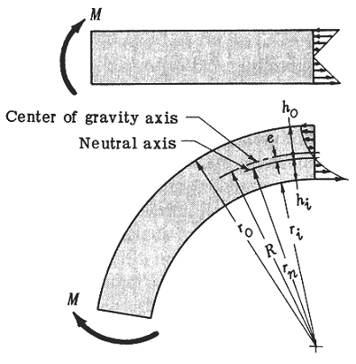
What is the name formula for stresses in a curved beam?
The name formula for stresses in a curved beam is known as the Winkler-Bach formula or the curved beam formula. This formula is used to calculate the stress distribution in a curved beam under bending and tension loads. The formula takes into account the curvature of the beam and the distance from the neutral axis to the point of interest.
Introduction to Curved Beams
Curved beams are structural elements that are used in a wide range of applications, including bridges, pipes, and machinery. These beams are subjected to various types of loads, including bending, tension, and compression. The stress distribution in curved beams is more complex than in straight beams due to the curvature effect. Some key points to consider when dealing with curved beams include:
- Curvature: The curvature of the beam affects the stress distribution and must be taken into account when calculating stresses.
- Distance: The distance from the neutral axis to the point of interest is critical in determining the stress at that point.
- Load type: The type of load applied to the beam, such as bending or tension, affects the stress distribution.
Derivation of the Winkler-Bach Formula
The Winkler-Bach formula is derived from the equilibrium equations and the stress-strain relationship. The formula is based on the assumption that the beam is homogeneous and isotropic, and that the cross-sectional area is constant. The derivation involves integrating the stress distribution over the cross-sectional area to obtain the resultant force and moment. Some key steps in the derivation include:
- Equilibrium equations: The equilibrium equations are used to balance the forces and moments acting on the beam.
- Stress-strain relationship: The stress-strain relationship is used to relate the stress to the strain.
- Integration: The stress distribution is integrated over the cross-sectional area to obtain the resultant force and moment.
Applications of the Winkler-Bach Formula
The Winkler-Bach formula has a wide range of applications in engineering and design. It is used to calculate the stress distribution in curved beams under various types of loads. Some examples of applications include:
- Bridge design: The formula is used to calculate the stress distribution in curved bridge beams.
- Pipe design: The formula is used to calculate the stress distribution in curved pipes.
- Machinery design: The formula is used to calculate the stress distribution in curved machinery components.
Limitations of the Winkler-Bach Formula
The Winkler-Bach formula has some limitations that must be considered when applying it to real-world problems. Some of these limitations include:
- Assumptions: The formula is based on assumptions such as homogeneity and isotropy, which may not always be valid.
- Simplifications: The formula involves simplifications such as neglecting shear and torsion effects.
- Complexity: The formula can be complex and difficult to apply to complex geometries.
Extensions and Modifications of the Winkler-Bach Formula
The Winkler-Bach formula has been extended and modified to account for various effects such as shear, torsion, and non-linear behavior. Some of these extensions and modifications include:
- Shear effects: The formula has been modified to include shear effects, which can be significant in thin-walled structures.
- Torsion effects: The formula has been modified to include torsion effects, which can be significant in twisted structures.
- Non-linear behavior: The formula has been modified to account for non-linear behavior, which can occur under large deformations.
How to calculate stress in an I-beam?
To calculate stress in an I-beam, you need to consider the forces acting on the beam, including the weight of the beam itself, as well as any external loads. The calculation involves determining the bending moment and shear force at different points along the beam. This requires a thorough understanding of statics and strength of materials.
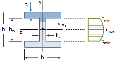
Understanding I-Beam Geometry
The geometry of an I-beam is crucial in calculating stress. The I-beam consists of two flanges connected by a web, and the dimensions of these components affect the moment of inertia and section modulus of the beam. To calculate stress, you need to determine the area and centroid of the cross-section, as well as the distance from the neutral axis to the extreme fibers.
- Calculate the area of the flanges and web
- Determine the centroid of the cross-section
- Find the moment of inertia and section modulus of the beam
Calculating Bending Moment and Shear Force
The bending moment and shear force diagrams are essential in determining the stress distribution along the beam. You can calculate these diagrams using the equations of equilibrium and the load applied to the beam. The bending moment is calculated by integrating the shear force diagram, and the shear force is calculated by differentiating the load function.
- Determine the load function and boundary conditions
- Calculate the shear force diagram using the equations of equilibrium
- Integrate the shear force diagram to find the bending moment diagram
Applying Stress Formulas
Once you have the bending moment and shear force diagrams, you can apply the stress formulas to calculate the normal stress and shear stress at different points along the beam. The flexure formula is used to calculate the normal stress due to bending, and the shear formula is used to calculate the shear stress due to shear force.
- Apply the flexure formula to calculate normal stress
- Apply the shear formula to calculate shear stress
- Combine the normal stress and shear stress to find the principal stress
Considering Material Properties
The calculation of stress in an I-beam also requires consideration of the material properties, including the elastic modulus, yield strength, and ultimate strength. These properties affect the stress-strain behavior of the material and determine the failure of the beam.
- Determine the elastic modulus and poisson's ratio of the material
- Find the yield strength and ultimate strength of the material
- Check for failure using the stress calculated and the material properties
Using Numerical Methods
In practice, the calculation of stress in an I-beam can be complex and may require numerical methods, such as the finite element method. These methods involve discretizing the beam into elements and solving the equations of equilibrium using numerical techniques.
- Discretize the beam into elements using a mesh
- Apply the boundary conditions and load to the elements
- Solve the equations of equilibrium using a numerical solver
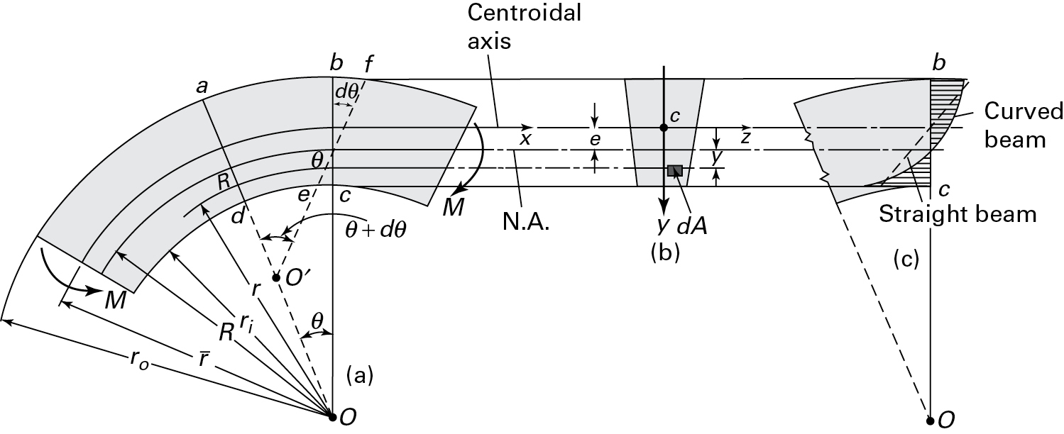
What is the stress distribution of a curved beam?
The stress distribution of a curved beam is a complex phenomenon that depends on various factors, including the beam's geometry, material properties, and loading conditions. Unlike straight beams, curved beams experience a non-uniform stress distribution due to the curvature, which affects the beam's behavior under load.
Introduction to Curved Beam Stress Distribution
The stress distribution in a curved beam is influenced by the curvature of the beam, which causes the stress to vary across the beam's cross-section. This variation in stress is due to the normal stresses that arise from the bending moment and the tangential stresses that result from the torsional moment. The stress distribution can be analyzed using the theory of elasticity, which provides a mathematical framework for understanding the stress and strain behavior in curved beams.
- The curvature of the beam affects the stress distribution, with higher curvatures resulting in greater stress variations.
- The material properties, such as the Young's modulus and Poisson's ratio, influence the stress distribution and the beam's overall behavior.
- The loading conditions, including the type and magnitude of the load, also impact the stress distribution in curved beams.
Types of Stresses in Curved Beams
Curved beams experience various types of stresses, including normal stresses, tangential stresses, and shear stresses. The normal stresses arise from the bending moment, while the tangential stresses result from the torsional moment. The shear stresses occur due to the shear force and can be significant in curved beams with high curvatures.
- The normal stresses are the primary stresses in curved beams, causing the beam to bend and deform.
- The tangential stresses are secondary stresses that arise from the torsional moment, affecting the beam's behavior under load.
- The shear stresses can be significant in curved beams, particularly those with high curvatures or subjected to torque.
Factors Influencing Stress Distribution in Curved Beams
Several factors influence the stress distribution in curved beams, including the beam geometry, material properties, and loading conditions. The beam geometry, such as the radius of curvature and cross-sectional shape, affects the stress distribution. The material properties, including the Young's modulus and Poisson's ratio, also impact the stress distribution.
- The beam geometry plays a significant role in determining the stress distribution, with different geometries resulting in varied stress patterns.
- The material properties influence the stress distribution, with different materials exhibiting unique stress-strain behaviors.
- The loading conditions, including the type and magnitude of the load, impact the stress distribution and the beam's overall behavior.
Methods for Analyzing Stress Distribution in Curved Beams
Various methods can be employed to analyze the stress distribution in curved beams, including the theory of elasticity, finite element method, and experimental methods. The theory of elasticity provides a mathematical framework for understanding the stress and strain behavior in curved beams, while the finite element method offers a numerical approach for analyzing complex stress distributions.
- The theory of elasticity provides a fundamental understanding of the stress distribution in curved beams, allowing for the development of mathematical models.
- The finite element method offers a powerful tool for analyzing complex stress distributions, enabling the simulation of various loading conditions and beam geometries.
- The experimental methods, such as strain gauge measurements, provide a means for validating stress distribution predictions and understanding the behavior of curved beams under load.
Applications of Curved Beam Stress Distribution Analysis
The analysis of stress distribution in curved beams has numerous applications in various fields, including civil engineering, mechanical engineering, and aerospace engineering. The understanding of stress distribution is crucial for the design and analysis of curved beam structures, such as bridges, pipes, and aircraft components.
- The stress distribution analysis is essential for the design of curved beam structures, ensuring the safety and reliability of the structure under various loading conditions.
- The analysis of stress distribution helps to optimize the design of curved beam structures, minimizing weight and material usage while maintaining structural integrity.
- The understanding of stress distribution is critical for the maintenance and repair of curved beam structures, allowing for the identification of potential failure modes and the implementation of preventive measures.
What is the formula for beam curvature?

The formula for beam curvature is given by the equation: κ = M / (EI), where κ is the curvature, M is the bending moment, E is the modulus of elasticity, and I is the moment of inertia. This formula is used to calculate the curvature of a beam under a given load and is a fundamental concept in structural analysis.
Understanding Beam Curvature
Beam curvature is an important aspect of structural engineering, as it determines the deflection and stress of a beam under various loads. The formula for beam curvature is derived from the beam theory, which assumes that the beam is a long, slender member that is subjected to bending loads. The curvature of a beam is influenced by factors such as the material properties, cross-sectional shape, and loading conditions.
- Material properties: The modulus of! elasticity (E) and the moment of inertia (I) are critical material properties that affect the curvature of a beam.
- Cross-sectional shape: The shape of the beam's cross-section, such as a rectangular or circular shape, influences the moment of inertia and therefore the curvature.
- Loading conditions: The type and magnitude of the load, such as a point load or a distributed load, affect the bending moment and curvature of the beam.
Applications of Beam Curvature
The formula for beam curvature has numerous applications in civil engineering, mechanical engineering, and aerospace engineering. It is used to design and analyze beams, columns, and other structural members that are subjected to bending loads. The curvature of a beam is also important in the design of bridges, buildings, and aircraft.
- Bridge design: The curvature of beams is critical in the design of bridges, as it affects the structural integrity and safety of the bridge.
- Building design: The curvature of beams is important in the design of buildings, as it influences the load-carrying capacity and stability of the structure.
- Aircraft design: The curvature of beams is also important in the design of aircraft, as it affects the structural integrity and performance of the aircraft.
Factors Affecting Beam Curvature
Several factors affect the curvature of a beam, including the bending moment, material properties, and cross-sectional shape. The bending moment is the primary factor that affects the curvature of a beam, as it causes the beam to deflect and change shape. The material properties, such as the modulus of elasticity and Poisson's ratio, also influence the curvature of a beam.
- Bending moment: The bending moment is the primary factor that affects the curvature of a beam, as it causes the beam to deflect and change shape.
- Material properties: The material properties, such as the modulus of elasticity and Poisson's ratio, influence the curvature of a beam.
- Cross-sectional shape: The cross-sectional shape of the beam, such as a rectangular or circular shape, affects the moment of inertia and therefore the curvature.
Calculating Beam Curvature
The calculation of beam curvature involves determining the bending moment and moment of inertia of the beam. The bending moment is calculated using the load and support conditions of the beam, while the moment of inertia is calculated using the cross-sectional shape and material properties. The curvature is then calculated using the formula: κ = M / (EI).
- Determine the bending moment: The bending moment is calculated using the load and support conditions of the beam.
- Calculate the moment of inertia: The moment of inertia is calculated using the cross-sectional shape and material properties.
- Calculate the curvature: The curvature is calculated using the formula: κ = M / (EI).
Importance of Beam Curvature
The beam curvature is a critical parameter in structural analysis, as it determines the deflection and stress of a beam under various loads. The curvature of a beam is also important in the design of beams, columns, and other structural members, as it affects the load-carrying capacity and stability of the structure. The calculation of beam curvature is therefore essential in ensuring the safety and integrity of structures.
- Deflection: The curvature of a beam determines the deflection of the beam under various loads.
- Stress: The curvature of a beam also determines the stress of the beam under various loads.
- Load-carrying capacity: The curvature of a beam affects the load-carrying capacity and stability of the structure.
Frequently Asked Questions (FAQs)
What are the Curved I-Beam Stress Formulas and how are they used in engineering applications?
The Curved I-Beam Stress Formulas are a set of mathematical equations used to calculate the stress and strain on curved I-beams, which are commonly used in construction, bridge building, and other civil engineering applications. These formulas take into account the curvature of the beam, as well as the loading conditions, to determine the maximum stress and minimum stress points along the beam. By using these formulas, engineers can design and analyze curved I-beams that are stronger, lighter, and more efficient. The Curved I-Beam Stress Formulas are typically used in conjunction with other engineering tools, such as finite element analysis and computer-aided design, to ensure that the curved I-beam is designed to withstand the loads and stresses it will experience in service.
How do the Curved I-Beam Stress Formulas differ from those used for straight I-beams?
The Curved I-Beam Stress Formulas differ from those used for straight I-beams in that they take into account the curvature of the beam, which introduces additional stresses and loads that must be considered. In particular, the curvature of the beam can cause tangential stresses and radial stresses that are not present in straight I-beams. The Curved I-Beam Stress Formulas must also account for the variation in cross-sectional area along the length of the beam, which can affect the stress distribution and load-carrying capacity of the beam. Furthermore, the boundary conditions for curved I-beams are typically more complex than those for straight I-beams, requiring a more sophisticated mathematical analysis to determine the stress and strain distribution. By using the Curved I-Beam Stress Formulas, engineers can ensure that their designs take into account these unique characteristics of curved I-beams.
What are some common applications of the Curved I-Beam Stress Formulas in engineering practice?
The Curved I-Beam Stress Formulas have a wide range of applications in engineering practice, including bridge building, highway construction, building design, and industrial equipment. For example, curved I-beams are often used in bridge construction to provide a strong and stiff structural member that can resist the loads and stresses imposed by traffic and other external forces. In building design, curved I-beams may be used to create architecturally distinctive features, such as curved roofs or vaulted ceilings. The Curved I-Beam Stress Formulas can also be used to design and analyze industrial equipment, such as cranes and hoists, that require strong and reliable structural members. By using the Curved I-Beam Stress Formulas, engineers can ensure that their designs are safe, efficient, and cost-effective.
How can the Curved I-Beam Stress Formulas and Calculator be used to optimize the design of curved I-beams?
The Curved I-Beam Stress Formulas and Calculator can be used to optimize the design of curved I-beams by allowing engineers to quickly and easily analyze and compare different design options. By using the Calculator, engineers can input different design parameters, such as the beam geometry, material properties, and loading conditions, and instantly obtain the stress and strain distribution along the beam. This allows engineers to iterate on their design, making adjustments and refinements until they achieve the optimal balance of strength, stiffness, and weight. The Curved I-Beam Stress Formulas and Calculator can also be used to investigate the effects of different design variables, such as the curvature and cross-sectional area, on the stress and strain distribution. By using these tools, engineers can create optimized designs that are stronger, lighter, and more efficient than traditional designs.
Deja una respuesta
Entradas Relacionadas