
Beam Stress Equations and Calculator Cantilevered Beam with Load at Location Between Support and Load

The calculation of beam stress is a crucial aspect of engineering design, particularly when dealing with cantilevered beams. A cantilevered beam with a load at a location between the support and the end of the beam is a common scenario in many structural applications. To determine the stress and deflection of such a beam, specific equations are used. These beam stress equations take into account the load's magnitude, its position, and the beam's properties. A calculator can simplify this process, providing accurate results for various load and beam configurations, which is essential for ensuring the structural integrity.
- Beam Stress Equations and Calculator Cantilevered Beam with Load at Location Between Support and Load
- What is the formula for a cantilever beam carrying uniformly distributed load?
- What is the bending moment formula for cantilever beam with point load at free end?
-
Frequently Asked Questions (FAQs)
- What are the key factors to consider when calculating beam stress for a cantilevered beam with a load at a location between the support and the end?
- How do beam stress equations account for the location of the load on a cantilevered beam?
- What are the limitations of using beam stress equations to calculate the stress on a cantilevered beam with a load at a location between the support and the end?
- How can a calculator be used to simplify the process of calculating beam stress for a cantilevered beam with a load at a location between the support and the end?
Beam Stress Equations and Calculator Cantilevered Beam with Load at Location Between Support and Load
The calculation of beam stress is crucial in engineering design, particularly when dealing with cantilevered beams that have a load applied at a location between the support and the end of the beam. This scenario is common in various structural applications, including building construction, bridge design, and mechanical engineering. To accurately determine the stresses and deflections in such beams, engineers use specific equations and often rely on calculators or software tools to simplify the process.
Understanding Cantilevered Beams
A cantilevered beam is a structural element that extends from a fixed support on one end and is free at the other end. When a load is applied between the support and the free end, it creates a bending moment and shear forces along the length of the beam. The beam stress equations take into account the beam's cross-sectional area, moment of inertia, and the distance from the neutral axis to calculate the stress at any point along the beam.
Beam Stress Equations
The beam stress equations are based on the principles of mechanics of materials. The flexural stress (( sigma )) in a beam can be calculated using the formula: ( sigma = frac{M cdot y}{I} ), where ( M ) is the bending moment, ( y ) is the distance from the neutral axis, and ( I ) is the moment of inertia of the beam's cross-section. For a cantilevered beam with a point load at a distance ( L ) from the fixed end, the bending moment at any point ( x ) along the beam can be calculated using the formula: ( M = P cdot x ) for ( x leq L ), where ( P ) is the applied load.
Calculator for Cantilevered Beam with Load
A calculator for a cantilevered beam with a load at a location between the support and the free end typically requires input of the beam's length, cross-sectional dimensions, material properties (such as Young's modulus), the magnitude of the load, and the distance from the support to the load. The calculator then uses the beam stress equations to compute the maximum stress, maximum deflection, and other relevant parameters. This tool is invaluable for design engineers to ensure that their beam designs can safely withstand the anticipated loads without failing due to excessive stress or deflection.
Application of Beam Stress Equations
The application of beam stress equations is not limited to simple cantilevered beams. These principles can be extended to more complex beam configurations, including simply supported beams and overhanging beams, by applying the appropriate boundary conditions and load distributions. Furthermore, the beam stress equations can be integrated into finite element analysis (FEA) software to analyze beams and other structural components under various loading conditions, providing a detailed stress analysis and deformation predictions.
Importance of Accurate Calculations
The importance of accurate calculations in beam design cannot be overstated. Incorrect assumptions or miscalculations can lead to structural failures, resulting in significant economic losses and potentially dangerous situations. Therefore, engineers must scrutinize their design calculations, ensuring that they accurately account for all loads, support conditions, and material properties. This attention to detail is crucial in delivering safe and reliable structural designs.
| Parameter | Description |
|---|---|
| Beam Length | The total length of the beam from the fixed support to the free end. |
| Load Magnitude | The amount of force applied to the beam at a specified location. |
| Distance to Load | The distance from the fixed support to the point where the load is applied. |
| Young's Modulus | A measure of the beam material's stiffness and resistance to deformation. |
| Maximum Stress | The highest stress value calculated at any point along the beam due to the applied load. |
What is the formula for a cantilever beam carrying uniformly distributed load?

The formula for a cantilever beam carrying a uniformly distributed load is given by the equation: w = (3 E I) / (L^3), where w is the load intensity, E is the modulus of elasticity, I is the moment of inertia, and L is the length of the beam. This equation is used to calculate the deflection and stress of the beam under the given load.
Deflection Calculation
The deflection of a cantilever beam under a uniformly distributed load can be calculated using the formula: δ = (w L^4) / (8 E I), where δ is the deflection, w is the load intensity, L is the length of the beam, E is the modulus of elasticity, and I is the moment of inertia. The key factors to consider when calculating the deflection are:
- Load intensity: The amount of load applied to the beam per unit length.
- Length: The distance from the fixed end to the free end of the beam.
- Modulus of elasticity: A measure of the beam's ability to resist deformation under load.
Stress Calculation
The stress of a cantilever beam under a uniformly distributed load can be calculated using the formula: σ = (w L) / (2 I), where σ is the stress, w is the load intensity, L is the length of the beam, and I is the moment of inertia. The key factors to consider when calculating the stress are:
- Load intensity: The amount of load applied to the beam per unit length.
- Length: The distance from the fixed end to the free end of the beam.
- Moment of inertia: A measure of the beam's ability to resist bending under load.
Beam Design Considerations
When designing a cantilever beam to carry a uniformly distributed load, several factors must be considered, including:
- Material selection: Choosing a material with a high modulus of elasticity and yield strength to minimize deflection and stress.
- Cross-sectional shape: Selecting a cross-sectional shape that provides a high moment of inertia to resist bending.
- Support conditions: Ensuring that the beam is properly supported at the fixed end to prevent rotation and translation.
Load Calculation
The load applied to a cantilever beam can be calculated using the formula: w = (F / L), where w is the load intensity, F is the total load, and L is the length of the beam. The key factors to consider when calculating the load are:
- Total load: The sum of all external loads applied to the beam.
- Length: The distance from the fixed end to the free end of the beam.
- Load distribution: The manner in which the load is distributed along the length of the beam.
Real-World Applications
Cantilever beams carrying uniformly distributed loads have numerous real-world applications, including:
- Building design: Cantilever beams are used in building design to provide structural support for floors and roofs.
- Bridge design: Cantilever beams are used in bridge design to provide structural support for roadways and walkways.
- Machine design: Cantilever beams are used in machine design to provide structural support for heavy equipment and machinery.
What is the bending moment formula for cantilever beam with point load at free end?
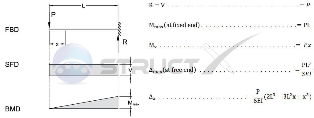
The bending moment formula for a cantilever beam with a point load at the free end is given by M = P L, where M is the bending moment, P is the point load, and L is the length of the beam. This formula is used to calculate the maximum bending moment that occurs at the fixed end of the beam.
Understanding the Bending Moment Formula
The bending moment formula is a fundamental concept in structural analysis and is used to determine the stress and strain on a beam under load. The formula M = P L is used for a cantilever beam with a point load at the free end, where the load is applied at a single point. The resulting bending moment is a measure of the torque or rotational force that causes the beam to bend. Some key points to consider when using this formula include:
- The beam must be a cantilever beam, meaning it is fixed at one end and free at the other.
- The load must be a point load, meaning it is applied at a single point rather than being distributed along the length of the beam.
- The length of the beam is a critical factor in determining the bending moment, as it directly affects the moment arm of the load.
Calculating Bending Moment for Cantilever Beams
When calculating the bending moment for a cantilever beam with a point load at the free end, it is essential to consider the boundary conditions of the beam. The fixed end of the beam must be able to resist the bending moment and shear force caused by the load. The bending moment is calculated using the formula M = P L, and the resulting stress and strain on the beam can be determined using the beam theory. Some key considerations when calculating the bending moment include:
- The material properties of the beam, such as its modulus of elasticity and yield strength.
- The geometry of the beam, including its cross-sectional area and moment of inertia.
- The load characteristics, including its magnitude and location.
Importance of Bending Moment in Structural Analysis
The bending moment is a critical factor in structural analysis, as it determines the stress and strain on a beam under load. The bending moment formula for a cantilever beam with a point load at the free end is a fundamental concept in structural engineering, and is used to design and analyze a wide range of structures, including buildings, bridges, and machinery. Some key applications of the bending moment formula include:
- Designing beams to resist bending and shear forces.
- Analyzing the stress and strain on structures under load.
- Optimizing the geometry and material properties of structures to minimize weight and cost.
Assumptions and Limitations of the Bending Moment Formula
The bending moment formula for a cantilever beam with a point load at the free end assumes a linear elastic response of the material, and neglects the effects of shear deformation and rotational inertia. The formula also assumes that the load is applied at a single point, and that the beam is prismatic, meaning it has a constant cross-sectional area along its length. Some key limitations of the formula include:
- Non-linear material behavior, such as plasticity or creep.
- Dynamic loading, such as impact or vibration.
- Non-uniform beam geometry, such as tapered or curved beams.
Real-World Applications of the Bending Moment Formula
The bending moment formula for a cantilever beam with a point load at the free end has a wide range of real-world applications, including the design and analysis of structures such as buildings, bridges, and machinery. The formula is also used in the design of mechanical components, such as shafts, beams, and frames. Some key applications of the formula include:
- Civil engineering, including the design of bridges, highways, and buildings.
- Mechanical engineering, including the design of machinery, mechanisms, and robotics.
- Aerospace engineering, including the design of aircraft, spacecraft, and missiles.
Frequently Asked Questions (FAQs)
What are the key factors to consider when calculating beam stress for a cantilevered beam with a load at a location between the support and the end?
When calculating beam stress for a cantilevered beam with a load at a location between the support and the end, there are several key factors to consider. The first factor is the length of the beam, as this will affect the moment and shear forces that are applied to the beam. The load itself is also a critical factor, as it will determine the magnitude of the forces that are applied to the beam. Additionally, the location of the load relative to the support is important, as this will affect the distribution of stresses throughout the beam. The material properties of the beam, such as its elastic modulus and yield strength, are also important considerations, as they will affect the behavior of the beam under load. By considering these factors, engineers can use beam stress equations to calculate the stresses and strains that occur in the beam, and ensure that it is designed to withstand the applied loads.
How do beam stress equations account for the location of the load on a cantilevered beam?
Beam stress equations account for the location of the load on a cantilevered beam by incorporating the distance from the support to the load into the calculations. This distance is used to calculate the moment and shear forces that are applied to the beam, which are then used to calculate the stresses and strains that occur in the beam. The beam stress equations take into account the fact that the stresses and strains will vary along the length of the beam, with the highest stresses typically occurring at the support and decreasing as you move towards the end of the beam. By using the location of the load as an input to the beam stress equations, engineers can accurately calculate the stresses and strains that occur in the beam, and ensure that it is designed to withstand the applied loads. The beam stress equations can be used to calculate a variety of stress and strain values, including the maximum bending stress, maximum shear stress, and maximum deflection.
What are the limitations of using beam stress equations to calculate the stress on a cantilevered beam with a load at a location between the support and the end?
There are several limitations to using beam stress equations to calculate the stress on a cantilevered beam with a load at a location between the support and the end. One of the main limitations is that the equations assume a simple beam with a uniform cross-section, which may not be the case in real-world applications. Additionally, the equations assume that the load is applied in a static manner, which may not be the case if the load is dynamic or oscillating. The equations also assume that the material is elastic and isotropic, which may not be the case if the material is nonlinear or anisotropic. Furthermore, the equations do not take into account other factors that can affect the stress on the beam, such as temperature, corrosion, or fatigue. As a result, the beam stress equations should be used with caution and in conjunction with other analysis tools, such as finite element analysis, to ensure that the beam is designed to withstand the applied loads.
How can a calculator be used to simplify the process of calculating beam stress for a cantilevered beam with a load at a location between the support and the end?
A calculator can be used to simplify the process of calculating beam stress for a cantilevered beam with a load at a location between the support and the end by automating the calculations and reducing the risk of human error. The calculator can be programmed with the beam stress equations and can take into account the input parameters, such as the length of the beam, the load, and the location of the load. The calculator can then rapidly calculate the stresses and strains that occur in the beam, and display the results in a clear and concise manner. This can save engineers a significant amount of time and effort, and can help to ensure that the beam is designed to withstand the applied loads. Additionally, the calculator can be used to iterate on the design, by adjusting the input parameters and recalculating the stresses and strains, until the optimal design is achieved. Overall, a calculator can be a powerful tool for calculating beam stress, and can help to streamline the design process.
Deja una respuesta
Entradas Relacionadas