
Beam Deflection Calculator for a Beam supported One End, One End, Cantilevered at Defined Location and Distributed Load Between Supports

The Beam Deflection Calculator is a valuable tool for engineers and designers, enabling them to calculate the deflection of a beam supported at one end and cantilevered at a defined location, with a distributed load between supports. This calculator takes into account various parameters such as beam length, load intensity, and Young's modulus to provide accurate results. By using this calculator, users can determine the maximum deflection and other critical factors, ensuring the structural integrity and safety of their designs. It is a reliable and efficient solution for beam deflection calculations. The calculator is easy to use.
- Beam Deflection Calculator for a Beam Supported One End, One End, Cantilevered at Defined Location and Distributed Load Between Supports
- How do you calculate beam deflection?
- What is a cantilever beam supported at one end?
- What is the EI formula for deflection?
-
Frequently Asked Questions (FAQs)
- What is the purpose of the Beam Deflection Calculator for a beam supported at one end and cantilevered at a defined location with a distributed load between supports?
- How does the Beam Deflection Calculator handle the distributed load between supports?
- What are the key parameters that need to be input into the Beam Deflection Calculator?
- What are the limitations and assumptions of the Beam Deflection Calculator?
Beam Deflection Calculator for a Beam Supported One End, One End, Cantilevered at Defined Location and Distributed Load Between Supports
The Beam Deflection Calculator is a tool used to calculate the deflection of a beam under various load conditions. In this case, we are dealing with a beam that is supported at one end, cantilevered at a defined location, and has a distributed load between the supports. This calculator is essential in the field of engineering and architecture to ensure that the beam can withstand the loads and stresses applied to it.
Introduction to Beam Deflection Calculator
The Beam Deflection Calculator is a mathematical model that uses the beam theory to calculate the deflection of a beam under different load conditions. The calculator takes into account the length of the beam, the material properties, and the load conditions to calculate the deflection. The calculator is useful for engineers and architects to design and analyze beams in various structures such as buildings, bridges, and roads.
Beam Supported One End, One End, Cantilevered at Defined Location
When a beam is supported at one end and cantilevered at a defined location, it is subject to a combination of loads including point loads, uniformly distributed loads, and moments. The Beam Deflection Calculator can handle these complex load conditions and calculate the deflection of the beam. The calculator uses the boundary conditions of the beam, such as the support conditions and the cantilever location, to determine the deflection.
Distributed Load Between Supports
A distributed load is a load that is spread out over a length of the beam. The Beam Deflection Calculator can handle distributed loads between the supports and calculate the deflection of the beam. The calculator uses the load intensity and the length of the load to calculate the deflection. The calculator can also handle multiple loads and load combinations.
Calculator Input Parameters
The Beam Deflection Calculator requires several input parameters to calculate the deflection of the beam! The input parameters include:
| Parameter | Description |
|---|---|
| Length | The length of the beam |
| Material | The material properties of the beam |
| Load | The load conditions applied to the beam |
| Support | The support conditions of the beam |
| Cantilever | The cantilever location and length |
These input parameters are used to calculate the deflection of the beam.
Calculator Output Results
The Beam Deflection Calculator provides several output results,! including the deflection of the beam, the bending moment, and the shear force. The calculator also provides a graphical representation of the deflection and the load conditions. The output results are useful for engineers and architects to analyze and design beams in various structures. The calculator can also provide warnings and errors if the input parameters are not valid or if the calculator is unable to calculate the deflection.
How do you calculate beam deflection?
To calculate beam deflection, you need to consider the beam's geometry, material properties, and loading conditions. The calculation involves integrating the moment and shear equations to find the deflection and slope of the beam at any point. This can be done using various methods, including the method of superposition, moments and forces, and energy methods.
Understanding Beam Deflection Theory
Beam deflection theory is based on the Euler-Bernoulli beam equation, which relates the deflection of the beam to the applied loads and beam properties. To calculate beam deflection, you need to understand the boundary conditions and loading conditions of the beam. The deflection of the beam can be calculated using the following steps:
- Define the beam geometry and material properties
- Determine the loading conditions and boundary conditions
- Apply the Euler-Bernoulli beam equation to find the deflection and slope of the beam
Calculating Beam Deflection using the Method of Superposition
The method of superposition is a technique used to calculate beam deflection by breaking down the loading conditions into simple loads and calculating the deflection due to each load separately. The principle of superposition states that the total deflection of the beam is the sum of the deflections due to each simple load. To calculate beam deflection using this method, you need to:
- Break down the loading conditions into simple loads
- deflection due to each simple load
- Sum the deflections due to each simple load to find the total deflection
Beam Deflection due to Point Loads
A point load is a concentrated load that acts on a single point of the beam. The deflection due to a point load can be calculated using the Euler-Bernoulli beam equation. The deflection due to a point load is a function of the beam length, beam material, and load magnitude. To calculate the deflection due to a point load, you need to:
- Define the beam geometry and material properties
- Determine the point load magnitude and location
- Apply the Euler-Bernoulli beam equation to find the deflection due to the point load
Beam Deflection due to Uniformly Distributed Loads
A uniformly distributed load is a load that is evenly distributed over the entire length of the beam. The deflection due to a uniformly distributed load can be calculated using the Euler-Bernoulli beam equation. The deflection due to a uniformly distributed load is a function of the beam length, beam material, and load intensity. To calculate the deflection due to a uniformly distributed load, you need to:
- Define the beam geometry and material properties
- Determine the load intensity and beam length
- Apply the Euler-Bernoulli beam equation to find the deflection due to the uniformly distributed load
Using Finite Element Analysis to Calculate Beam Deflection
Finite element analysis is a numerical method used to calculate beam deflection by dividing the beam into small elements and solving the equations of motion for each element. The finite element method can be used to calculate beam deflection due to complex loading conditions and nonlinear material behavior. To calculate beam deflection using finite element analysis, you need to:
- Define the beam geometry and material properties
- Determine the loading conditions and boundary conditions
- Divide the beam into small elements and solve the equations of motion for each element
What is a cantilever beam supported at one end?
A cantilever beam supported at one end is a type of structural element that extends from a fixed support and is free at the other end. This type of beam is commonly used in construction, engineering, and architecture to provide support for various types of loads, such as weight, pressure, and stress. The cantilever beam is characterized by its ability to resist bending and tension forces, making it a popular choice for applications where a strong and rigid structure is required.
Types of Cantilever Beams
The cantilever beam can be classified into different types based on its geometry and support conditions. Some of the most common types of cantilever beams include:
- Simply supported cantilever beam: This type of beam is supported at one end and is free at the other end, with no intermediate supports.
- Fixed cantilever beam: This type of beam is fixed at both ends, providing maximum rigidity and stability.
- Propped cantilever beam: This type of beam is supported at one end and has an intermediate support, providing additional stability and support.
Advantages of Cantilever Beams
The cantilever beam offers several advantages over other types of structural elements, including:
- Increased structural integrity: The cantilever beam provides excellent resistance to bending and tension forces, making it suitable for applications where high loads are involved.
- Improved aesthetic appeal: The cantilever beam can be designed to provide a clean and unobstructed appearance, making it a popular choice for architectural applications.
- Reduced material requirements: The cantilever beam can be designed to minimize material usage, reducing costs and environmental impact.
Design Considerations for Cantilever Beams
When designing a cantilever beam, several factors must be considered to ensure the structure is safe and functional, including:
- Load calculations: The load on the cantilever beam must be carefully calculated to ensure the structure can withstand the forces involved.
- Material selection: The material used for the cantilever beam must be selected based on its strength, durability, and corrosion resistance.
- Support conditions: The support conditions for the cantilever beam must be carefully designed to provide adequate stability and support.
Applications of Cantilever Beams
The cantilever beam has a wide range of applications in various fields, including:
- Building construction: The cantilever beam is commonly used in building construction to provide support for floors, walls, and roofs.
- Bridge design: The cantilever beam is used in bridge design to provide support for roadways and pedestrian walkways.
- Aerospace engineering: The cantilever beam is used in aerospace engineering to provide support for aircraft and spacecraft components.
Analysis of Cantilever Beams
The analysis of a cantilever beam involves calculating the stresses and deflections that occur due to loads and support conditions, including:
- Bending moment: The bending moment is calculated to determine the stress on the cantilever beam due to loads.
- Shear force: The shear force is calculated to determine the stress on the cantilever beam due to loads.
- Deflection: The deflection is calculated to determine the displacement of the cantilever beam due to loads and support conditions.
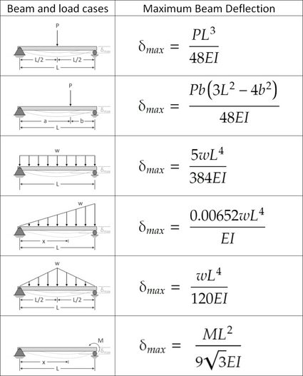
What is the EI formula for deflection?

The EI formula for deflection is a mathematical equation used to calculate the deflection of a beam under load. It is expressed as δ = (W L^3) / (3 E I), where δ is the deflection, W is the load, L is the length of the beam, E is the modulus of elasticity, and I is the moment of inertia.
Understanding the EI Formula Components
The EI formula for deflection is composed of several key components, including the load (W), length (L), modulus of elasticity (E), and moment of inertia (I). These components are crucial in determining the deflection of a beam. The following are the key components:
- Load (W): The force applied to the beam, typically measured in Newtons or pounds.
- Length (L): The distance over which the load is applied, typically measured in meters or feet.
- Modulus of elasticity (E): A measure of a material's ability to resist deformation, typically measured in Pascals or pounds per square inch.
Calculating the Moment of Inertia
The moment of inertia (I) is a critical component of the EI formula, as it represents the beam's resistance to bending. The moment of inertia is calculated using the formula I = (b h^3) / 12, where b is the width of the beam and h is the height. The following are the key steps in calculating the moment of inertia:
- Determine the width (b) and height (h) of the beam.
- Calculate the moment of inertia (I) using the formula I = (b h^3) / 12.
- Use the calculated moment of inertia in the EI formula to determine the deflection.
Applying the EI Formula to Real-World Scenarios
The EI formula for deflection has numerous real-world applications, including the design of bridges, buildings, and machinery. By applying the EI formula, engineers can determine the deflection of a beam under load and ensure that it is within safe and acceptable limits. The following are some examples of real-world applications:
- Bridge design: The EI formula is used to determine the deflection of bridge beams under load, ensuring that they can withstand heavy traffic and weather conditions.
- Building design: The EI formula is used to determine the deflection of building beams and columns, ensuring that they can withstand wind loads and seismic activity.
- Machinery design: The EI formula is used to determine the deflection of machine components, such as shafts and gears, ensuring that they can withstand operating loads and stress.
Factors Affecting the EI Formula
Several factors can affect the accuracy of the EI formula, including the material properties, beam geometry, and load conditions. The following are some of the key factors:
- Material properties: The modulus of elasticity and moment of inertia of the beam material can affect the accuracy of the EI formula.
- Beam geometry: The width, height, and length of the beam can affect the accuracy of the EI formula.
- Load conditions: The type and magnitude of the load can affect the accuracy of the EI formula.
Limitations of the EI Formula
The EI formula has several limitations, including its assumption of a linear elastic response and its failure to account for nonlinear effects, such as plasticity and buckling. The following are some of the key limitations:
- Linear elastic assumption: The EI formula assumes a linear elastic response, which may not be accurate for nonlinear materials or large deformations.
- Nonlinear effects: The EI formula fails to account for nonlinear effects, such as plasticity and buckling, which can significantly affect the deflection of a beam.
- Simplifying assumptions: The EI formula makes several simplifying assumptions, such as neglecting shear deformation and rotational effects, which can affect its accuracy.
Frequently Asked Questions (FAQs)
What is the purpose of the Beam Deflection Calculator for a beam supported at one end and cantilevered at a defined location with a distributed load between supports?
The Beam Deflection Calculator is a tool designed to calculate the deflection and stress of a beam that is supported at one end and cantilevered at a defined location, with a distributed load applied between the supports. This type of beam is commonly used in various engineering applications, such as bridges, buildings, and mechanical systems. The calculator takes into account the length of the beam, the location of the cantilever, the magnitude of the distributed load, and the material properties of the beam to determine the deflection and stress at any point along the beam. By using this calculator, engineers can quickly and accurately determine the structural integrity of the beam and ensure that it can withstand the applied loads.
How does the Beam Deflection Calculator handle the distributed load between supports?
The Beam Deflection Calculator uses a numerical method to handle the distributed load between the supports. The calculator divides the beam into a series of small segments and applies the load to each segment. The deflection and stress are then calculated for each segment, taking into account the load distribution and the boundary conditions of the beam. This approach allows for a highly accurate calculation of the deflection and stress of the beam, even for complex load distributions. The calculator also allows users to specify the type of load distribution, such as a uniformly distributed load or a linearly varying load, to ensure that the calculation is tailored to the specific application.
What are the key parameters that need to be input into the Beam Deflection Calculator?
The key parameters that need to be input into the Beam Deflection Calculator include the length of the beam, the location of the cantilever, the magnitude of the distributed load, and the material properties of the beam. The material properties include the Young's modulus, Poisson's ratio, and the density of the beam material. Additionally, users need to specify the boundary conditions of the beam, such as the support conditions and any restraints on the beam. The calculator also allows users to input optional parameters, such as the damping ratio and the natural frequency of the beam, to further refine the calculation. By inputting these parameters, users can ensure that the calculator provides an accurate and reliable calculation of the deflection and stress of the beam.
What are the limitations and assumptions of the Beam Deflection Calculator?
The Beam Deflection Calculator is based on a linear elastic analysis, which assumes that the beam material behaves in a linear and elastic manner. This means that the calculator is limited to small deflections and low stresses, and is not suitable for large deflections or non-linear behavior. Additionally, the calculator assumes that the beam is prismatic, meaning that the cross-sectional area and moment of inertia are constant along the length of the beam. The calculator also assumes that the load is static, meaning that it does not change over time. Users should be aware of these limitation and assumptions when using the calculator, and should consult the user manual or technical documentation for further information on the validity and accuracy of the calculation. By understanding these limitations, users can ensure that the calculator is used correctly and effectively.
Deja una respuesta
Entradas Relacionadas