
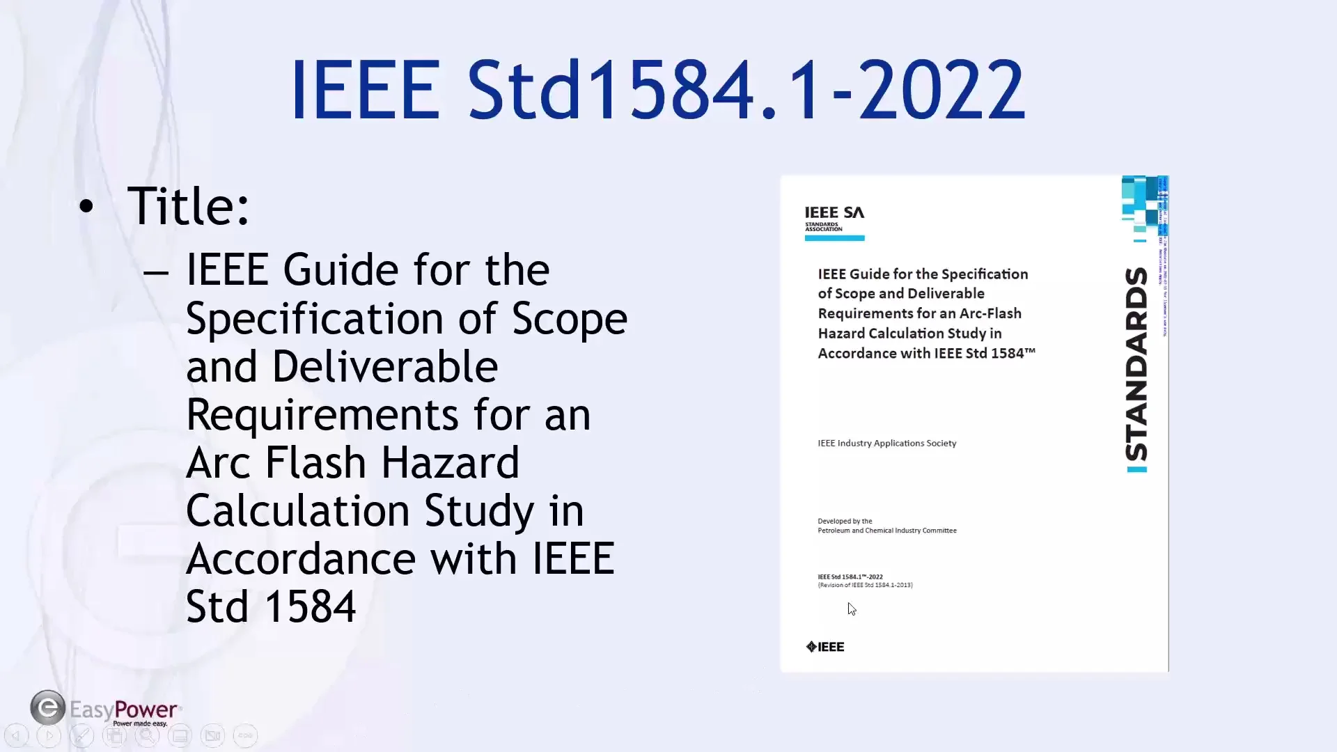
Arc-Flash boundary (AFB) Equations and Calculator per IEEE 1584-2018
The Arc-Flash boundary (AFB) is a critical parameter in electrical safety, representing the maximum distance at which an arc flash can cause severe injury or death. The IEEE 1584-2018 standard provides equations to calculate the AFB, taking into account factors such as system voltage, available short-circuit current, and the duration of the arc. This article will delve into the AFB equations and provide a calculator based on the IEEE 1584-2018 standard, enabling electrical engineers and safety professionals to accurately assess and mitigate arc flash hazards in their systems. Accurate calculations are crucial for ensuring worker safety.
- Arc-Flash Boundary (AFB) Equations and Calculator per IEEE 1584-2018
- How do you calculate arc flash boundary?
- What is the IEEE standard for arc flash study?
- What is the 2 second rule in IEEE 1584 2018?
- What is the AFB in arc flash?
-
Frequently Asked Questions (FAQs)
- What is the Arc-Flash boundary (AFB) and how is it calculated according to IEEE 1584-2018?
- How do the equations in IEEE 1584-2018 account for the variables that affect the Arc-Flash boundary?
- What is the significance of the Arc-Flash boundary (AFB) in ensuring electrical safety, and how is it used in practice?
- Can the Arc-Flash boundary (AFB) equations and calculator in IEEE 1584-2018 be used for all types of electrical equipment and systems?
Arc-Flash Boundary (AFB) Equations and Calculator per IEEE 1584-2018
The Arc-Flash Boundary (AFB) is a critical concept in electrical safety, as it defines the distance from an arc flash source within which a person would receive a second-degree burn from the thermal effects of the arc flash. The IEEE 1584-2018 standard provides equations and a calculator to determine the AFB. These equations take into account various parameters, including the supply voltage, system frequency, fault current, and clearing time. By using these equations and calculator, engineers and safety professionals can determine the AFB and develop appropriate safety protocols to protect workers from the hazards of arc flashes.
Introduction to Arc-Flash Boundary (AFB) Calculations
The calculation of the AFB is based on the incident energy at a given distance from the arc flash source. The incident energy is a measure of the amount of energy that is transferred to a person's skin during an arc flash, causing burns. The AFB is the distance at which the incident energy is equal to the threshold energy for a second-degree burn, which is typically considered to be 5 J/cm². The IEEE 1584-2018 standard provides a detailed methodology for calculating the AFB, including equations for various types of electrical equipment and configurations.
AFB Equations for AC and DC Systems
The AFB equations for AC and DC systems differ due to the different characteristics of AC and DC arc flashes. For AC systems, the AFB equation takes into account the peak current, arcing time, and supply voltage. For DC systems, the AFB equation is based on the AVAILABLE ENERGY and clearing time. The equations are as follows:
| Parameter | AC Systems | DC Systems |
|---|---|---|
| AFB Equation | AFB = (1.732 x V x I x t) / (5 x 10^6) | AFB = (AVAILABLE ENERGY x t) / (5 x 10^6) |
| Units | V (V), I (A), t (s) | AVAILABLE ENERGY (J), t (s) |
The AFB equations are used to calculate the distance from the arc flash source at which a person would receive a second-degree burn.
AFB Calculator per IEEE 1584-2018
The AFB calculator is a tool that is used to determine the AFB based on the input parameters, such as supply voltage, system frequency, fault current, and clearing time. The calculator uses the AFB equations to calculate the distance from the arc flash source at which a person would receive a second-degree burn. The calculator is typically used by engineers and safety professionals to develop safety protocols and to determine the required personal protective equipment (PPE) for workers.
Importance of AFB in Electrical Safety
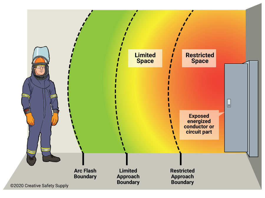
The AFB is a critical concept in electrical safety, as it defines the distance from an arc flash source within which a person would receive a second-degree burn from the thermal effects of the arc flash. The AFB is used to determine the required PPE and safety protocols for workers who are exposed to the hazards of arc flashes. The AFB is also used to develop safety boundaries around electrical equipment to prevent workers from entering the area where they could be exposed to the hazards of arc flashes.
Limitations and Assumptions of AFB Equations
The AFB equations have limitations and assumptions that must be considered when using them to determine the AFB. The equations assume that the arc flash is a three-phase fault, and that the fault current is symmetrical. The equations also assume that the clearing time is less than 2 seconds. Additionally, the equations do not take into account the effect of enclosure on the arc flash, such as the presence of a panel or cabinet. These limitations and assumptions must be considered when using the AFB equations to determine the AFB and to develop safety protocols.
How do you calculate arc flash boundary?
To calculate the arc flash boundary, you need to determine the distance from the electrical equipment at which the incident energy is 1.2 cal/cm², which is the threshold for a second-degree burn. This calculation is typically performed using the IEEE 1584 standard, which provides a method for calculating the arc flash energy and the corresponding boundary distance.
Understanding the IEEE 1584 Standard
The IEEE 1584 standard provides a comprehensive method for calculating the arc flash energy and the corresponding boundary distance. This standard takes into account various factors, including the system voltage, available short-circuit current, and equipment configuration. To calculate the arc flash boundary, you need to follow these steps:
- Obtain the necessary equipment data, including the system voltage and available short-circuit current.
- Use the IEEE 1584 equations to calculate the arc flash energy and the corresponding boundary distance.
- Perform a detailed analysis of the electrical system to ensure that all relevant factors are considered.
Determining the Arc Flash Energy
The arc flash energy is a critical component in calculating the arc flash boundary. This energy is dependent on various factors, including the system voltage, available short-circuit current, and equipment configuration. To determine the arc flash energy, you need to consider the following:
- The system voltage and its impact on the arc flash energy.
- The available short-circuit current and its effect on the arc flash energy.
- The equipment configuration, including the bus spacing and conductor size.
Calculating the Boundary Distance
The boundary distance is the distance from the electrical equipment at which the incident energy is 1.2 cal/cm². To calculate this distance, you need to use the IEEE 1584 equations, which take into account the arc flash energy and other relevant factors. The calculation involves the following steps:
- Determining the arc flash energy and its corresponding incident energy.
- Using the IEEE 1584 equations to calculate the boundary distance.
- Considering the system voltage and available short-circuit current in the calculation.
Factors Affecting the Arc Flash Boundary
Several factors can affect the arc flash boundary, including the system voltage, available short-circuit current, and equipment configuration. To ensure accurate calculations, you need to consider the following:
- The system voltage and its impact on the arc flash energy and boundary distance.
- The available short-circuit current and its effect on the arc flash energy and boundary distance.
- The equipment configuration, including the bus spacing and conductor size, and its impact on the arc flash energy and boundary distance.
Importance of Accurate Calculations
Accurate calculations of the arc flash boundary are critical for ensuring the safety of personnel working on or near electrical equipment. The calculations help determine the safe working distance and the required personal protective equipment (PPE). To ensure accurate calculations, you need to:
- Use the IEEE 1584 standard and its equations to calculate the arc flash energy and boundary distance.
- Consider all relevant factors, including the system voltage, available short-circuit current, and equipment configuration.
- Perform detailed analyses of the electrical system to ensure that all relevant factors are considered.
What is the IEEE standard for arc flash study?
The IEEE standard for arc flash study is IEEE 1584, which provides a method for calculating the arc flash energy released during an electrical arc fault. This standard is widely used in the industry to determine the hazard risk category and the required personal protective equipment (PPE) for workers who may be exposed to arc flash hazards.
Arc Flash Study Requirements
An arc flash study is required for electrical systems with a nominal voltage above 50 volts and a short-circuit capacity of 5 kVA or more. The study involves collecting data on the electrical system, including the overcurrent protective devices, circuit breakers, and fuses, as well as the wiring and equipment. The data is then used to calculate the incident energy and arc flash boundary, which determines the safe working distance. Some of the key steps involved in an arc flash study include:
- Collecting data on the electrical system
- Calculating the incident energy and arc flash boundary
- Determining the safe working distance and hazard risk category
Arc Flash Hazard Analysis
The IEEE standard for arc flash study provides a method for analyzing the arc flash hazard and determining the required PPE. The analysis involves calculating the incident energy, which is the amount of energy released during an arc fault, and the arc flash boundary, which is the distance from the arc source at which the incident energy is 1.2 cal/cm². The incident energy is calculated using the arc flash energy equation, which takes into account the system voltage, short-circuit current, and arc flash duration. Some of the key factors that affect the arc flash hazard include:
- System voltage and short-circuit current
- Arc flash duration and arc flash energy
- Overcurrent protective devices and circuit breakers
Arc Flash Calculations
The IEEE standard for arc flash study provides a method for calculating the incident energy and arc flash boundary. The calculations involve using the arc flash energy equation, which is based on the system voltage, short-circuit current, and arc flash duration. The arc flash energy equation is:
- IES = 4.184 x (CF x (VF^2 / (D^2 x (1 / (TP x (1 + TP))) x (K1 + (K2 x D))))))
- Where IES is the incident energy, CF is the correction factor, VF is the system voltage, D is the distance from the arc source, TP is the trip time of the overcurrent protective device, and K1 and K2 are constants
- The arc flash boundary is calculated using the incident energy and the safe working distance
Arc Flash Mitigation
The IEEE standard for arc flash study provides a method for mitigating the arc flash hazard. The mitigation involves using arc flash reduction methods, such as arc flash relays and arc fault circuit interrupters. These devices can detect an arc fault and trip the overcurrent protective device to reduce the arc flash energy. Some of the key arc flash reduction methods include:
- Arc flash relays and arc fault circuit interrupters
- Arc flash limiting devices, such as fuses and circuit breakers
- Arc flash protection devices, such as personal protective equipment and arc flash suits
Arc Flash Safety
The IEEE standard for arc flash study emphasizes the importance of arc flash safety. The standard provides guidelines for safe working practices, including the use of personal protective equipment, such as arc flash suits and eye protection. The standard also requires that workers be trained on the hazards of arc flash and the procedures for handling arc flash emergencies. Some of the key arc flash safety guidelines include:
- Wearing personal protective equipment, such as arc flash suits and eye protection
- Following safe working practices, such as lockout/tagout and electrical isolation
- Receiving training on arc flash hazards and emergency procedures
What is the 2 second rule in IEEE 1584 2018?
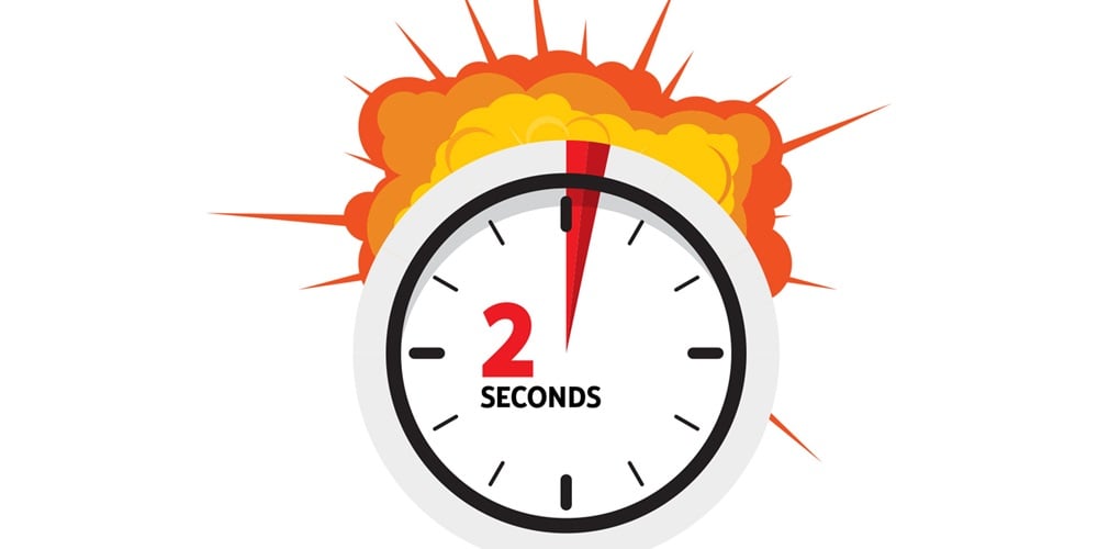
The 2-second rule in IEEE 1584-2018 is a guideline that specifies the maximum duration of an arc flash event. This rule is crucial in determining the incident energy that a worker may be exposed to during an arc flash event. The 2-second rule is based on the assumption that the arc flash event will be cleared by the circuit breaker or other protective devices within 2 seconds.
Understanding the 2-Second Rule
The 2-second rule is a critical component of the IEEE 1584-2018 standard, which provides a method for calculating the incident energy of an arc flash event. This rule is used to determine the arc flash boundary, which is the distance from the arc flash source that a worker can safely be without being exposed to a significant amount of incident energy. The 2-second rule is based on the following assumptions:
- The arc flash event will be cleared by the circuit breaker or other protective devices within 2 seconds.
- The incident energy will be limited to a specific value that is determined by the arc flash model.
- The worker will be protected from the arc flash event by wearing personal protective equipment (PPE) that is rated for the expected incident energy.
Calculating Incident Energy
To calculate the incident energy of an arc flash event, the IEEE 1584-2018 standard provides a method that takes into account the system voltage, available short-circuit current, and the distance from the arc flash source. The 2-second rule is used to determine the incident energy that a worker may be exposed to during an arc flash event. The calculation is based on the following parameters:
- System voltage: The voltage of the electrical system that is being analyzed.
- Available short-circuit current: The maximum amount of current that can flow through the system during an arc flash event.
- Distance: The distance from the arc flash source to the worker.
Application of the 2-Second Rule
The 2-second rule is applied in various industries and applications, including electrical power systems, industrial control systems, and commercial buildings. The rule is used to determine the arc flash boundary and the incident energy that a worker may be exposed to during an arc flash event. The application of the 2-second rule involves the following steps:
- Determine the system voltage and available short-circuit current.
- Calculate the incident energy using the IEEE 1584-2018 standard.
- Determine the arc flash boundary based on the calculated incident energy.
Importance of the 2-Second Rule
The 2-second rule is essential in ensuring the safety of workers who are exposed to arc flash events. The rule provides a guideline for determining the incident energy that a worker may be exposed to during an arc flash event, and it helps to prevent injuries and fatalities. The importance of the 2-second rule can be seen in the following aspects:
- Prevents injuries and fatalities: The 2-second rule helps to prevent injuries and fatalities by providing a guideline for determining the incident energy.
- Ensures compliance with regulations: The 2-second rule helps to ensure compliance with regulations and standards related to arc flash safety.
- Provides a safe working environment: The 2-second rule helps to provide a safe working environment for workers who are exposed to arc flash events.
Limitations of the 2-Second Rule
The 2-second rule has some limitations that need to be considered when applying it in practice. The rule is based on assumptions and simplifications that may not always reflect the real-world scenario. The limitations of the 2-second rule include the following aspects:
- Assumes a 2-second clearance time: The 2-second rule assumes that the arc flash event will be cleared by the circuit breaker or other protective devices within 2 seconds.
- Does not account for all variables: The 2-second rule does not account for all variables that can affect the incident energy, such as cable and conductor characteristics.
- May not be applicable in all situations: The 2-second rule may not be applicable in all situations, such as in high-voltage systems or in systems with complex configurations.
What is the AFB in arc flash?
The AFB in arc flash refers to the Arc Flash Boundary, which is a critical concept in electrical safety. It represents the distance from an arc flash source within which a person would likely receive second-degree burns or worse if an arc flash were to occur. The AFB is typically calculated using the NFPA 70E standard, which provides guidelines for electrical safety in the workplace. Understanding the AFB is essential for electrical workers to take necessary precautions and wear personal protective equipment (PPE) to prevent injuries.
Arc Flash Boundary Calculations
The AFB calculations involve several factors, including the distance from the arc flash source, the incident energy released during the arc flash, and the working distance of the electrical worker. To calculate the AFB, electrical engineers use complex formulas that take into account the available short-circuit current, system voltage, and arc duration. The calculations are typically performed using specialized software or online tools. Some key factors to consider when calculating the AFB include:
- Voltage: The system voltage has a significant impact on the AFB calculation, as higher voltages result in higher incident energy levels.
- Short-circuit current: The available short-circuit current also affects the AFB, as higher current levels result in higher incident energy levels.
- Arc duration: The duration of the arc flash event also impacts the AFB calculation, as longer arc durations result in higher incident energy levels.
Importance of Arc Flash Boundary
The AFB is a critical concept in electrical safety, as it helps electrical workers understand the risks associated with arc flash events. By calculating the AFB, workers can determine the safe working distance from the arc flash source and take necessary precautions to prevent injuries. The AFB also helps employers develop safety protocols and provide training to workers on how to work safely with electrical systems. Some key benefits of understanding the AFB include:
- Reduced risk of injury: By understanding the AFB, workers can reduce their risk of injury from arc flash events.
- Improved safety protocols: Employers can develop more effective safety protocols by understanding the AFB and the risks associated with arc flash events.
- Compliance with regulations: Understanding the AFB helps employers comply with regulatory requirements, such as those outlined in NFPA 70E.
Arc Flash Boundary Marking
The AFB should be clearly marked on electrical equipment and in the surrounding area to alert workers to the potential hazards. The marking should include the distance from the arc flash source and the incident energy level at that distance. The marking should also include any necessary safety warnings or cautions. Some key considerations when marking the AFB include:
- Visibility: The marking should be clearly visible to workers in the area.
- Durability: The marking should be durable and able to withstand the environmental conditions in which it is located.
- Accuracy: The marking should accurately reflect the calculated AFB and incident energy level.
Personal Protective Equipment (PPE)
Workers who are required to work within the AFB must wear personal protective equipment (PPE) to protect themselves from the risks associated with arc flash events. The PPE should be selected based on the incident energy level at the working distance and should include items such as arc-rated clothing, hard hat, and safety glasses. Some key considerations when selecting PPE include:
- Arc rating: The PPE should have an arc rating that is equal to or greater than the incident energy level at the working distance.
- Comfort: The PPE should be comfortable to wear and not restrict the worker's movement.
- Maintenance: The PPE should be regularly inspected and maintained to ensure it remains effective.
Training and Awareness
Workers who are required to work with electrical systems must receive training on the risks associated with arc flash events and the importance of understanding the AFB. The training should include information on safety protocols, PPE selection, and emergency procedures. Some key considerations when providing training include:
- Frequency: The training should be provided on a regular basis, such as annually, to ensure workers remain aware of the risks and procedures.
- Content: The training should include information on the AFB, incident energy levels, and PPE selection.
- Practical application: The training should include practical applications and scenarios to help workers understand how to apply the knowledge in real-world situations.
Frequently Asked Questions (FAQs)
What is the Arc-Flash boundary (AFB) and how is it calculated according to IEEE 1584-2018?
The Arc-Flash boundary (AFB) is the distance from the arc flash source within which a person would receive a second-degree burn (i.e., a burn that would cause a person to require medical treatment) from the thermal radiation emitted by an arc flash. The IEEE 1584-2018 standard provides a method for calculating the AFB using a set of equations that take into account various factors, including the short-circuit current, system voltage, arc duration, and distance from the arc flash source. These equations are based on empirical data and are designed to provide a conservative estimate of the AFB. The calculation of the AFB is an important step in determining the safety boundaries for personnel working on or near electrical equipment.
How do the equations in IEEE 1584-2018 account for the variables that affect the Arc-Flash boundary?
The equations in IEEE 1584-2018 account for several variables that affect the Arc-Flash boundary (AFB), including the short-circuit current, system voltage, arc duration, and distance from the arc flash source. The equations use a combination of calculations and look-up tables to determine the incident energy at a given distance from the arc flash source. The incident energy is then compared to a threshold value to determine whether a second-degree burn would occur at that distance. The equations also take into account the type of equipment and the configuration of the electrical system. By accounting for these variables, the equations provide a more accurate estimate of the AFB and help to ensure that personnel are protected from the hazards of arc flashes.
What is the significance of the Arc-Flash boundary (AFB) in ensuring electrical safety, and how is it used in practice?
The Arc-Flash boundary (AFB) is a critical factor in ensuring electrical safety because it provides a clear boundary beyond which personnel are at risk of receiving a second-degree burn from an arc flash. The AFB is used in practice to determine the safety boundaries for personnel working on or near electrical equipment. For example, personnel may be required to wear personal protective equipment (PPE), such as arc-rated clothing and face shields, when working within the AFB. The AFB is also used to determine the safe working distance for personnel and to identify hazardous areas where warning signs and barriers may be required. By understanding the AFB and taking steps to protect personnel from the hazards of arc flashes, employers can help to prevent injuries and fatalities and ensure a safe working environment.
Can the Arc-Flash boundary (AFB) equations and calculator in IEEE 1584-2018 be used for all types of electrical equipment and systems?
The Arc-Flash boundary (AFB) equations and calculator in IEEE 1584-2018 are designed to be used for a wide range of electrical equipment and systems, including low-voltage and medium-voltage systems. However, there are some limitations to their use. For example, the equations are not suitable for use with high-voltage systems or with equipment that has a high degree of complexity. Additionally, the equations assume that the arc flash source is a three-phase system, and may not be applicable to single-phase or dc systems. Furthermore, the equations do not account for non-standard or custom-built equipment, and may require additional analysis or modifications to be used in these cases. Therefore, it is essential to carefully review the scope and limitations of the IEEE 1584-2018 standard and to consult with a qualified engineer or electrical safety expert if there are any doubts about the applicability of the AFB equations and! calculator to a specific electrical system or equipment.
Deja una respuesta
Entradas Relacionadas