
True Position GD&T Tolerance Calculator

The True Position GD&T Tolerance Calculator is a vital tool in the field of engineering and manufacturing. Geometric Dimensioning and Tolerancing (GD&T) is a system used to define the tolerance of a part's dimensions and geometry. The True Position calculator allows users to calculate the tolerance of a feature's position, ensuring that it meets the required specifications. This calculator is essential for designers, engineers, and manufacturers to verify that their parts meet the desired standards, reducing errors and improving overall product quality and reliability. It provides a straightforward and accurate method for calculating true position tolerances.
- Understanding the True Position GD&T Tolerance Calculator
- How do you calculate bonus tolerance in true position?
- How to determine tolerance in GD&T?
- Does true position need a datum?
-
Frequently Asked Questions (FAQs)
- What is True Position GD&T Tolerance Calculator and how does it work?
- How do I use the True Position GD&T Tolerance Calculator to calculate the true position of a feature?
- What are the benefits of using the True Position GD&T Tolerance Calculator in manufacturing and quality control?
- How does the True Position GD&T Tolerance Calculator handle complex GD&T specifications and features?
Understanding the True Position GD&T Tolerance Calculator
The True Position GD&T Tolerance Calculator is a tool used to calculate the tolerance of a part's true position, which is a critical aspect of Geometric Dimensioning and Tolerancing (GD&T). This calculator helps designers and engineers determine the allowable variation in the position of a feature, ensuring that it meets the required specifications and standards.
What is True Position in GD&T?
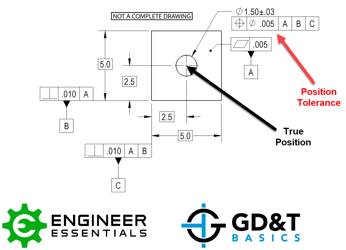
True Position is a GD&T concept that refers to the theoretical position of a feature, considering its ideal location, size, and orientation. It is a reference point for evaluating the actual position of the feature, taking into account tolerances and deviations. The True Position calculator helps to determine the maximum allowable deviation from the true position, ensuring that the part meets the required standards and specifications.
How to Use the True Position GD&T Tolerance Calculator?
To use the True Position GD&T Tolerance Calculator, users need to input the following parameters:
- Feature size
- Tolerance zone
- Material condition (e.g., Maximum Material Condition (MMC) or Least Material Condition (LMC))
- Geometric tolerance (e.g., position, orientation, or profile)
The calculator then outputs the tolerance value, which represents the allowable variation in the feature's true position.
Benefits of Using the True Position GD&T Tolerance Calculator
The True Position GD&T Tolerance Calculator offers several benefits, including:
- Improved accuracy: By calculating the true position tolerance, designers and engineers can ensure that parts meet the required specifications and standards.
- Reduced errors: The calculator helps to minimize errors and deviations in the manufacturing process, resulting in higher quality parts.
- Increased efficiency: By streamlining the tolerance calculation process, the calculator saves time and resources, allowing designers and engineers to focus on other critical aspects of the design.
Common Applications of the True Position GD&T Tolerance Calculator
The True Position GD&T Tolerance Calculator is commonly used in various industries, including:
- Aerospace
- Automotive
- Medical devices
- Consumer products
In these industries, the calculator is used to ensure that parts meet the required standards and specifications, and to minimize errors and deviations in the manufacturing process.
Comparison of True Position Tolerance Calculator with Other Tools
The following table compares the True Position Tolerance Calculator with other tools and methods:
| Tool/Method | Accuracy | Ease of use | Cost |
|---|---|---|---|
| True Position Tolerance Calculator | High | Easy | Low |
| Manual calculation | Low | Difficult | High |
| Other software tools | Medium | Medium | Medium |
The True Position Tolerance Calculator offers high accuracy, ease of use, and low cost, making it a popular choice among designers and engineers.
How do you calculate bonus tolerance in true position?
The calculation of bonus tolerance in true position involves understanding the concept of geometric dimensioning and tolerancing (GD&T). To calculate the bonus tolerance, you need to determine the actual size of the feature and compare it to the specified size. The bonus tolerance is the amount of tolerance that is added to the specified tolerance when the actual size of the feature is closer to the nominal size.
Understanding True Position
The true position of a feature is its theoretical location in space, taking into account the nominal dimensions and tolerances specified in the design. To calculate the true position, you need to consider the datum features and the tolerance zones specified in the design. The true position is used as a reference point to calculate the bonus tolerance.
- The datum features are the reference points used to establish the coordinate system for the part.
- The tolerance zones are the regions within which the feature must be located to meet the specifications.
- The true position is calculated by combining the datum features and tolerance zones to determine! the theoretical location of the feature.
Calculating Bonus Tolerance
The bonus tolerance is calculated by subtracting the actual deviation from the specified tolerance. The actual deviation is the difference between the actual size of the feature and the specified size. The specified tolerance is the allowable variation in size specified in the design.
- The actual deviation is calculated by measuring the actual size of the feature and comparing it to the specified size.
- The specified tolerance is specified in the design and is the maximum allowable variation in size.
- The bonus tolerance is calculated by subtracting the actual deviation from the specified tolerance.
Applying Geometric Dimensioning and Tolerancing
Geometric dimensioning and tolerancing (GD&T) is a system of symbols and rules used to specify the tolerances and relationships between features on a part. GD&T is used to ensure that the part meets the requirements specified in the design. The bonus tolerance is an important concept in GD&T, as it allows for greater flexibility in the manufacturing process.
- GD&T is used to specify the tolerances and relationships between features on a part.
- The bonus tolerance is an important concept in GD&T, as it allows for greater flexibility in the manufacturing process.
- GD&T is used to ensure that the part meets the requirements specified in the design.
Considering Datum Features
The datum features are the reference points used to establish the coordinate system for the part. The datum features are used to locate the feature in space and to calculate the true position. The datum features must be specified in the design and must be measurable.
- The datum features are the reference points used to establish the coordinate system for the part.
- The datum features are used to locate the feature in space and to calculate the true position.
- The datum features must be specified in the design and must be measurable.
Using Tolerance Zones
The tolerance zones are the regions within which the feature must be located to meet the specifications. The tolerance zones are used to calculate the true position and to determine the bonus tolerance. The tolerance zones must be specified in the design and must be measurable.
- The tolerance zones are the regions within which the feature must be located to meet the specifications.
- The tolerance zones are used to calculate the true position and to determine the bonus tolerance.
- The tolerance zones must be specified in the design and must be measurable.
How to determine tolerance in GD&T?
To determine tolerance in Geometric Dimensioning and Tolerancing (GD&T), it's essential to understand the fundamentals of GD&T and how tolerances are applied to geometric features. Tolerance in GD&T refers to the allowable variation in the size or location of a feature. The tolerance is specified using a tolerance zone, which defines the limits within which the feature must be produced. The tolerance zone is typically defined by a nominal size and a tolerance value, which specifies the amount of variation allowed.
Determining Tolerance Zones
Determining tolerance zones in GD&T involves identifying the type of feature being toleranced, such as a hole or a shaft, and the type of tolerance being applied, such as size tolerance or location tolerance. The tolerance zone is then defined by the nominal size and the tolerance value, which specifies the amount of variation allowed. For example, a hole with a nominal size of 10mm and a tolerance value of ±0.1mm would have a tolerance zone of 9.9mm to 10.1mm.
- The nominal size is the ideal size of the feature.
- The tolerance value specifies the amount of variation allowed.
- The tolerance zone is the range of sizes within which the feature must be produced.
Types of Tolerances
There are several types of tolerances used in GD&T, including size tolerance, location tolerance, and orientation tolerance. Size tolerance refers to the allowable variation in the size of a feature, while location tolerance refers to the allowable variation in the location of a feature. Orientation tolerance refers to the allowable variation in the orientation of a feature. Each type of tolerance has its own set of rules and specifications for how it is applied.
- Size tolerance is used to control the size of a feature.
- Location tolerance is used to control the location of a feature.
- Orientation tolerance is used to control the orientation of a feature.
Tolerance Specifications
Tolerance specifications in GD&T are typically dimensional and geometric, and are used to define the limits of the tolerance zone. The tolerance specification includes the nominal size, the tolerance value, and the type of tolerance being applied. The tolerance specification is usually indicated on the drawing or specification using a tolerance symbol or notation. For example, a tolerance specification of 10mm ±0.1mm would indicate that the nominal size is 10mm and the tolerance value is ±0.1mm.
- The tolerance specification includes the nominal size and the tolerance value.
- The type of tolerance being applied is also specified.
- The tolerance specification is usually indicated on the drawing or specification.
Calculating Tolerances
Calculating tolerances in GD&T involves determining the tolerance zone and applying the tolerance specification. The tolerance zone is calculated by adding and subtracting the tolerance value from the nominal size. For example, a hole with a nominal size of 10mm and a tolerance value of ±0.1mm would have a tolerance zone of 9.9mm to 10.1mm. The tolerance specification is then applied to ensure that the feature is produced within the tolerance zone.
- The tolerance zone is calculated by adding and subtracting the tolerance value.
- The tolerance specification is applied to ensure that the feature is produced within the tolerance zone.
- The tolerance zone is used to control the variation in the feature.
Interpreting Tolerance Specifications
Interpreting tolerance specifications in GD&T involves understanding the notation and symbols used to indicate the tolerance specification. The tolerance specification is usually indicated on the drawing or specification using a tolerance symbol or notation. For example, a tolerance specification of 10mm ±0.1mm would indicate that the nominal size is 10mm and the tolerance value is ±0.1mm. The tolerance specification must be clearly understood to ensure that the feature is produced within the tolerance zone.
- The tolerance specification is usually indicated on the drawing or specification.
- The tolerance symbol or notation is used to indicate the tolerance specification.
- The tolerance specification must be clearly understood to ensure that the feature is produced within the tolerance zone.
Does true position need a datum?
The concept of true position in engineering and geometric dimensioning and tolerancing (GD&T) refers to the exact location of a feature or a part in space, considering its ideal geometry and position. A datum is a reference point, line, or surface from which measurements are taken. In the context of true position, a datum is essential to define the coordinate system and establish a reference frame for measuring the position and orientation of features.
Understanding True Position and Datum
The true position of a feature is its theoretical location in space, and it is used as a reference point for tolerance analysis. A datum is necessary to determine the true position of a feature, as it provides a fixed reference point for measurement. The datum can be a physical feature on the part, such as a surface or an edge, or it can be a theoretical construct, such as a coordinate system. Some key points to consider are:
- The datum must be well-defined and accessible for measurement.
- The datum should be stable and unambiguous to ensure reliable measurements.
- The true position of a feature is dependent on the datum used as a reference.
Datum Influence on True Position
The choice of datum can significantly influence the true position of a feature. A well-chosen datum can simplify the measurement process and reduce uncertainty, while a poorly chosen datum can lead to errors and inconsistencies. It is essential to consider the relationship between the datum and the feature being measured, as well as the measurement method used. Some key considerations are:
- The datum should be relevant to the feature being measured.
- The measurement method should be compatible with the datum chosen.
- The uncertainty associated with the datum should be evaluated and considered.
Types of Datums Used in True Position
There are several types of datums that can be used to determine the true position of a feature, including point datums, line datums, and surface datums. Each type of datum has its own advantages and disadvantages, and the choice of datum will depend on the specific application and measurement requirements. Some key points to consider are:
- Point datums are simple and easy to establish, but may not provide sufficient reference information.
- Line datums provide a one-dimensional reference and can be used to establish a coordinate system.
- Surface datums provide a two-dimensional reference and can be used to establish a plane of reference.
Establishing a Datum for True Position
Establishing a datum for true position measurement involves defining the reference point, line, or surface, and ensuring that it is accessible and measurable. The datum should be clearly defined and documented, and the measurement method should be established and validated. Some key steps to consider are:
- Define the datum and its relationship to the feature being measured.
- Establish the measurement method and validate its accuracy and reliability.
- Document the datum and measurement method for future reference and traceability.
Best Practices for Using Datums in True Position
To ensure accurate and reliable true position measurements, it is essential to follow best practices for using datums. This includes selecting a suitable datum, establishing a clear and unambiguous reference frame, and validating the measurement method. Some key best practices to consider are:
- Choose a datum that is relevant to the feature being measured and the measurement method used.
- Establish a clear and unambiguous reference frame to ensure consistent measurements.
- Validate the measurement method and ensure that it is accurate and reliable.
Frequently Asked Questions (FAQs)
What is True Position GD&T Tolerance Calculator and how does it work?
The True Position GD&T Tolerance Calculator is a tool used to calculate the true position of a feature on a part, taking into account the geometric dimensioning and tolerancing (GD&T) specifications. It works by analyzing the datums, tolerances, and feature control frames specified in the GD&T drawing or specification. The calculator then uses this information to determine the allowed variation in the position of the feature, ensuring that it is within the specified tolerance zone. This is crucial in manufacturing and quality control, as it helps to ensure that parts are produced to the required specifications and standards. By using the True Position GD&T Tolerance Calculator, engineers and quality control specialists can quickly and accurately determine the true position of a feature, reducing the risk of errors and rework.
How do I use the True Position GD&T Tolerance Calculator to calculate the true position of a feature?
To use the True Position GD&T Tolerance Calculator, you need to input the relevant GD&T information, including the datums, tolerances, and feature control frames. The calculator will then prompt you to enter the actual measurements of the feature, which can be obtained using measurement tools such as calipers or coordinate measuring machines (CMMs). Once the input data is complete, the calculator will perform the necessary calculations to determine the true position of the feature. The result will be displayed in a user-friendly format, showing the allowed variation in the position of the feature and indicating whether it is within the specified tolerance zone. The True Position GD&T Tolerance Calculator can be used for a variety of applications, including manufacturing, quality control, and design verification. By following the instructions and inputting the required data, users can quickly and accurately calculate the true position of a feature using this powerful tool.
What are the benefits of using the True Position GD&T Tolerance Calculator in manufacturing and quality control?
The True Position GD&T Tolerance Calculator offers several benefits in manufacturing and quality control, including improved accuracy, reduced errors, and increased efficiency. By using this tool, engineers and quality control specialists can quickly and accurately determine the true position of a feature, reducing the risk of rework and scrap. The calculator also helps to ensure that parts are produced to the required specifications and standards, which is critical in industries such as aerospace, automotive, and medical devices. Additionally, the True Position GD&T Tolerance Calculator can be used to verify designs, ensuring that they are manufacturable and meet the required specifications. Overall, the use of this calculator can help to streamline manufacturing processes, reduce costs, and improve product quality. By leveraging the power of the True Position GD&T Tolerance Calculator, companies can gain a competitive advantage in the marketplace and achieve success in their respective industries.
How does the True Position GD&T Tolerance Calculator handle complex GD&T specifications and features?
The True Position GD&T Tolerance Calculator is designed to handle complex GD&T specifications and features with ease. It can accommodate a wide range of datums, tolerances, and feature control frames, including composite tolerances, orientation tolerances, and position tolerances. The calculator can also handle complex features such as curves, surfaces, and profiles, which are commonly found in aerospace, automotive, and medical devices. To handle these complex specifications and features, the calculator uses advanced algorithms and mathematical models that take into account the interactions between different datums, tolerances, and features. The result is a highly accurate and reliable calculation of the true position of the feature, even in the presence of complex GD&T specifications and features. By using the True Position GD&T Tolerance Calculator, engineers and quality control specialists can confidently analyze and verify complex GD&T specifications and features, ensuring that parts are produced to the required specifications and standards.
Deja una respuesta
Entradas Relacionadas