
Solid Elliptical Section Torsional Deformation Torsional Deformation Stress Equation and Calculator
The solid elliptical section torsional deformation is a crucial concept in engineering mechanics, particularly in the design and analysis of shafts and beams. When a torsional load is applied to a solid elliptical section, it undergoes deformation, resulting in shear stresses. The torsional deformation stress equation is used to calculate these stresses, which is essential for determining the structural integrity of the section. This article provides an in-depth exploration of the torsional deformation stress equation and offers a calculator to simplify the calculation process for engineers and designers. Accurate calculations are vital for safe design.
- Solid Elliptical Section Torsional Deformation: Understanding the Torsional Deformation Stress Equation and Calculator
- What is the formula for torsional deformation and stress?
- How do you calculate stress from torque?
- How to calculate torsional resistance?
-
Frequently Asked Questions (FAQs)
- What is the Solid Elliptical Section Torsional Deformation and how is it calculated?
- What are the key factors that affect the Torsional Deformation Stress Equation and Calculator?
- How is the Torsional Deformation Stress Equation used in engineering applications?
- What are the limitations and assumptions of the Solid Elliptical Section Torsional Deformation Torsional Deformation Stress Equation and Calculator?
Solid Elliptical Section Torsional Deformation: Understanding the Torsional Deformation Stress Equation and Calculator
The solid elliptical section torsional deformation is a critical concept in mechanics of materials, particularly in the context of torsion and stress analysis. When a solid elliptical section is subjected to a torsional load, it undergoes a deformation that can be complex to analyze. The torsional deformation stress equation is used to calculate the stress and strain in the section due to the applied torque. The equation takes into account the polar moment of inertia, section modulus, and torsional rigidity of the section.
Introduction to Torsional Deformation
Torsional deformation occurs when a twisting force is applied to a section, causing it to rotate about its longitudinal axis. The solid elliptical section is particularly susceptible to torsional deformation due to its non-circular shape. The torsional deformation stress equation is used to calculate the maximum shear stress and angle of twist in the section.
Torsional Deformation Stress Equation
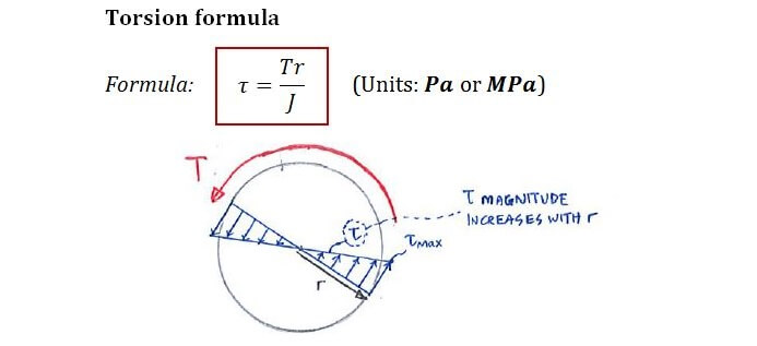
The torsional deformation stress equation is given by:
τ = (T r) / (J p)
where τ is the maximum shear stress, T is the applied torque, r is the distance from the axis of rotation, J is the polar moment of inertia, and p is the perimeter of the section. This equation is used to calculate the stress and strain in the section due to the applied torque.
Polar Moment of Inertia and Section Modulus
The polar moment of inertia (J) is a measure of the resistance of the section to torsional deformation. It is calculated using the formula:
J = (π (a^4 - b^4)) / 16
where a and b are the major and minor axes of the elliptical section. The section modulus (W) is also used to calculate the stress and strain in the section.
| Section Property | Formula |
|---|---|
| Polar Moment of Inertia (J) | (π (a^4 - b^4)) / 16 |
| Section Modulus (W) | (J / (a (a^2 - b^2))) |
Torsional Rigidity and Stiffness
The torsional rigidity (GJ) is a measure of the resistance of the section to torsional deformation. It is calculated using the formula:
GJ = (G J)
where G is the modulus of rigidity. The torsional stiffness (K) is also used to calculate the angle of twist in the section.
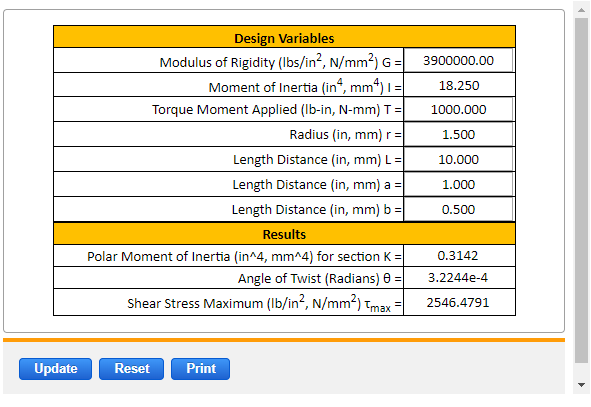
Calculator for Torsional Deformation Stress Equation
A calculator can be used to solve the torsional deformation stress equation. The calculator takes into account the input parameters such as the applied torque, polar moment of inertia, section modulus, and distance from the axis of rotation. The calculator then outputs the maximum shear stress, angle of twist, and torsional rigidity of the section. The calculator is a useful tool for engineers and designers who need to analyze the torsional deformation of solid elliptical sections.
Applications of Torsional Deformation Stress Equation
The torsional deformation stress equation has many applications in engineering and design. It is used to analyze the torsional deformation of shafts, beams, and frames. The equation is also used to design machinery and mechanisms that are subject to torsional loads. The calculator for the torsional deformation stress equation is a useful tool for engineers and designers who need to analyze and design solid elliptical sections that are subject to torsional deformation.
What is the formula for torsional deformation and stress?
The formula for torsional deformation and stress is given by the following equations:
θ = (TL)/((GJ)) and τ = (Tr)/J,
where θ is the angle of twist, T is the applied torque, L is the length of the shaft, G is the shear modulus, J is the polar moment of inertia, τ is the shear stress, and r is the radius of the shaft.
Torsional Deformation Formula
The formula for torsional deformation is θ = (TL)/((GJ)), where θ is the angle of twist, T is the applied torque, L is the length of the shaft, G is the shear modulus, and J is the polar moment of inertia. This formula is used to calculate the angle of twist of a shaft under a given torque. The key factors that affect the torsional deformation are:
- The torque applied to the shaft, which causes the shaft to twist
- The length of the shaft, which affects the amount of twist
- The shear modulus of the material, which determines the shaft's resistance to twisting
Torsional Stress Formula
The formula for torsional stress is τ = (Tr)/J, where τ is the shear stress, T is the applied torque, r is the radius of the shaft, and J is the polar moment of inertia. This formula is used to calculate the shear stress in a shaft under a given torque. The key factors that affect the torsional stress are:
- The torque applied to the shaft, which causes the shaft to twist and creates shear stress
- The radius of the shaft, which affects the amount of shear stress
- The polar moment of inertia, which determines the shaft's resistance to twisting and affects the shear stress
Importance of Polar Moment of Inertia
The polar moment of inertia (J) is a crucial factor in both the torsional deformation and stress formulas. It is a measure of the shaft's resistance to twisting and is dependent on the shaft's cross-sectional shape and size. A higher polar moment of inertia means that the shaft is more resistant to twisting and will experience less torsional deformation and stress. The key factors that affect the polar moment of inertia are:
- The cross-sectional shape of the shaft, which can be circular, rectangular, or other shapes
- The size of the shaft, which affects the polar moment of inertia
- The material of the shaft, which can affect the polar moment of inertia
Applications of Torsional Deformation and Stress
The formulas for torsional deformation and stress have numerous applications in engineering and design. They are used to calculate the torsional deformation and stress in shafts, axles, and other rotating machinery. The key applications are:
- Power transmission systems, where torsional deformation and stress can affect the efficiency and reliability of the system
- Aerospace engineering, where torsional deformation and stress can affect the performance and safety of aircraft and spacecraft
- Automotive engineering, where torsional deformation and stress can affect the performance and safety of vehicles
Limitations and Assumptions
The formulas for torsional deformation and stress are based on several assumptions and limitations. They assume that the shaft is circular and uniform, and that the torque is applied statically. They also assume that the material of the shaft is isotropic and homogeneous. The key limitations and assumptions are:
- The circular and uniform shape of the shaft, which can affect the accuracy of the calculations
- The static application of the torque, which can affect the accuracy of the calculations
- The isotropic and homogeneous material of the shaft, which can affect the accuracy of the calculations
How do you calculate stress from torque?
The calculation of stress from torque involves understanding the relationship between the applied torque, the moment of inertia, and the polar moment of inertia of a shaft or a beam. The stress caused by torque is known as torsional stress, which causes a material to deform by twisting. To calculate stress from torque, we use the formula: τ = T r / J, where τ is the torsional stress, T is the applied torque, r is the radius of the shaft, and J is the polar moment of inertia.
Understanding Torsional Stress
Torsional stress occurs when a torque is applied to a shaft or a beam, causing it to twist. This type of stress is important in designing shafts and beams that are subject to torque. The calculation of torsional stress involves understanding the polar moment of inertia, which is a measure of the resistance of a shaft or a beam to torsional stress. The formula for torsional stress is:
- τ = T r / J is the formula for torsional stress, where τ is the torsional stress, T is the applied torque, r is the radius of the shaft, and J is the polar moment of inertia.
- The polar moment of inertia (J) is a measure of the resistance of a shaft or a beam to torsional stress.
- The radius (r) of the shaft is also important in calculating torsional stress, as it affects the distribution of stress within the material.
Calculating Polar Moment of Inertia
The polar moment of inertia (J) is a critical parameter in calculating torsional stress. It is a measure of the resistance of a shaft or a beam to torsional stress. The polar moment of inertia can be calculated using the formula: J = π d^4 / 32 for a circular shaft, where d is the diameter of the shaft. The calculation of polar moment of inertia involves:
- Calculating the diameter (d) of the shaft, which is used to calculate the polar moment of inertia.
- Using the formula J = π d^4 / 32 to calculate the polar moment of inertia.
- Understanding the units of the polar moment of inertia, which is typically measured in mm^4 or in^4.
Applying Torque to Calculate Stress
Torque is a measure of the rotational force applied to a shaft or a beam. To calculate stress from torque, we need to know the applied torque and the polar moment of inertia of the shaft or beam. The formula τ = T r / J can be used to calculate the torsional stress. The application of torque to calculate stress involves:
- Measuring the applied torque (T), which can be done using a torque meter or by calculating it from the rotational force and the radius of the shaft.
- Calculating the radius (r) of the shaft, which is used to calculate the torsional stress.
- Using the formula τ = T r / J to calculate the torsional stress.
Material Properties and Torsional Stress
The material properties of a shaft or a beam, such as its elastic modulus and Poisson's ratio, can affect the calculation of torsional stress. The elastic modulus (E) is a measure of the stiffness of a material, while Poisson's ratio (ν) is a measure of the lateral strain response to axial loading. The material properties can be used to calculate the polar moment of inertia and the torsional stress. The relationship between material properties and torsional stress involves:
- Understanding the elastic modulus (E) of the material, which affects the stiffness of the shaft or beam.
- Calculating Poisson's ratio (ν), which affects the lateral strain response to axial loading.
- Using the material properties to calculate the polar moment of inertia and the torsional stress.
Design Considerations for Torsional Stress
The design of a shaft or a beam subject to torque requires careful consideration of torsional stress. The design should ensure that the torsional stress is within the safe limits of the material to avoid failure. The design considerations for torsional stress involve:
- Calculating the maximum allowable torque (T) that can be applied to the shaft or beam without causing failure.
- Selecting a material with a high elastic modulus and high strength to minimize torsional stress.
- Optimizing the design of the shaft or beam to minimize torsional stress and ensure safe operation.
How to calculate torsional resistance?

To calculate torsional resistance, it's essential to understand the concept of torsion and its effects on a material. Torsion occurs when a force is applied to an object, causing it to twist or rotate about its axis. The torsional resistance of an object is its ability to withstand this twisting force without failing. The calculation of torsional resistance involves determining the torque and polar moment of inertia of the object.
Understanding Torsional Resistance
The calculation of torsional resistance requires a thorough understanding of the material's properties, including its modulus of elasticity, shear modulus, and polar moment of inertia. The polar moment of inertia is a measure of an object's resistance to torsion, and it depends on the object's geometry and material properties. The following steps are involved in calculating torsional resistance:
- Determine the torque applied to the object
- Calculate the polar moment of inertia of the object
- Use the modulus of elasticity and shear modulus to calculate the torsional stiffness
Calculating Polar Moment of Inertia
The polar moment of inertia is a critical parameter in calculating torsional resistance. It can be calculated using the following formula: J = π (d^4 - d_i^4) / 32, where d is the outer diameter and d_i is the inner diameter of the object. The polar moment of inertia depends on the object's geometry, and it's essential to use the correct formula for the specific shape. The following steps are involved in calculating the polar moment of inertia:
- Determine the outer diameter and inner diameter of the object
- Use the formula to calculate the polar moment of inertia
- Consider the material properties, such as density and modulus of elasticity
Measuring Torsional Stiffness
The torsional stiffness of an object is a measure of its resistance to torsional deformation. It can be calculated using the following formula: K_t = G J / L, where G is the shear modulus, J is the polar moment of inertia, and L is the length of the object. The torsional stiffness depends on the object's material properties and geometry. The following steps are involved in measuring torsional stiffness:
- Determine the shear modulus of the material
- Calculate the polar moment of inertia of the object
- Measure the length of the object
Applying Torsional Resistance Formulas
The torsional resistance of an object can be calculated using various formulas, depending on the object's geometry and material properties. The most common formula is: T = (G J) / L, where T is the torque, G is the shear modulus, J is the polar moment of inertia, and L is the length of the object. The following steps are involved in applying the torsional resistance formulas:
- Determine the torque applied to the object
- Calculate the polar moment of inertia of the object
- Use the shear modulus and length to calculate the torsional resistance
Factors Affecting Torsional Resistance
Several factors can affect the torsional resistance of an object, including its geometry, material properties, and surface finish. The geometry of the object, such as its diameter and length, can significantly impact its torsional resistance. The material properties, such as modulus of elasticity and shear modulus, also play a crucial role in determining the torsional resistance. The following factors can affect the torsional resistance:
- Geometry of the object
- Material properties, such as modulus of elasticity and shear modulus
- Surface finish and roughness
Frequently Asked Questions (FAQs)
What is the Solid Elliptical Section Torsional Deformation and how is it calculated?
The Solid Elliptical Section Torsional Deformation is a type of deformation that occurs when a solid elliptical section is subjected to a torsional load. This type of load causes the section to twist, resulting in a deformation that can be calculated using the Torsional Deformation Stress Equation. The equation takes into account the polar moment of inertia of the section, as well as the applied torque and the length of the section.
What are the key factors that affect the Torsional Deformation Stress Equation and Calculator?
The Torsional Deformation Stress Equation and Calculator are affected by several key factors, including the geometry of the elliptical section, the material properties of the section, and the applied loads. The geometry of the section, including the major and minor axes, plays a crucial role in determining the polar moment of inertia, which is a key component of the equation. Additionally, the material properties, such as the shear modulus and Poisson's ratio, also impact the calculation. The applied loads, including the torque and axial load, also affect the deformation and stress calculated by the equation and calculator.
How is the Torsional Deformation Stress Equation used in engineering applications?
The Torsional Deformation Stress Equation is widely used in engineering applications to calculate the torsional deformation and stress in solid elliptical sections subjected to torsional loads. This equation is particularly useful in the design of shafts, axles, and gears, where torsional loads are common. By using the equation and calculator, engineers can determine the maximum stress and deformation that a section can withstand, allowing them to design safe and efficient systems. The equation and calculator can also be used to analyze and optimize existing designs, reducing the risk of failure and improving overall performance.
What are the limitations and assumptions of the Solid Elliptical Section Torsional Deformation Torsional Deformation Stress Equation and Calculator?
The Solid Elliptical Section Torsional Deformation Torsional Deformation Stress Equation and Calculator are based on several assumptions and limitations, including the assumption of linear elastic behavior and the neglect of non-uniform torsion. The equation and calculator also assume that the section is homogeneous and isotropic, and that the loads are static and axially symmetric. Additionally, the equation and calculator do not account for non-elastic effects, such as plastic deformation or damage, which can occur under high loads or cyclic loading. As a result, the equation and calculator should be used with caution and in conjunction with other analysis tools and experimental verification to ensure accurate and reliable results.
Deja una respuesta
Entradas Relacionadas