
Heat Sink Convection with Fins Calculator
Heat sinks with fins are essential components in thermal management, enhancing convection to efficiently dissipate heat from electronic devices. The effectiveness of a heat sink depends on various factors, including fin geometry, material, and ambient conditions. This calculator is designed to provide a comprehensive analysis of heat sink convection with fins, allowing users to input specific parameters and calculate key performance metrics, such as heat transfer rate and thermal resistance, to optimize their heat sink design for maximum efficiency and reliability in a wide range of applications. Accurate calculations are crucial for optimal performance.
- Heat Sink Convection with Fins Calculator
- What is the spacing for heat sink fins for natural convection?
- What is the formula for calculating heatsinks?
- What is the fin efficiency of a heat sink?
- How do you calculate heat loss by convection?
-
Frequently Asked Questions (FAQs)
- What is the purpose of the Heat Sink Convection with Fins Calculator?
- How does the Heat Sink Convection with Fins Calculator account for different fin configurations?
- What are the key assumptions and limitations of the Heat Sink Convection with Fins Calculator?
- How can the Heat Sink Convection with Fins Calculator be used to optimize heat sink designs?
Heat Sink Convection with Fins Calculator
The Heat Sink Convection with Fins Calculator is a tool used to calculate the heat transfer and thermal resistance of a heat sink with fins. This calculator is essential in the design and optimization of heat sinks, which are critical components in many electronic devices. The calculator takes into account various parameters such as the fin length, fin width, fin thickness, base temperature, and ambient temperature to calculate the heat dissipation and thermal performance of the heat sink.
Introduction to Heat Sinks
Heat sinks are devices designed to dissipate heat from electronic components, such as CPUs, GPUs, and other high-power devices. They work by absorbing heat from the component and transferring it to the surrounding air or liquid. The Heat Sink Convection with Fins Calculator is used to optimize the design of heat sinks to ensure efficient heat transfer and reliable operation of electronic devices.
Fin Design and Optimization
The fin design is a critical aspect of heat sink design. The fin length, fin width, and fin thickness all impact the heat transfer and thermal resistance of the heat sink. The Heat Sink Convection with Fins Calculator allows designers to optimize the fin design to achieve maximum heat dissipation and minimum thermal resistance. The calculator uses empirical formulas and numerical models to predict the heat transfer and thermal performance of the heat sink.
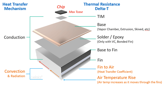
Heat Transfer Mechanisms
The Heat Sink Convection with Fins Calculator takes into account various heat transfer mechanisms, including convection, conduction, and radiation. The calculator uses correlations and models to predict the heat transfer and thermal performance of the heat sink. The calculator also accounts for fluid properties, such as density, viscosity, and specific heat capacity, to accurately predict the heat transfer and thermal performance.
Thermal Resistance and Performance
The Heat Sink Convection with Fins Calculator calculates the thermal resistance and thermal performance of the heat sink. The calculator uses thermal resistance networks and heat transfer models to predict the thermal performance of the heat sink. The calculator also provides design optimization recommendations to achieve minimum thermal resistance and maximum heat dissipation.
Input Parameters and Calculation
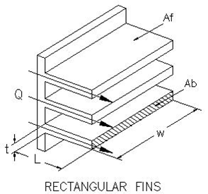
The Heat Sink Convection with Fins Calculator requires various input parameters, including fin length, fin width, fin thickness, base temperature, and ambient temperature. The calculator uses these parameters to calculate the heat transfer and thermal resistance of the heat sink. The calculation is based on empirical formulas and numerical models that take into account the heat transfer mechanisms and fluid properties.
| Parameter | Unit | Description |
|---|---|---|
| Fin Length | m | The length of the fin |
| Fin Width | m | The width of the fin |
| Fin Thickness | m | The thickness of the fin |
| Base Temperature | °C | The temperature of the base of the heat sink |
| Ambient Temperature | °C | The temperature of the surrounding air or liquid |
What is the spacing for heat sink fins for natural convection?

The spacing for heat sink fins for natural convection is a critical factor in determining the efficiency of the heat sink. The optimal spacing between fins depends on various factors, including the fluid properties, surface roughness, and temperature difference between the heat sink and the surrounding environment. A general rule of thumb is to use a fin spacing of around 3-5 times the fin thickness to achieve a good balance between heat transfer and pressure drop.
Optimal Fin Spacing for Natural Convection
The optimal fin spacing for natural convection is typically in the range of 2-10 mm, depending on the specific application and fluid properties. The spacing should be large enough to allow for adequate airflow between the fins, but not so large that it reduces the heat transfer efficiency. The following are some key factors to consider when determining the optimal fin spacing:
- Fin thickness: The fin thickness should be minimized to reduce the thermal resistance and increase the heat transfer efficiency.
- Fluid properties: The fluid properties, such as viscosity and density, play a crucial role in determining the optimal fin spacing.
- Surface roughness: The surface roughness of the fins can affect the heat transfer efficiency and should be minimized to reduce the thermal resistance.
Effect of Fin Spacing on Heat Transfer
The fin spacing has a significant impact on the heat transfer efficiency of the heat sink. As the fin spacing increases, the heat transfer efficiency also increases, but only up to a certain point. Beyond this point, further increasing the fin spacing can lead to a decrease in heat transfer efficiency due to the reduced fin surface area. The following are some key factors to consider when evaluating the effect of fin spacing on heat transfer:
- Fin surface area: The fin surface area should be maximized to increase the heat transfer efficiency.
- Fluid flow: The fluid flow between the fins should be optimized to increase the heat transfer efficiency.
- Thermal resistance: The thermal resistance of the heat sink should be minimized to increase the heat transfer efficiency.
Fin Spacing for Vertical and Horizontal Orientations
The fin spacing can vary depending on the orientation of the heat sink. For vertical orientations, the fin spacing should be smaller to reduce the pressure drop and increase the heat transfer efficiency. For horizontal orientations, the fin spacing can be larger to increase the heat transfer efficiency. The following are some key factors to consider when evaluating the fin spacing for different orientations:
- Orientation: The orientation of the heat sink can affect the heat transfer efficiency and should be considered when determining the optimal fin spacing.
- Fluid flow: The fluid flow between the fins can vary depending on the orientation and should be optimized to increase the heat transfer efficiency.
- Thermal resistance: The thermal resistance of the heat sink can vary depending on the orientation and should be minimized to increase the heat transfer efficiency.
Experimental and Numerical Studies on Fin Spacing
Several experimental and numerical studies have been conducted to investigate the effect of fin spacing on the heat transfer efficiency of heat sinks. These studies have shown that the optimal fin spacing can vary depending on the specific application and fluid properties. The following are some key findings from these studies:
- Experimental results: The experimental results have shown that the optimal fin spacing can vary depending on the fluid properties and surface roughness.
- Numerical simulations: The numerical simulations have shown that the optimal fin spacing can be predicted using computational fluid dynamics (CFD) and heat transfer models.
- Optimization techniques: The optimization techniques can be used to determine the optimal fin spacing and heat sink design for specific applications.
Applications of Optimal Fin Spacing in Heat Sinks
The optimal fin spacing has several applications in heat sinks, including electronics cooling, automotive cooling, and aerospace cooling. The following are some key applications of optimal fin spacing in heat sinks:
- Electronics cooling: The optimal fin spacing can be used to increase the heat transfer efficiency of electronics cooling systems.
- Automotive cooling: The optimal fin spacing can be used to increase the heat transfer efficiency of automotive cooling systems.
- Aerospace cooling: The optimal fin spacing can be used to increase the heat transfer efficiency of aerospace cooling systems.
What is the formula for calculating heatsinks?

The formula for calculating heatsinks involves several factors, including the thermal resistance of the heatsink, the power dissipation of the component, and the ambient temperature. The most commonly used formula is the thermal resistance formula, which is given by: Rth = (Tj - Ta) / Pd, where Rth is the thermal resistance, Tj is the junction temperature, Ta is the ambient temperature, and Pd is the power dissipation.
Introduction to Heatsink Calculation
The calculation of heatsinks is a critical aspect of thermal management in electronic systems. To calculate the heatsink required for a particular application, several factors need to be considered, including the power dissipation of the component, the ambient temperature, and the thermal resistance of the heatsink. The following are some key considerations:
- The thermal resistance of the heatsink should be as low as possible to ensure efficient heat transfer.
- The power dissipation of the component should be accurately estimated to determine the required heatsink size.
- The ambient temperature should be considered to ensure that the heatsink can operate effectively in the given environment.
Thermal Resistance Calculation
The thermal resistance of a heatsink is a measure of its ability to transfer heat from the component to the surrounding environment. The thermal resistance can be calculated using the formula: Rth = (Tj - Ta) / Pd, where Rth is the thermal resistance, Tj is the junction temperature, Ta is the ambient temperature, and Pd is the power dissipation. The following are some key factors to consider when calculating thermal resistance:
- The material properties of the heatsink, such as its thermal conductivity and specific heat capacity.
- The geometry of the heatsink, including its size and shape.
- The surface finish of the heatsink, which can affect its thermal resistance.
Power Dissipation Calculation
The power dissipation of a component is a critical factor in determining the required heatsink size. The power dissipation can be calculated using the formula: Pd = V x I, where Pd is the power dissipation, V is the voltage, and I is the current. The following are some key considerations when calculating power dissipation:
- The voltage and current ratings of the component should be accurately estimated.
- The efficiency of the component should be considered to determine the actual power dissipation.
- The operating conditions of the component, such as its temperature and humidity, should be considered.
Ambient Temperature Calculation
The ambient temperature is a critical factor in determining the required heatsink size. The ambient temperature can be calculated using the formula: Ta = Tenv + (Pd x Rth), where Ta is the ambient temperature, Tenv is the environmental temperature, Pd is the power dissipation, and Rth is the thermal resistance. The following are some key considerations when calculating ambient temperature:
- The environmental temperature should be accurately estimated.
- The thermal resistance of the heatsink should be considered to determine the actual ambient temperature.
- The airflow and convection in the surrounding environment should be considered.
Heatsink Selection and Design
The selection and design of a heatsink involve several factors, including the thermal resistance, power dissipation, and ambient temperature. The following are some key considerations when selecting and designing a heatsink:
- The thermal resistance of the heatsink should be as low as possible to ensure efficient heat transfer.
- The size and shape of the heatsink should be optimized to minimize thermal resistance and maximize heat transfer.
- The material properties of the heatsink, such as its thermal conductivity and specific heat capacity, should be considered.
What is the fin efficiency of a heat sink?
The fin efficiency of a heat sink is a measure of how effectively the fins of the heat sink are able to dissipate heat. It is defined as the ratio of the actual heat transfer rate from the fins to the maximum possible heat transfer rate if the entire fin surface were at the base temperature. The fin efficiency is an important parameter in the design of heat sinks, as it determines the overall thermal performance of the system.
Introduction to Fin Efficiency
The fin efficiency of a heat sink is a critical parameter in the design of electronic systems, as it directly affects the overall thermal management of the system. The fin efficiency is influenced by several factors, including the fin geometry, material properties, and thermal interface. A higher fin efficiency indicates that the heat sink is able to effectively dissipate heat, while a lower fin efficiency indicates that the heat sink is not performing optimally. Some key factors that affect fin efficiency include:
- Fin length: The longer the fins, the higher the fin efficiency.
- Fin thickness: Thicker fins tend to have a lower fin efficiency due to increased thermal resistance.
- Fin material: The thermal conductivity of the fin material affects the fin efficiency, with higher thermal conductivity materials resulting in higher fin efficiency.
Calculating Fin Efficiency
The fin efficiency of a heat sink can be calculated using various mathematical models, including the one-dimensional fin model and the two-dimensional fin model. These models take into account the fin geometry, thermal interface, and material properties to determine the fin efficiency. The calculation involves solving a set of differential equations that describe the heat transfer from the fins to the surrounding air or fluid. Key parameters that are used in the calculation of fin efficiency include:
- Fin dimensions: The length, width, and thickness of the fins.
- Thermal conductivity: The thermal conductivity of the fin material.
- Heat transfer coefficient: The heat transfer coefficient between the fins and the surrounding air or fluid.
Factors Affecting Fin Efficiency
Several factors can affect the fin efficiency of a heat sink, including the fin geometry, material properties, and thermal interface. The fin geometry includes the length, width, and thickness of the fins, as well as the fin spacing and fin arrangement. The material properties include the thermal conductivity and specific heat capacity of the fin material. The thermal interface includes the thermal interface material and the thermal interface resistance. Some key factors that affect fin efficiency include:
- Air flow: The air flow around the fins can significantly affect the fin efficiency.
- Fin surface roughness: A rougher fin surface can increase the fin efficiency by increasing the heat transfer coefficient.
- Fin corrosion: Corrosion of the fins can reduce the fin efficiency by increasing the thermal resistance.
Improving Fin Efficiency
There are several ways to improve the fin efficiency of a heat sink, including optimizing the fin geometry, using high thermal conductivity materials, and improving the thermal interface. Optimizing the fin geometry involves adjusting the length, width, and thickness of the fins to maximize the heat transfer area while minimizing the thermal resistance. Using high thermal conductivity materials can improve the fin efficiency by increasing the thermal conductivity of the fins. Improving the thermal interface involves using a thermal interface material with high thermal conductivity and low thermal interface resistance. Some key strategies for improving fin efficiency include:
- Using pin fins or plate fins to increase the heat transfer area.
- Using copper or aluminum as the fin material due to their high thermal conductivity.
- Applying a thermal interface material to reduce the thermal interface resistance.
Applications of Fin Efficiency
The fin efficiency of a heat sink has important implications for the thermal management of electronic systems, including computers, telecommunications equipment, and aerospace systems. A high fin efficiency is critical for ensuring the reliability and performance of these systems, as excessive heat generation can lead to component failure and system downtime. The fin efficiency is also important for energy efficiency, as a high fin efficiency can reduce the power consumption of the system by minimizing the heat transfer requirements. Some key applications of fin efficiency include:
- Computer cooling systems to dissipate heat from CPUs and GPUs.
- Telecommunications equipment to dissipate heat from power amplifiers and transceivers.
- Aerospace systems to dissipate heat from electronic components and power supplies.
How do you calculate heat loss by convection?
To calculate heat loss by convection, you need to understand the principles of convection and the factors that affect it. Convection is the transfer of heat through a fluid medium, such as air or water, due to the movement of fluid particles. The calculation of heat loss by convection involves several steps, including determining the temperature difference between the object and the surrounding fluid, the velocity of the fluid, and the characteristic length of the object.
Understanding Convection Coefficients
To calculate heat loss by convection, you need to determine the convection coefficient, which is a measure of the ability of the fluid to transfer heat. The convection coefficient depends on the velocity of the fluid, the temperature difference between the object and the fluid, and the properties of the fluid. The following are the key factors to consider when determining the convection coefficient:
- The velocity of the fluid, which affects the convection coefficient by increasing the turbulence and mixing of the fluid.
- The temperature difference between the object and the fluid, which drives the convection process.
- The properties of the fluid, such as its density, viscosity, and thermal conductivity, which affect the convection coefficient.
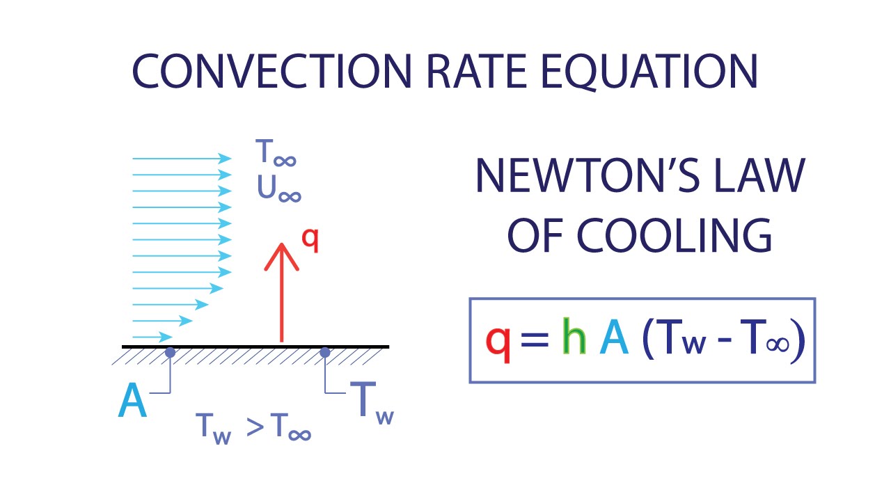
Calculating Heat Loss by Convection
The calculation of heat loss by convection involves using the convection coefficient and the temperature difference between the object and the fluid. The heat loss can be calculated using the following equation: Q = h A (T_s - T_f), where Q is the heat loss, h is the convection coefficient, A is the surface area of the object, T_s is the surface temperature of the object, and T_f is the fluid temperature. The following are the key steps to follow when calculating heat loss by convection:
- Determine the convection coefficient using the velocity of the fluid, the temperature difference between the object and the fluid, and the properties of the fluid.
- Calculate the surface area of the object and the temperature difference between the object and the fluid.
- Use the equation Q = h A (T_s - T_f) to calculate the heat loss.
Factors Affecting Convection Heat Transfer
Several factors can affect convection heat transfer, including the velocity of the fluid, the temperature difference between the object and the fluid, and the properties of the fluid. The following are the key factors to consider when analyzing convection heat transfer:
- The velocity of the fluid, which affects the turbulence and mixing of the fluid.
- The temperature difference between the object and the fluid, which drives the convection process.
- The properties of the fluid, such as its density, viscosity, and thermal conductivity, which affect the convection coefficient.
Convection Heat Transfer in Different Fluids
Convection heat transfer can occur in different fluids, including gases and liquids. The following are the key differences between convection heat transfer in gases and liquids:
- Gases have a lower density and viscosity than liquids, which affects the convection coefficient.
- Liquids have a higher thermal conductivity than gases, which affects the convection heat transfer.
- The velocity of the fluid also affects the convection heat transfer in both gases and liquids.
Applications of Convection Heat Transfer
Convection heat transfer has several applications in various fields, including engineering, architecture, and physics. The following are some of the key applications of convection heat transfer:
- Heat exchangers, which use convection heat transfer to transfer heat between two fluids.
- HVAC systems, which use convection heat transfer to heat and cool buildings.
- Electronic cooling systems, which use convection heat transfer to cool electronic components.
Frequently Asked Questions (FAQs)
What is the purpose of the Heat Sink Convection with Fins Calculator?
The Heat Sink Convection with Fins Calculator is a tool designed to calculate the heat transfer and thermal resistance of a heat sink with fins. The primary purpose of this calculator is to help engineers and designers optimize the performance of their heat sink designs, ensuring that they can efficiently dissipate heat from electronic components or other heat-generating devices. By using this calculator, users can input various parameters such as the fin length, fin width, fin thickness, heat sink base temperature, and ambient temperature, among others, to obtain accurate calculations of the heat transfer coefficient, thermal resistance, and other key performance metrics. This allows designers to iterate and refine their designs, making informed decisions about materials, geometry, and orientation to achieve optimal heat dissipation.
How does the Heat Sink Convection with Fins Calculator account for different fin configurations?
The Heat Sink Convection with Fins Calculator takes into account various fin configurations, including rectangular, triangular, and circular fins, as well as fin arrays with different spacing and orientation. The calculator uses empirical correlations and numerical models to account for the complex interactions between the fins, airflow, and heat transfer. For example, the calculator can account for the fin efficiency, which is the ratio of the actual heat transfer to the maximum possible heat transfer, as well as the pressure drop and flow resistance associated with different fin configurations. By considering these factors, the calculator provides detailed insights into the thermal performance of different fin designs, enabling users to optimize their heat sink designs for maximum efficiency and minimum size.
What are the key assumptions and limitations of the Heat Sink Convection with Fins Calculator?
The Heat Sink Convection with Fins Calculator is based on several key assumptions and limitations, which are essential to understand in order to interpret the results correctly. One of the primary assumptions is that the heat sink is operating in a steady-state condition, meaning that the heat transfer rates are constant over time. Additionally, the calculator assumes that the airflow is laminar and incompressible, and that the heat transfer is primarily driven by convection rather than radiation. The calculator also neglects certain second-order effects, such as thermal expansion and viscous dissipation, which may be significant in certain applications. Furthermore, the calculator is limited to specific geometries and boundary conditions, and may not be applicable to complex or non-standard heat sink designs. By understanding these assumptions and limitations, users can apply the calculator effectively and interpret the results with confidence.
How can the Heat Sink Convection with Fins Calculator be used to optimize heat sink designs?
The Heat Sink Convection with Fins Calculator can be used to optimize heat sink designs by iterating on various design parameters and evaluating their impact on thermal performance. For example, users can vary the fin length, fin width, and fin spacing to minimize the thermal resistance and maximize the heat transfer coefficient. The calculator can also be used to investigate the effect of different materials on thermal performance, such as copper, aluminum, or plastics, and to evaluate the trade-offs between size, weight, and cost. By using the calculator in this way, designers can rapidly explore different design options and identify the optimal solution that meets their performance, cost, and manufacturability requirements. Additionally, the calculator can be used to validate and refine existing heat sink designs, ensuring that they are optimized for maximum efficiency and reliability.
Deja una respuesta
Entradas Relacionadas