
Shaft with Keyway Torque Applied Deformation and Stress Equations and Calculator
The application of torque to a shaft with a keyway can lead to significant deformation and stress. Understanding the resulting deformation and stress is crucial for the design and analysis of mechanical systems. This article provides the necessary equations and a calculator to determine the deformation and stress in a shaft with a keyway under torque loading. The equations take into account the shaft's geometry, material properties, and the keyway dimensions, allowing engineers to accurately predict the behavior of the shaft under various loading conditions and make informed design decisions. Accurate calculations are essential for reliability.
-
Shaft with Keyway Torque Applied Deformation and Stress Equations and Calculator
- Introduction to Shaft with Keyway Torque Applied Deformation and Stress Equations
- Deformation and Stress Equations for Shaft with Keyway
- Calculator for Shaft with Keyway Torque Applied Deformation and Stress
- Applications of Shaft with Keyway Torque Applied Deformation and Stress Equations
- Limitations and Assumptions of Shaft with Keyway Torque Applied Deformation and Stress Equations
- What is the maximum torque for a keyed shaft?
- What is the formula for shaft torsion?
- How do you calculate the size of a shaft key?
-
Frequently Asked Questions (FAQs)
- What is the significance of shaft with keyway torque applied deformation and stress equations in mechanical engineering?
- How do the shaft with keyway torque applied deformation and stress equations account for the effects of keyway geometry?
- What are the limitations and assumptions of the shaft with keyway torque applied deformation and stress equations?
- How can the shaft with keyway torque applied deformation and stress equations be used in conjunction with other analysis tools to optimize mechanical system design?
Shaft with Keyway Torque Applied Deformation and Stress Equations and Calculator
The Shaft with Keyway Torque Applied Deformation and Stress Equations and Calculator is a tool used to calculate the deformation and stress of a shaft with a keyway when a torque is applied. This calculator is essential in mechanical engineering to determine! the structural integrity of the shaft and ensure it can withstand the applied loads. The calculator uses various equations to calculate the bending stress, torsional stress, and deformation of the shaft.
Introduction to Shaft with Keyway Torque Applied Deformation and Stress Equations
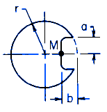
The introduction to Shaft with Keyway Torque Applied Deformation and Stress Equations is crucial in understanding the fundamentals of mechanical engineering. The shaft is a critical component in machinery, and its design must be carefully considered to ensure it can withstand the applied loads. The keyway is a slot or groove in the shaft that allows for the attachment of other components, such as gears or pulleys. When a torque is applied to the shaft, it can cause deformation and stress, which can lead to failure if not properly designed.
Deformation and Stress Equations for Shaft with Keyway
The deformation and stress equations for a shaft with a keyway are based on the beam theory and torsion theory. The bending stress (σ) can be calculated using the formula: σ = (M y) / I, where M is the bending moment, y is the distance from the neutral axis, and I is the moment of inertia. The torsional stress (τ) can be calculated using the formula: τ = (T r) / J, where T is the torque, r is the radius of the shaft, and J is the polar moment of inertia.
Calculator for Shaft with Keyway Torque Applied Deformation and Stress
The calculator for Shaft with Keyway Torque Applied Deformation and Stress is a user-friendly tool that allows engineers to input the parameters of the shaft and keyway, such as the diameter, length, and material properties. The calculator then uses the equations to calculate the deformation and stress of the shaft. The results are displayed in a table format, making it easy to interpret the results.
Applications of Shaft with Keyway Torque Applied Deformation and Stress Equations
The applications of Shaft with Keyway Torque Applied Deformation and Stress Equations are diverse, including power transmission, gearboxes, and pump systems. The equations can be used to design and analyze the performance of shafts and keyways in various industries, such as aerospace, automotive, and manufacturing.
Limitations and Assumptions of Shaft with Keyway Torque Applied Deformation and Stress Equations
The limitations and assumptions of Shaft with Keyway Torque Applied Deformation and Stress Equations must be carefully considered when using the calculator. The equations assume a linear elastic material behavior, and the calculator assumes a simple geometry. The results may not be accurate for complex geometries or non-linear material behaviors. The user must also consider the units and input values to ensure accurate results.
| Parameter | Unit | Description |
|---|---|---|
| Diameter | mm | The diameter of the shaft |
| Length | m | The length of the shaft |
| Torque | Nm | The torque applied to the shaft |
| Material | - | The material properties of the shaft |
| Deformation | mm | The deformation of the shaft |
| Stress | MPa | The stress of the shaft |
What is the maximum torque for a keyed shaft?
The maximum torque for a keyed shaft depends on various factors, including the diameter of the shaft, the material it is made of, and the type of key used. A keyed shaft is a type of shaft that has a keyway, which is a slot or groove cut into the shaft to accommodate a key. The key is a small piece of metal that is inserted into the keyway and helps to secure the shaft in place. The maximum torque that a keyed shaft can handle is determined by the torque capacity of the shaft, which is calculated based on the yield strength of the material and the cross-sectional area of the shaft.
Factors Affecting Torque Capacity
The torque capacity of a keyed shaft is affected by several factors, including the diameter of the shaft, the length of the keyway, and the type of key used. The diameter of the shaft is the most significant factor, as it determines the cross-sectional area of the shaft and therefore the torque capacity. A larger diameter shaft can handle more torque than a smaller one. The length of the keyway also affects the torque capacity, as a longer keyway can provide more resistance to torque. The type of key used can also impact the torque capacity, as different types of keys have different strengths and weaknesses. Some common types of keys include:
- Square keys, which are the most common type of key and are used for most applications
- Rectangular keys, which are used for applications that require a higher torque capacity
- Woodruff keys, which are used for applications that require a high torque capacity and a low profile
Calculating Torque Capacity
The torque capacity of a keyed shaft can be calculated using the following formula: Torque = (Yield strength x Cross-sectional area) / (Length x Factor of safety). The yield strength is the maximum stress that the material can withstand without deforming, the cross-sectional area is the area of the shaft, and the length is the length of the keyway. The factor of safety is a safety factor that is used to account for any uncertainties or variations in the calculation. For example:
- Yield strength: 500 MPa (a common value for steel)
- Cross-sectional area: 100 mm^2 (a common value for a shaft with a diameter of 10 mm)
- Length: 50 mm (a common value for a keyway)
- Factor of safety: 1.5 (a common value for a safety factor)
Types of Keys
There are several types of keys that can be used with a keyed shaft, each with its own advantages and disadvantages. Some common types of keys include:
- Spline keys, which are used for applications that require a high torque capacity and a low profile
- Involute keys, which are used for applications that require a high torque capacity and a high accuracy
- Feather keys, which are used for applications that require a low profile and a high accuracy
Keyway Design
The keyway is the slot or groove cut into the shaft to accommodate the key. The keyway design is critical to the torque capacity of the shaft, as it determines the area of the shaft that is available to resist torque. A well-designed keyway should have a smooth and consistent surface finish, and should be properly aligned with the shaft. Some common keyway designs include:
- Standard keyway, which is the most common type of keyway and is used for most applications
- Deep keyway, which is used for applications that require a higher torque capacity
- Shallow keyway, which is used for applications that require a lower torque capacity
Material Selection
The material used for the shaft and key can have a significant impact on the torque capacity of the shaft. Some common materials used for keyed shafts include:
- Steel, which is a common material for keyed shafts due to its high yield strength and toughness
- Aluminum, which is a common material for keyed shafts due to its high strength-to-weight ratio and corrosion resistance
- Brass, which is a common material for keyed shafts due to its high ductility and corrosion resistance
What is the formula for shaft torsion?

The formula for shaft torsion is given by the equation: T = (G J) / L, where T is the torque, G is the shear modulus of the material, J is the polar moment of inertia of the shaft, and L is the length of the shaft. This formula is used to calculate the torsional stress and angle of twist in a shaft under a given torque.
Understanding Shaft Torsion
Shaft torsion occurs when a twisting force is applied to a shaft, causing it to rotate and twist. The formula for shaft torsion is used to calculate the torsional stress and angle of twist in a shaft under a given torque. The key factors that affect shaft torsion are the material properties, shaft geometry, and applied torque. Some of the important factors to consider are:
- Torsional stiffness of the shaft, which depends on the shear modulus and polar moment of inertia
- Shaft diameter and length, which affect the polar moment of inertia and torsional stiffness
- Material properties, such as yield strength and ultimate strength, which determine the torsional stress and angle of twist
Calculating Torsional Stress
The torsional stress in a shaft can be calculated using the formula for shaft torsion. The torsional stress is given by the equation: τ = T r / J, where τ is the torsional stress, T is the torque, r is the radius of the shaft, and J is the polar moment of inertia. The key factors that affect torsional stress are the applied torque, shaft diameter, and material properties. Some of the important factors to consider are:
- Torque applied to the shaft, which determines the torsional stress and angle of twist
- Shaft diameter and length, which affect the polar moment of inertia and torsional stiffness
- Material properties, such as yield strength and ultimate strength, which determine the torsional stress and angle of twist
Determining Angle of Twist
The angle of twist in a shaft can be calculated using the formula for shaft torsion. The angle of twist is given by the equation: θ = T L / (G J), where θ is the angle of twist, T is the torque, L is the length of the shaft, G is the shear modulus, and J is the polar moment of inertia. The key factors that affect angle of twist are the applied torque, shaft length, and material properties. Some of the important factors to consider are:
- Torque applied to the shaft, which determines the torsional stress and angle of twist
- Shaft length, which affects the angle of twist and torsional stiffness
- Material properties, such as shear modulus and yield strength, which determine the angle of twist and torsional stress
Shaft Torsion in Real-World Applications
Shaft torsion is an important consideration in many real-world applications, such as power transmission systems, gearboxes, and axles. The formula for shaft torsion is used to design and analyze these systems, ensuring that they can withstand the applied torque and torsional stress. Some of the important factors to consider are:
- Power transmission systems, which require high torsional stiffness and low torsional stress
- Gearboxes, which require high torsional stiffness and precise control of angle of twist
- Axles, which require high torsional stiffness and low torsional stress to ensure safe and efficient operation
Mitigating the Effects of Shaft Torsion
Shaft torsion can be mitigated by using stronger materials, increasing shaft diameter, and optimizing shaft geometry. The formula for shaft torsion can be used to determine the optimal design for a shaft, taking into account the applied torque, material properties, and shaft geometry. Some of the important factors to consider are:
- Material selection, which can significantly affect the torsional stiffness and torsional stress
- Shaft diameter and length, which can be optimized to reduce torsional stress and angle of twist
- Shaft geometry, which can be optimized to reduce torsional stress and angle of twist, while maintaining high torsional stiffness
How do you calculate the size of a shaft key?

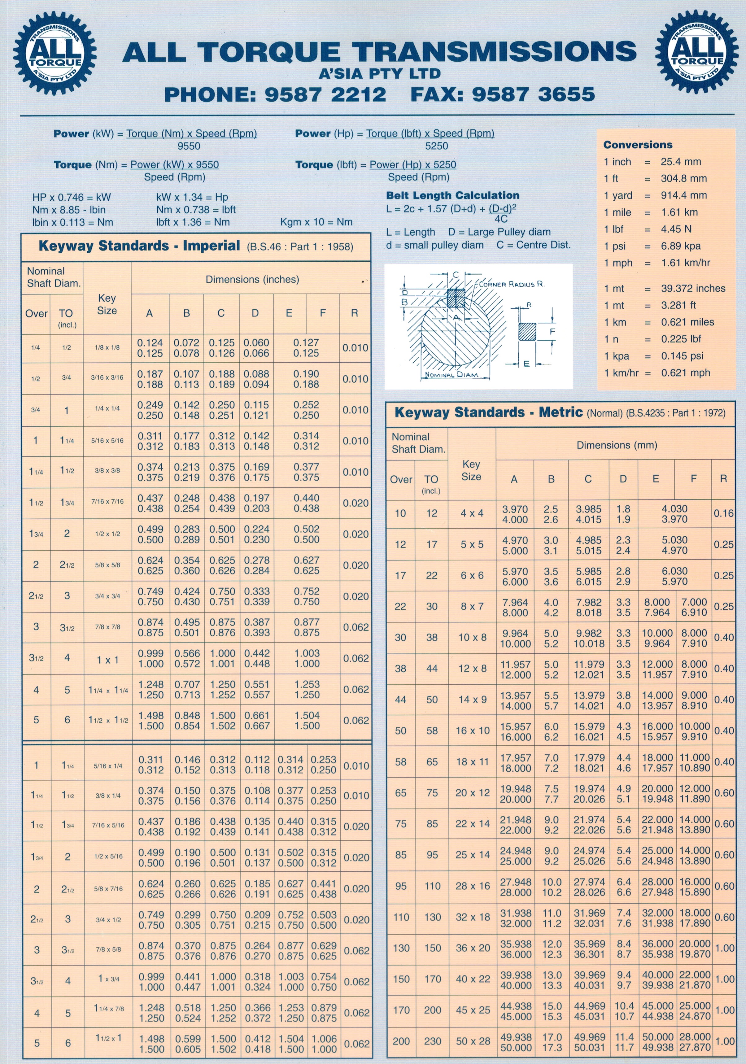
To calculate the size of a shaft key, you need to consider the diameter of the shaft, the type of key, and the application. The key size is typically determined by the American National Standards Institute (ANSI) or the International Organization for Standardization (ISO). The calculation involves determining the key width, key thickness, and key length based on the shaft diameter and the torque requirements of the application.
Understanding Shaft Key Dimensions
The dimensions of a shaft key are critical to its function. To calculate the size of a shaft key, you need to understand the key's dimensions, including its width, thickness, and length. These dimensions are determined by the shaft diameter and the application's torque requirements.
- The key width is typically between 1/4 to 1/2 of the shaft diameter.
- The key thickness is usually between 1/8 to 1/4 of the shaft diameter.
- The key length is determined by the hub length and the shaft diameter.
Calculating Key Size Based on Shaft Diameter
The shaft diameter is a critical factor in determining the size of the shaft key. The key size is typically proportional to the shaft diameter.
To calculate the key size, you can use the following formula: key width = shaft diameter x 0.25.
- Determine the shaft diameter.
- Calcule the key width using the formula.
- Verify the key thickness and key length based on the application's requirements.
Types of Shaft Keys and Their Applications
There are different types of shaft keys, including square keys, rectangular keys, and woodruff keys. Each type has its own application and installation requirements.
- Square keys are used for high-torque applications.
- Rectangular keys are used for low-torque applications.
- Woodruff keys are used for applications with limited space.
Material Selection for Shaft Keys
The material used for the shaft key is also an important consideration. The key material should be stronger than the shaft material to ensure durability and reliability.
- Steel is a common material used for shaft keys.
- Aluminum is used for lightweight applications.
- Brass is used for corrosion-resistant applications.
Installation Considerations for Shaft Keys
The installation of the shaft key is critical to its function. The key must be properly aligned and securely fastened to the shaft.
- Keyways must be accurately machined to fit the key.
- Keys must be properly seated in the keyway.
- Fasteners must be securely tightened to prevent key movement.
Frequently Asked Questions (FAQs)
What is the significance of shaft with keyway torque applied deformation and stress equations in mechanical engineering?
The shaft with keyway is a critical component in mechanical engineering, and understanding the torque applied deformation and stress equations is essential for designing and analyzing mechanical systems. The keyway is a slot or groove cut in the shaft to accommodate a key, which is a mechanical component that helps to transmit torque from one shaft to another. When torque is applied to the shaft, it can cause deformation and stress in the material, which can lead to failure if not properly designed. The equations that govern this behavior are based on the material properties, such as elastic modulus and poisson's ratio, as well as the geometric parameters of the shaft and keyway. By using these equations, engineers can predict the stress and deformation of the shaft and keyway under various loading conditions, and design the system to withstand the applied loads.
How do the shaft with keyway torque applied deformation and stress equations account for the effects of keyway geometry?
The keyway geometry plays a significant role in determining the stress and deformation of the shaft, and the equations must account for these effects. The keyway can be modeled as a stress concentration feature, which can amplify the stress in the surrounding material. The equations use geometric parameters, such as the keyway width and depth, to calculate the stress concentration factor, which is then used to predict the maximum stress in the shaft. Additionally, the equations must also account for the edge effects of the keyway, where the stress can be higher due to the sharp corners and stress concentrations. By incorporating these geometric effects, the equations can provide a more accurate prediction of the shaft behavior under torque loading.
What are the limitations and assumptions of the shaft with keyway torque applied deformation and stress equations?
The shaft with keyway torque applied deformation and stress equations are based on several assumptions and limitations, which must be understood and considered when applying these equations. One of the key assumptions is that the material behavior is linear elastic, which means that the stress and strain are related by a linear relationship. However, in reality, materials can exhibit non-linear behavior, such as plasticity and creep, which can affect the accuracy of the equations. Additionally, the equations assume that the keyway is a perfectly sharp feature, which can lead to stress concentrations and singularities. In reality, the keyway can have a finite radius and rounded edges, which can reduce the stress concentrations. By understanding these limitations and assumptions, engineers can use the equations with caution and consider additional factors that may affect the shaft behavior.
How can the shaft with keyway torque applied deformation and stress equations be used in conjunction with other analysis tools to optimize mechanical system design?
The shaft with keyway torque applied deformation and stress equations can be used in conjunction with other analysis tools, such as finite element analysis (FEA) and computational fluid dynamics (CFD), to optimize mechanical system design. By using these equations to predict the stress and deformation of the shaft, engineers can identify potential failure modes and optimize the design to minimize stress concentrations and maximize the system performance. Additionally, the equations can be used to validate the results of FEA and CFD simulations, which can provide a more detailed understanding of the system behavior. By combining these analysis tools, engineers can develop a more comprehensive understanding of the mechanical system and optimize the design to meet the performance requirements. Furthermore, the equations can be used to inform the design of experiments and testing protocols, which can help to validate the analysis results and improve the overall system design.
Deja una respuesta
Entradas Relacionadas