
Multiple weights outside fulcrum lever equations and calculators
The concept of multiple weights outside a fulcrum introduces complexity to lever equations, requiring a deeper understanding of physics and mathematics. When dealing with multiple weights, calculating the resulting force and motion becomes more intricate. To simplify these calculations, specialized equations and calculators have been developed, allowing for accurate predictions of lever behavior under various load conditions. This article will explore the equations and tools used to analyze and calculate the effects of multiple weights outside a fulcrum, providing insight into the underlying mechanics and mathematical principles. Lever equations and calculators are crucial in this context.
- Understanding Multiple Weights Outside Fulcrum Lever Equations and Calculators
- How do you calculate lever and fulcrum?
- How to calculate length from fulcrum to resistance force?
- What is the formula for the second order lever?
- What is the equation for balance a lever?
-
Frequently Asked Questions (FAQs)
- What is the concept of multiple weights outside fulcrum lever equations and calculators?
- How do multiple weights outside fulcrum lever equations and calculators work in real-world applications?
- What are the benefits of using multiple weights outside fulcrum lever equations and calculators in problem-solving?
- How can multiple weights outside fulcrum lever equations and calculators be used to teach and learn physics and engineering concepts?
Understanding Multiple Weights Outside Fulcrum Lever Equations and Calculators
The concept of multiple weights outside a fulcrum in lever systems is a fundamental aspect of physics and engineering. It involves the application of forces and torques to achieve equilibrium or to create motion. In this context, lever equations and calculators play a crucial role in determining the behavior of such systems.
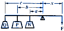
When dealing with multiple weights outside a fulcrum, the principle of moments must be considered. This principle states that the clockwise moments must equal the counterclockwise moments for the system to be in equilibrium. The calculation of these moments involves the product of the force applied and the distance from the fulcrum to the point where the force is applied.
Basic Concepts of Lever Systems
Lever systems are comprised of a beam, a fulcrum, and weights or forces applied at various points. The fulcrum acts as the pivot point around which the beam rotates. The weights or forces applied to the beam create moments that can either be clockwise or counterclockwise. Understanding these basic concepts is essential for applying lever equations and using calculators to solve problems.
Application of Lever Equations
The application of lever equations involves calculating the moments created by the weights or forces. The equation for the moment is given by M = F d, where M is the moment, F is the force, and d is the distance from the fulcrum to the point where the force is applied. By summing the clockwise moments and the counterclockwise moments, one can determine if the system is in equilibrium.
Use of Calculators in Solving Lever Problems
Calculators can greatly simplify the process of solving lever problems, especially when dealing with multiple weights outside the fulcrum. By inputting the values of the forces, distances, and moments, one can quickly determine if the system is in equilibrium or calculate the force required to achieve equilibrium. Moreover, calculators can help in visualizing the system and understanding the effects of changing forces or distances.
Complexity of Multiple Weights Outside Fulcrum
When multiple weights are placed outside the fulcrum, the system becomes more complex. The principle of superposition must be applied, where the moments created by each weight are calculated separately and then summed to find the total moment. This requires careful consideration of the direction of each force and the distance from the fulcrum to accurately calculate the moments.
Real-World Applications of Lever Systems
Lever systems with multiple weights outside the fulcrum have numerous real-world applications. They are found in machinery, mechanisms, and structures where the application of forces and moments is critical. Understanding the lever equations and using calculators to solve problems can help in designing and optimizing these systems for efficiency and safety.
| Concept | Description |
|---|---|
| Forces | Pushes or pulls that cause an object to change its state of motion |
| Torques | Rotational forces that cause an object to rotate |
| Lever Equations | Mathematical expressions used to calculate the behavior of lever systems |
| Calculators | Tools used to simplify and solve lever problems |
| Principle of Moments | The principle that the sum of clockwise moments must equal the sum of counterclockwise moments for a system to be in equilibrium |
How do you calculate lever and fulcrum?

To calculate lever and fulcrum, you need to understand the basic principles of mechanics and physics. A lever is a simple machine that consists of a rigid bar or beam that pivots around a fixed point called the fulcrum. The fulcrum is the point where the lever rotates or pivots. The calculation of lever and fulcrum involves determining the torque or rotational force that is applied to the lever.
Understanding the Concept of Lever and Fulcrum
The concept of lever and fulcrum is based on the principle of conservation of energy. When a force is applied to one end of the lever, it causes a rotation or torque around the fulcrum. The distance from the fulcrum to the point where the force is applied is called the lever arm. The calculation of lever and fulcrum involves determining the length of the lever arm and the magnitude of the force applied.
- The law of moments states that the torque or rotational force is equal to the force multiplied by the distance from the fulcrum to the point where the force is applied.
- The principle of leverage states that the ratio of the input force to the output force is equal to the ratio of the length of the input arm to the length of the output arm.
- The fulcrum is the point where the lever pivots or rotates, and it is the point where the torque or rotational force is applied.
Calculating the Lever Arm and Fulcrum
To calculate the lever arm and fulcrum, you need to determine the length of the lever arm and the magnitude of the force applied. The lever arm is the distance from the fulcrum to the point where the force is applied. The calculation of the lever arm involves determining the angle of the lever and the distance from the fulcrum to the point where the force is applied.
- The length of the lever arm can be calculated using the law of cosines, which states that the square of the length of the lever arm is equal to the sum of the squares of the lengths of the two sides of the triangle formed by the lever and the fulcrum.
- The magnitude of the force applied can be calculated using the principle of superposition, which states that the resultant force is equal to the sum of the individual forces applied to the lever.
- The fulcrum can be calculated using the principle of equilibrium, which states that the sum of the torques or rotational forces acting on the lever is equal to zero.
Determining the Type of Lever
There are three types of levers: first-class levers, second-class levers, and third-class levers. The type of lever depends on the location of the fulcrum and the direction of the force applied.
- A first-class lever has the fulcrum located between the input force and the output force.
- A second-class lever has the fulcrum located at one end of the lever, and the input force and output force are applied at the other end.
- A third-class lever has the fulcrum located at one end of the lever, and the input force is applied at the other end, while the output force is applied between the fulcrum and the input force.
Calculating the Mechanical Advantage
The mechanical advantage of a lever is the ratio of the output force to the input force. The mechanical advantage can be calculated using the principle of leverage, which states that the ratio of the input force to the output force is equal to the ratio of the length of the input arm to the length of the output arm.
- The mechanical advantage can be calculated using the formula: mechanical advantage = output force / input force.
- The mechanical advantage can also be calculated using the formula: mechanical advantage = length of output arm / length of input arm.
- The mechanical advantage is an important factor in determining the efficiency of a lever, as it determines the amount of force that can be applied to the output.
Applying the Principles of Lever and Fulcrum
The principles of lever and fulcrum have many practical applications in engineering and physics. The calculation of lever and fulcrum involves determining the torque or rotational force that is applied to the lever, as well as the mechanical advantage of the lever.
- The principle of leverage is used in the design of machines and mechanisms, such as gears and pulleys.
- The principle of fulcrum is used in the design of bridges and buildings, where the torque or rotational force must be balanced.
- The calculation of lever and fulcrum is an important factor in determining the stability and efficiency of a system, as it determines the amount of force that can be applied to the output.
How to calculate length from fulcrum to resistance force?

To calculate the length from the fulcrum to the resistance force, you need to understand the concept of moments and torque. The fulcrum is the pivot point of a lever, and the resistance force is the force that opposes the movement of the lever. The length from the fulcrum to the resistance force is crucial in determining the mechanical advantage of the lever.
Understanding the Concept of Moments
The concept of moments is essential in calculating the length from the fulcrum to the resistance force. A moment is a measure of the rotational force that causes an object to rotate around a pivot point. The moment is calculated by multiplying the force by the distance from the pivot point to the point where the force is applied. To calculate the length from the fulcrum to the resistance force, you need to understand how moments are calculated and how they relate to the torque applied to the lever.
- Identify the fulcrum and the resistance force in the system.
- Determine the distance from the fulcrum to the point where the resistance force is applied.
- Calculate the moment of the resistance force by multiplying the force by the distance.
Calculating the Mechanical Advantage
The mechanical advantage of a lever is a measure of the force amplification that occurs when a force is applied to the lever. The mechanical advantage is calculated by dividing the output force by the input force. To calculate the length from the fulcrum to the resistance force, you need to understand how the mechanical advantage is related to the length of the lever.
- Calculate the input force and the output force.
- Determine the mechanical advantage by dividing the output force by the input force.
- Use the mechanical advantage to calculate the length from the fulcrum to the resistance force.
Applying the Concept of Torque
Torque is a measure of the rotational force that causes an object to rotate around a pivot point. The torque is calculated by multiplying the force by the distance from the pivot point to the point where the force is applied. To calculate the length from the fulcrum to the resistance force, you need to understand how torque is related to the moment of the resistance force.
- Calculate the torque applied to the lever.
- Determine the distance from the fulcrum to the point where the torque is applied.
- Use the torque to calculate the length from the fulcrum to the resistance force.
Using the Law of Moments
The Law of Moments states that the sum of the moments of the forces acting on a lever is equal to zero. This law can be used to calculate the length from the fulcrum to the resistance force. To apply the Law of Moments, you need to identify the forces acting on the lever and calculate their moments.
- Identify the forces acting on the lever.
- Calculate the moments of the forces.
- Use the Law of Moments to calculate the length from the fulcrum to the resistance force.
Considering the Types of Levers
There are three types of levers: first-class, second-class, and third-class. Each type of lever has a different fulcrum and resistance force configuration. To calculate the length from the fulcrum to the resistance force, you need to understand the characteristics of each type of lever.
- Identify the type of lever.
- Determine the fulcrum and resistance force configuration.
- Use the characteristics of the lever to calculate the length from the fulcrum to the resistance force, using mathematical models and physical principles.
What is the formula for the second order lever?
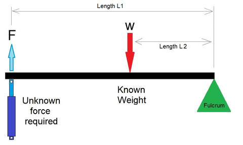
The formula for the second order lever is Mechanical Advantage (MA) = Effort Arm (EA) / Load Arm (LA) = Effort (E) / Load (L). This formula is used to calculate the mechanical advantage of a second order lever, which is a type of simple machine that consists of a fulcrum, a load, and an effort.
What is a Second Order Lever?
A second order lever is a type of simple machine that has the fulcrum at one end, the effort at the other end, and the load suspended between the two. This type of lever is commonly used in machines and mechanisms to gain a mechanical advantage. The formula for the second order lever is used to calculate the mechanical advantage, which is the ratio of the effort to the load.
- The effort is the force applied to the lever to lift the load.
- The load is the weight or force that is being lifted by the lever.
- The fulcrum is the pivot point of the lever, which remains stationary while the lever is in motion.
How Does a Second Order Lever Work?
A second order lever works by using the fulcrum as a pivot point to change the direction of the effort force. The effort force is applied to one end of the lever, and the load is suspended from the other end. As the effort force is applied, the lever pivots around the fulcrum, lifting the load. The mechanical advantage of the lever is determined by the ratio of the effort arm to the load arm.
- The effort arm is the distance from the fulcrum to the point where the effort force is applied.
- The load arm is the distance from the fulcrum to the point where the load is suspended.
- The mechanical advantage is the ratio of the effort arm to the load arm.
What is the Mechanical Advantage of a Second Order Lever?
The mechanical advantage of a second order lever is the ratio of the effort to the load. This is calculated using the formula Mechanical Advantage (MA) = Effort Arm (EA) / Load Arm (LA) = Effort (E) / Load (L). The mechanical advantage of a second order lever can be greater than, less than, or equal to 1, depending on the ratio of the effort arm to the load arm.
- If the effort arm is longer than the load arm, the mechanical advantage is greater than 1.
- If the effort arm is shorter than the load arm, the mechanical advantage is less than 1.
- If the effort arm is equal to the load arm, the mechanical advantage is equal to 1.
What are the Advantages of a Second Order Lever?
The advantages of a second order lever include the ability to gain a mechanical advantage, which can be used to lift heavy loads with less effort. Additionally, second order levers are often used in machines and mechanisms to change the direction of the effort force, making it easier to perform tasks such as lifting and moving heavy objects.
- The mechanical advantage of a second order lever can be used to lift heavy loads with less effort.
- Second order levers are often used in machines and mechanisms to change the direction of the effort force.
- The fulcrum of a second order lever remains stationary while the lever is in motion, making it easier to control the load.
What are the Disadvantages of a Second Order Lever?
The disadvantages of a second order lever include the fact that the effort force must be applied over a greater distance than the load is lifted, which can make it more difficult to use. Additionally, second order levers can be unstable if the fulcrum is not properly secured, which can cause the load to fall or the lever to break.
- The effort force must be applied over a greater distance than the load is lifted, which can make it more difficult to use.
- Second order levers can be unstable if the fulcrum is not properly secured.
- The mechanical advantage of a second order lever can be affected by the friction between the fulcrum and the lever.
What is the equation for balance a lever?
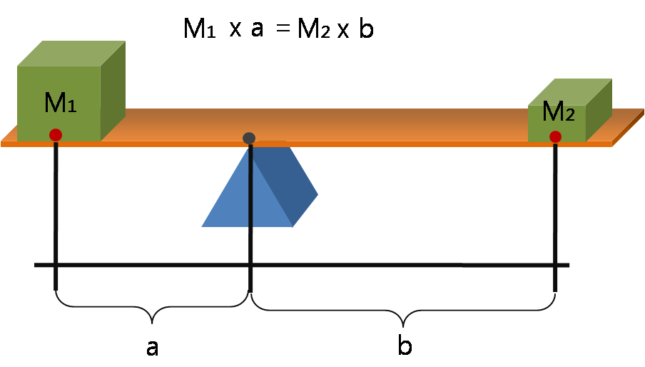
The equation for balancing a lever is based on the principle of torque and equilibrium. The equation is: Force x Distance = Force x Distance, or F1 x d1 = F2 x d2, where F1 and F2 are the forces applied to the lever, and d1 and d2 are the distances from the fulcrum to the points where the forces are applied.
Understanding the Concept of Torque
The concept of torque is crucial in understanding the equation for balancing a lever. Torque is a measure of the rotational force that causes an object to rotate or turn. In the context of a lever, torque is the product of the force applied and the distance from the fulcrum to the point where the force is applied. The equation for torque is: Torque = Force x Distance. Some key points to consider when understanding torque are:
- The direction of the force applied to the lever can affect the torque, with forces applied in a clockwise direction producing a positive torque and forces applied in a counterclockwise direction producing a negative torque.
- The distance from the fulcrum to the point where the force is applied is also critical, as a greater distance results in a greater torque.
- The magnitude of the force applied to the lever also affects the torque, with a greater force resulting in a greater torque.
Applying the Equation to Real-World Scenarios
The equation for balancing a lever has numerous practical applications in real-world scenarios, such as in construction, engineering, and physics. By understanding the equation, individuals can design and build efficient systems that minimize energy and effort. Some examples of applying the equation to real-world scenarios include:
- Designing a seesaw that is balanced and safe for children to play on.
- Building a bridge that can support a heavy load without collapsing.
- Creating a machine that can lift heavy objects with minimal effort.
The Importance of Fulcrum Placement
The placement of the fulcrum is critical in balancing a lever, as it affects the equilibrium of the system. The fulcrum is the point around which the lever pivots, and its placement determines the ratio of the forces applied to the lever. Some key points to consider when placing the fulcrum are:
- The position of the fulcrum affects the balance of the lever, with a fulcrum placed closer to one end resulting in a greater force required to balance the lever.
- The stability of the fulcrum is also important, as a fulcrum that is not stable can cause the lever to oscillate or become unbalanced.
- The material used to construct the fulcrum can also affect its performance, with a fulcrum made of a strong and durable material providing better support and stability.
Common Mistakes to Avoid When Balancing a Lever
There are several common mistakes that individuals make when balancing a lever, including ignoring the equation for torque and miscalculating the forces and distances involved. Some key points to consider when avoiding these mistakes are:
- Double-checking the calculations to ensure that the forces and distances are correct.
- Using a systematic approach to solve the problem, rather than relying on intuition or guesswork.
- Considering the friction and resistance that can affect the motion of the lever, and taking steps to minimize these factors.
Real-World Examples of Levers in Action
There are many real-world examples of levers in action, including simple machines such as scissors, hammers, and wheels. These machines use the principle of leverage to amplify the force applied, making them more efficient and effective. Some examples of levers in action include:
- A car jack that uses a hydraulic system to lift a car with minimal effort.
- A pair of pliers that use a mechanical advantage to open and close around an object.
- A see-saw that uses a fulcrum to balance the weight of two individuals.
Frequently Asked Questions (FAQs)
What is the concept of multiple weights outside fulcrum lever equations and calculators?
The concept of multiple weights outside fulcrum lever equations and calculators refers to the mathematical representation of a system where multiple weights are applied to a lever at different distances from the fulcrum. This system is based on the principle of equilibrium, where the sum of the clockwise moments is equal to the sum of the counterclockwise moments. The lever equation is used to calculate the weight or force required to balance the system, taking into account the distance from the fulcrum to each weight. Calculators can be used to simplify the calculation process, especially when dealing with complex systems involving multiple weights and fulcrums.
How do multiple weights outside fulcrum lever equations and calculators work in real-world applications?
In real-world applications, multiple weights outside fulcrum lever equations and calculators are used in various fields such as physics, engineering, and architecture. For example, in the design of bridges, cranes, and elevators, the calculation of weight and force distributions is crucial to ensure stability and safety. The lever equation is used to determine the weight or force required to balance the system, taking into account the distance from the fulcrum to each weight. Calculators can be used to simplify the calculation process, allowing designers and engineers to quickly and accurately determine the required weight or force. Additionally, the concept of multiple weights outside fulcrum can be applied to simple machines such as see-saws and wheelbarrows, where the calculation of weight and force distributions is essential to ensure efficient and safe operation.
What are the benefits of using multiple weights outside fulcrum lever equations and calculators in problem-solving?
The use of multiple weights outside fulcrum lever equations and calculators in problem-solving offers several benefits, including increased accuracy, simplified calculations, and improved understanding of the underlying physical principles. By using calculators to simplify the calculation process, problem-solvers can quickly and accurately determine the required weight or force to balance a system. Additionally, the lever equation provides a clear and concise representation of the system, allowing problem-solvers to visualize and analyze the relationships between the weights, forces, and distances involved. Furthermore, the concept of multiple weights outside fulcrum can be used to model and simulate real-world systems, allowing problem-solvers to predict and optimize the behavior of complex systems.
How can multiple weights outside fulcrum lever equations and calculators be used to teach and learn physics and engineering concepts?
Multiple weights outside fulcrum lever equations and calculators can be used to teach and learn physics and engineering concepts in a variety of ways. For example, interactive simulations can be used to model and simulate real-world systems, allowing students to explore and investigate the relationships between weights, forces, and distances. Additionally, calculators can be used to simplify the calculation process, allowing students to focus on the underlying physical principles rather than getting bogged down in complex calculations. The lever equation provides a clear and concise representation of the system, making it easier for students to understand and apply the concepts to real-world problems. Furthermore, the concept of multiple weights outside fulcrum can be used to illustrate and reinforce key concepts such as equilibrium, momentum, and energy, making it a valuable tool for teaching and learning physics and engineering.
Deja una respuesta
Entradas Relacionadas