
Press Fit Engineering and Design Calculator

The Press Fit Engineering and Design Calculator is a valuable tool for engineers and designers working with press fit technology. Press fit, also known as interference fit, is a mechanical attachment method where a pin or shaft is inserted into a hole with a slightly smaller diameter, creating a secure and reliable connection. This calculator helps users determine the optimal dimensions and tolerances for press fit applications, ensuring a strong and lasting joint. By streamlining the design process, the calculator saves time and reduces errors, making it an essential resource for professionals in the field.
- Press Fit Engineering and Design Calculator: A Comprehensive Tool for Engineers
- How to calculate press fit?
- How do you measure press fit?
- How big should a hole be for a press fit?
-
Frequently Asked Questions (FAQs)
- What is the Press Fit Engineering and Design Calculator and how does it work?
- What are the key benefits of using the Press Fit Engineering and Design Calculator?
- How does the Press Fit Engineering and Design Calculator handle complex material properties and geometric tolerances?
- Can the Press Fit Engineering and Design Calculator be used for a wide range of applications, including aerospace, automotive, and industrial equipment?
Press Fit Engineering and Design Calculator: A Comprehensive Tool for Engineers
The Press Fit Engineering and Design Calculator is a specialized tool used by engineers to design and optimize press fit assemblies. This calculator takes into account various factors such as material properties, geomety, and tolerances to determine the optimal interference fit and clearance for a given application. By using this calculator, engineers can ensure that their designs meet the required specifications and standards, while also minimizing costs and production time.
Introduction to Press Fit Engineering and Design
Press fit engineering and design involves the creation of assemblies where two or more parts are joined together using a press fit technique. This technique involves inserting one part into another with a slight interference fit, which creates a secure and precise connection. The Press Fit Engineering and Design Calculator is an essential tool in this process, as it helps engineers to determine the optimal dimensions and tolerances for the parts involved.
Key Factors in Press Fit Design
When designing a press fit assembly, there are several key factors that must be considered. These include the material properties of the parts involved, such as their elastic modulus and poisson's ratio. The geomety of the parts is also critical, including the diameter, length, and surface finish. Additionally, the tolerances of the parts must be carefully controlled to ensure a precise and secure connection.
Benefits of Using a Press Fit Calculator
Using a Press Fit Engineering and Design Calculator offers several benefits to engineers. These include increased accuracy and precision, as well as reduced production costs and time. The calculator can also help to minimize errors and improve quality, by ensuring that the designed assembly meets the required specifications and standards.
How to Use a Press Fit Calculator
To use a Press Fit Engineering and Design Calculator, engineers must input various parameters such as the material properties, geomety, and tolerances of the parts involved. The calculator will then output the optimal interference fit and clearance for the assembly, as well as other relevant design parameters. The calculator can be used to design a wide range of press fit assemblies, from simple to complex.
Common Applications of Press Fit Assemblies
Press fit assemblies are used in a wide range of applications, including automotive, aerospace, and industrial. They are particularly useful in situations where a secure and precise connection is required, such as in gearboxes, bearings, and shafts. The following table shows some common applications of press fit assemblies:
| Application | Industry | Key Features |
|---|---|---|
| Gearboxes | Automotive | High torque, high speed |
| Bearings | Aerospace | High precision, low friction |
| Shafts | Industrial | High strength, high durability |
How to calculate press fit?

To calculate press fit, it is essential to understand the concept of interference fit, which is the difference between the outer diameter of the shaft and the inner diameter of the hole. The interference fit is critical in determining the press fit force required to assemble two parts together. The calculation involves determining the interference value, which is the difference between the shaft diameter and the hole diameter. This value is then used to calculate the press fit force using various formulas, such as the Lame formula or the Shigley formula.
Understanding Press Fit Concepts
To calculate press fit, it is crucial to understand the concepts involved, including interference fit, clearance fit, and transition fit. The interference fit is the most common type of press fit, where the shaft diameter is larger than the hole diameter, resulting in an interference value. The calculation of press fit involves determining the interference value and using it to calculate the press fit force. Some key points to consider are:
- Interference fit is the most common type of press fit.
- Clearance fit is used when the shaft diameter is smaller than the hole diameter.
- Transition fit is used when the shaft diameter is close to the hole diameter.
Calculating Interference Fit
The calculation of interference fit involves determining the interference value, which is the difference between the shaft diameter and the hole diameter. The interference value is critical in determining the press fit force required to assemble two parts together. The calculation of interference fit can be done using various formulas, such as the Lame formula or the Shigley formula. Some key points to consider are:
- Interference value is the difference between the shaft diameter and the hole diameter.
- Lame formula is used to calculate the interference fit for a cylindrical shape.
- Shigley formula is used to calculate the interference fit for a spherical shape.
Applying Press Fit Formulas
The calculation of press fit involves applying various formulas, such as the Lame formula or the Shigley formula. These formulas use the interference value to calculate the press fit force required to assemble two parts together. The Lame formula is used for cylindrical shapes, while the Shigley formula is used for spherical shapes. Some key points to consider are:
- Lame formula is used for cylindrical shapes.
- Shigley formula is used for spherical shapes.
- Press fit force is calculated using the interference value and the formula.
Determining Press Fit Force
The press fit force is critical in determining the assembly process of two parts together. The press fit force is calculated using the interference value and various formulas, such as the Lame formula or the Shigley formula. The press fit force is essential in ensuring that the parts are properly assembled and that the assembly is secure. Some key points to consider are:
- Press fit force is calculated using the interference value and the formula.
- Assembly process is critical in determining the press fit force.
- Secure assembly is essential in ensuring that the parts are properly assembled.
Considering Material Properties
The material properties of the parts being assembled are critical in determining the press fit force. The material properties, such as young's modulus and poisson's ratio, affect the interference value and the press fit force. The material properties must be considered when calculating the press fit force to ensure that the assembly is secure. Some key points to consider are:
- Young's modulus affects the interference value and the press fit force.
- Poisson's ratio affects the interference value and the press fit force.
- Material properties must be considered when calculating the press fit force.
How do you measure press fit?
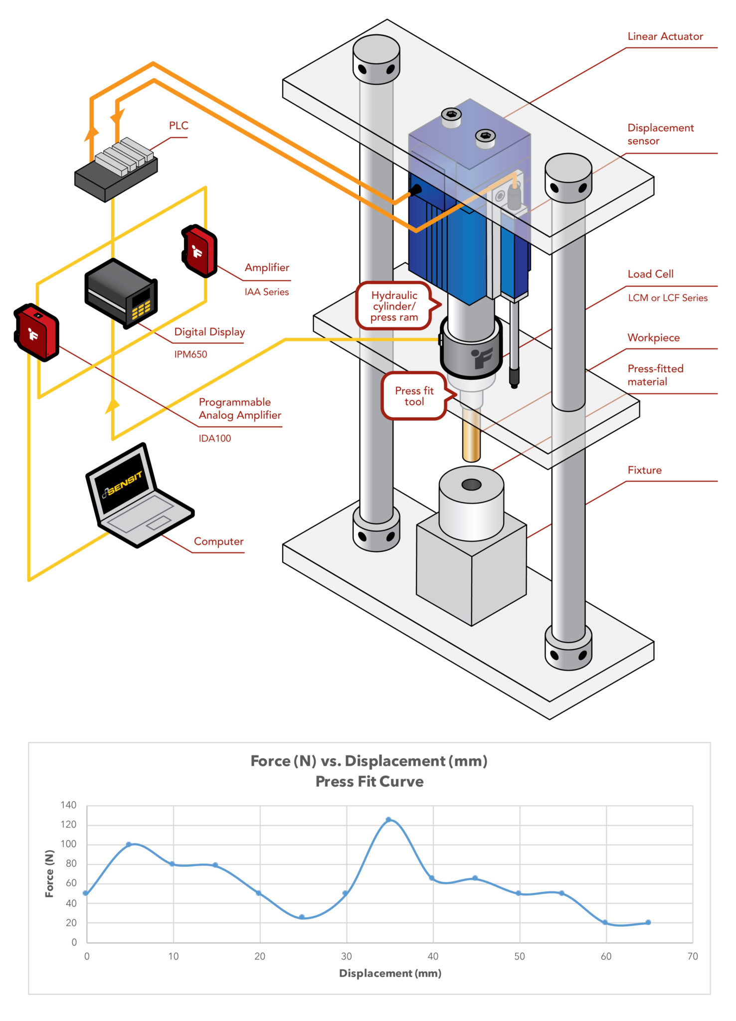
Measuring press fit involves determining the amount of force required to assemble or disassemble two parts that are designed to fit together with a specific amount of interference. This can be done using various methods, including calculating the design tolerances and clearances of the parts, as well as using specialized equipment such as force gauges or press fit testers.
Understanding Press Fit Tolerances
To measure press fit, it's essential to understand the tolerances and clearances involved in the design of the parts. This includes the diametral interference, which is the difference between the outer diameter of the shaft and the inner diameter of the hub. A larger diametral interference will result in a tighter press fit, requiring more force to assemble or disassemble the parts. The following steps can be taken to understand press fit tolerances:
- Calculate the diametral interference by subtracting the inner diameter of the hub from the outer diameter of the shaft.
- Determine the design tolerances for the parts, including the maximum and minimum permissible diameters.
- Use Dimensional Analysis to calculate the clearance between the parts and determine the press fit requirements.
Using Force Gauges to Measure Press Fit
Force gauges can be used to measure the amount of force required to assemble or disassemble two parts with a press fit. This involves attaching the force gauge to the shaft or hub and measuring the force applied to the part as it is pressed into or out of the other part. The following steps can be taken to use force gauges:
- Attach the force gauge to the shaft or hub and set the zero point.
- Apply a gradual and consistent force to the part, measuring the force required to assemble or disassemble the parts.
- Record the maximum force required to assemble or disassemble the parts, which will indicate the press fit requirements.
Calculating Press Fit Requirements
To calculate the press fit requirements, it's essential to understand the design tolerances and clearances involved in the design of the parts. This includes calculating the diametral interference and determining the design tolerances for the parts. The following steps can be taken to calculate press fit requirements:
- Calculate the diametral interference by subtracting the inner diameter of the hub from the outer diameter of the shaft.
- Determine the design tolerances for the parts, including the maximum and minimum permissible diameters.
- Use Dimensional Analysis to calculate the clearance between the parts and determine the press fit requirements.
Design Considerations for Press Fit
When designing parts with a press fit, it's essential to consider the design tolerances and clearances involved in the design of the parts. This includes calculating the diametral interference and determining the design tolerances for the parts. The following steps can be taken to consider design:
- Calculate the diametral interference by subtracting the inner diameter of the hub from the outer diameter of the shaft.
- Determine the design tolerances for the parts, including the maximum and minimum permissible diameters.
- Use Computer-Aided Design (CAD) software to model the parts and determine the press fit requirements.
Best Practices for Measuring Press Fit
To ensure accurate press fit measurements, it's essential to follow best practices when measuring the parts. This includes using precision measuring instruments, such as micrometers or calipers, and ensuring that the parts are clean and dry before measurement. The following steps can be taken to follow best practices:
- Use precision measuring instruments, such as micrometers or calipers, to measure the parts.
- Ensure that the parts are clean and dry before measurement to prevent contamination or corrosion.
- Follow the manufacturer's instructions for the measuring instruments and press fit testers to ensure accurate measurements.
How big should a hole be for a press fit?
The size of a hole for a press fit depends on several factors, including the type of material, the desired level of interference, and the tolerance of the components involved. In general, the hole should be slightly smaller than the diameter of the part to be inserted, allowing for a secure fit without being too difficult to assemble. The exact size of the hole will depend on the specific application and the requirements of the design.
Types of Press Fits
There are several types of press fits, including slip fits, transition fits, and interference fits. Each type of fit has its own specific requirements for the size of the hole. For example, a slip fit requires a hole that is slightly larger than the diameter of the part, while an interference fit requires a hole that is slightly smaller. Some key considerations for determining the size of the hole include:
- Material properties: The type of material and its elasticity will affect the size of the hole required for a press fit.
- Component design: The geometry and tolerance of the components involved will impact the size of the hole.
- Assembly requirements: The force required to assemble the components will influence the size of the hole.
Calculating Hole Size
To calculate the size of the hole for a press fit, you need to consider the diameter of the part to be inserted, as well as the tolerance and interference required. The interference can be calculated using formulas that take into account the material properties and component design. Some key factors to consider when calculating the hole size include:
- Diameter of the part: The diameter of the part to be inserted will determine the minimum size of the hole.
- Tolerance of the components: The tolerance of the components will impact the size of the hole required for a secure fit.
- Interference required: The level of interference required will affect the size of the hole, with higher interference requiring a smaller hole.
Press Fit Tolerances
The tolerance of the components involved will impact the size of the hole required for a press fit. Tight tolerances will require a smaller hole, while loose tolerances will allow for a larger hole. Some key considerations for determining the tolerance include:
- Component design: The geometry and material properties of the components will impact the tolerance required.
- Assembly requirements: The force required to assemble the components will influence the tolerance.
- Manufacturing process: The processing and manufacturing methods used will affect the tolerance of the components.
Materials and Press Fits
The type of material used will impact the size of the hole required for a press fit. Ductile materials will require a smaller hole than brittle materials, due to their ability to deform without breaking. Some key considerations for determining the size of the hole based on material include:
- Material properties: The elasticity and strength of the material will affect the size of the hole required.
- Component design: The geometry and tolerance of the components will impact the size of the hole required.
- Assembly requirements: The force required to assemble the components will influence the size of the hole.
Design Considerations
The design of the components involved will impact the size of the hole required for a press fit. Complex geometries and tight tolerances will require a smaller hole, while simple geometries and loose tolerances will allow for a larger hole. Some key considerations for determining the size of the hole based on design include:
- Component geometry: The shape and size of the components will impact the size of the hole required.
- Assembly requirements: The force required to assemble the components will influence the size of the hole.
- Manufacturing process: The processing and manufacturing methods used will affect the size of the hole required.
Frequently Asked Questions (FAQs)
What is the Press Fit Engineering and Design Calculator and how does it work?
The Press Fit Engineering and Design Calculator is a software tool designed to help engineers and designers calculate the interference fit between two parts, typically a shaft and a hub, in a press fit assembly. This calculator uses complex algorithms and mathematical models to determine the optimal interference fit for a given application, taking into account factors such as the material properties, geometric tolerances, and assembly conditions. By using this calculator, engineers can optimize their designs and ensure a reliable and consistent press fit assembly.
What are the key benefits of using the Press Fit Engineering and Design Calculator?
The Press Fit Engineering and Design Calculator offers several key benefits to engineers and designers, including increased accuracy and reduced uncertainty in their designs. By using this calculator, engineers can minimize the risk of assembly failures and reduce the need for physical prototypes, which can be time-consuming and costly. Additionally, the calculator can help engineers to optimize their designs for specific applications, such as high-speed or high-load conditions, and to identify potential issues before they become major problems. Overall, the Press Fit Engineering and Design Calculator is a valuable tool for anyone involved in the design and manufacture of press fit assemblies.
How does the Press Fit Engineering and Design Calculator handle complex material properties and geometric tolerances?
The Press Fit Engineering and Design Calculator is designed to handle complex material properties and geometric tolerances with ease. The calculator uses advanced mathematical models to account for the nonlinear behavior of materials and the effects of tolerances on the assembly. The calculator can also handle multiple materials and complex geometries, making it a powerful tool for engineers and designers working on a wide range of applications. Additionally, the calculator includes a comprehensive database of material properties and geometric tolerances, which can be easily updated and customized to meet the specific needs of the user.
Can the Press Fit Engineering and Design Calculator be used for a wide range of applications, including aerospace, automotive, and industrial equipment?
Yes, the Press Fit Engineering and Design Calculator is a versatile tool that can be used for a wide range of applications, including aerospace, automotive, and industrial equipment. The calculator is designed to be application-independent, meaning that it can be used to analyze and optimize press fit assemblies for any industry or application. The calculator's advanced algorithms and mathematical models make it an ideal tool for engineers and designers working on high-performance or high-reliability applications, where the integrity of the assembly is critical. Whether you are designing a mission-critical system for the aerospace industry or a high-volume production line for the automotive industry, the Press Fit Engineering and Design Calculator is a valuable resource that can help you optimize your designs and improve your products.
Deja una respuesta
Entradas Relacionadas