
Helix Gearing with Shafts at Any Angle Center Distance Approximate Design Equations and Calculator
Helical gears are crucial components in mechanical systems, allowing for efficient power transmission between intersecting or non-parallel shafts. The design of helical gearing involves complex calculations, particularly when shafts are at any angle and center distance is a consideration. Approximate design equations can simplify the process, enabling engineers to quickly determine key parameters such as tooth profile, pitch, and pressure angle. This article presents a comprehensive overview of approximate design equations and a calculator for helix gearing with shafts at any angle, facilitating the design of precise and efficient gear systems. Accurate calculations are essential for optimal performance.
- Helix Gearing with Shafts at Any Angle Center Distance Approximate Design Equations and Calculator
- How to calculate center distance between helical gears?
-
What is the formula for the helical gear angle?
- The foundations of helical gears are based on the principles of gear geometry and kinematics. To understand the formula for the helical gear angle, it is essential to grasp the concepts of pitch circle diameter, number of teeth, and helix angle. Some key points to consider are: The pitch circle diameter is the diameter of the circle that passes through the center of each tooth on the gear. The number of teeth on each gear determines the gear ratio and the torque transmitted between the gears. The helix angle is the angle between the teeth and the axis of rotation of the gear.
- Applications of helical gears are diverse and include transmissions, pumps, and generators. The helical gear angle is critical in these applications as it determines the efficiency and reliability of the system. Some key points to consider are: Helical gears are used in transmissions to provide smooth and quiet operation. Helical gears are used in pumps to provide high-pressure and high-flow rates. Helical gears are used in generators to provide high-efficiency and reliability.
- Manufacturing helical gears involves using machining and grinding techniques to produce high-precision gears. The manufacturing process requires careful consideration of the helical gear angle, number of teeth, and pitch circle diameters. Some key points to consider are: The helical gear angle must be accurately machined to provide the desired gear ratio and torque transmission. The number of teeth must be accurately machined to provide the desired gear ratio and smooth operation. The pitch circle diameters must be accurately ground to provide the desired distance between the gears and smooth operation. How to calculate helical gear OD?
- Understanding Helical Gear Terminology
- Calculating Helical Gear OD Using Formulas
- Accounting for Helix Angle and Tooth Thickness
- Factors Affecting Helical Gear OD
- Verifying Helical Gear OD Using Software orCalculations
- What is the best helix angle for helical gears?
-
Frequently Asked Questions (FAQs)
- What is Helix Gearing with Shafts at Any Angle Center Distance and its Importance in Mechanical Engineering?
- How do Approximate Design Equations and Calculators Help in the Design of Helix Gearing with Shafts at Any Angle Center Distance?
- What are the Key Factors to Consider When Designing Helix Gearing with Shafts at Any Angle Center Distance?
- How can Helix Gearing with Shafts at Any Angle Center Distance be Optimized for Specific Applications?
Helix Gearing with Shafts at Any Angle Center Distance Approximate Design Equations and Calculator
Helix gearing with shafts at any angle center distance approximate design equations and calculator is a complex topic that involves the design and calculation of helical gears with shafts that are not parallel to each other. This type of gearing is commonly used in applications where the shafts are at an angle to each other, such as in robotics, machine tools, and other mechanical systems. The design of helical gears with shafts at any angle requires a deep understanding of the geometry and kinematics of the gears, as well as the mathematical models and calculations involved in their design.
Introduction to Helix Gearing
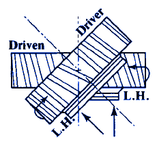
Helix gearing is a type of gearing that uses helical teeth to transmit motion between two shafts. The helical teeth are angled at a certain helix angle, which allows for smoother and more efficient transmission of motion. Helix gearing is commonly used in applications where high torque and efficiency are required. The design of helix gearing involves the calculation of various parameters, including the pitch diameter, helix angle, and tooth width.
Approximate Design Equations
The design of helical gears with shafts at any angle requires the use of approximate design equations. These equations are used to calculate the various parameters involved in the design of the gears, including the center distance, helix angle, and tooth width. The approximate design equations are based on the shrinkage and expansion of the gears, as well as the pitch line velocity and tooth load.
| Parameter | Equation |
|---|---|
| Center Distance | d = (N1 + N2) / (2 tan(α)) |
| Helix Angle | α = arctan(N2 / N1) |
| Tooth Width | b = (N1 π) / (2 tan(α)) |
Calculator for Helix Gearing
A calculator for helix gearing can be used to simplify the design process and reduce the error and uncertainty involved in the calculations. The calculator can be used to calculate the various parameters involved in the design of the gears, including the center distance, helix angle, and tooth width. The calculator can also be used to perform sensitivity analysis and optimization of the design.
Mathematical Models for Helix Gearing
The design of helical gears with shafts at any angle requires the use of mathematical models to simulate the behavior of the gears. The mathematical models can be used to calculate the stress and strain on the gears, as well as the efficiency and torque of the system. The mathematical models can also be used to perform parametric analysis and optimization of the design.
Applications of Helix Gearing
Helix gearing with shafts at any angle has a wide range of applications in various fields, including robotics, machine tools, and other mechanical systems. The use of helix gearing in these applications provides several advantages, including high torque and efficiency, smooth transmission of motion, and low vibration and noise. The design of helix gearing requires a deep understanding of the geometry and kinematics of the gears, as well as the mathematical models and calculations involved in their design.
How to calculate center distance between helical gears?
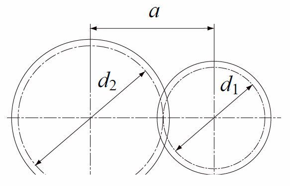
To calculate the center distance between helical gears, you need to consider the pitch circle diameter and the helix angle of the gears. The center distance is the distance between the centers of the two gears, and it can be calculated using the following formula: Center Distance = (Pitch Circle Diameter of Gear 1 + Pitch Circle Diameter of Gear 2) / 2. This formula takes into account the diametral pitch and the number of teeth of each gear.
Understanding Helical Gear Geometry
The geometry of helical gears is more complex than that of spur gears, due to the helix angle. The helix angle is the angle between the tooth profile and the pitch circle, and it can range from a few degrees to over 30 degrees. To calculate the center distance, you need to understand the helical gear geometry, including the pitch circle diameter, helix angle, and tooth profile.
- Pitch circle diameter: the diameter of the circle that passes through the centers of the teeth.
- Helix angle: the angle between the tooth profile and the pitch circle.
- Tooth profile: the shape of the teeth, including the tooth thickness and space width.
Calculating Pitch Circle Diameter
The pitch circle diameter is a critical parameter in calculating the center distance. It can be calculated using the following formula: Pitch Circle Diameter = (Number of Teeth x Diametral Pitch) / (π x helix angle). This formula takes into account the number of teeth, diametral pitch, and helix angle of the gear.
- Diametral pitch: the number of teeth per unit diameter.
- Number of teeth: the total number of teeth on the gear.
- Helix angle: the angle between the tooth profile and the pitch circle.
Determining Center Distance
The center distance can be calculated using the formula mentioned earlier: Center Distance = (Pitch Circle Diameter of Gear 1 + Pitch Circle Diameter of Gear 2) / 2. This formula assumes that the pitch circle diameters of the two gears are known, and that the helix angle is the same for both gears.
- Pitch circle diameter of gear 1: the pitch circle diameter of the first gear.
- Pitch circle diameter of gear 2: the pitch circle diameter of the second gear.
- Helix angle: the angle between the tooth profile and the pitch circle.
Accounting for Helix Angle
The helix angle plays a significant role in calculating the center distance. A larger helix angle results in a larger center distance, while a smaller helix angle results in a smaller center distance. To account for the helix angle, you need to use the helix angle factor, which is a correction factor that takes into account the helix angle.
- Helix angle factor: a correction factor that takes into account the helix angle.
- Center distance: the distance between the centers of the two gears.
- Helix angle: the angle between the tooth profile and the pitch circle.
Considering Gear Design Parameters
When calculating the center distance, you need to consider various gear design parameters, including the number of teeth, diametral pitch, and helix angle. These parameters can affect the center distance and the gear performance.
- Number of teeth: the total number of teeth on the gear.
- Diametral pitch: the number of teeth per unit diameter.
- Helix angle: the angle between the tooth profile and the pitch circle.
What is the formula for the helical gear angle?

The formula for the helical gear angle is a complex mathematical equation that involves several variables, including the pitch circle diameter, number of teeth, and helix angle. The formula is: tan(θ) = (z2 - z1) / (2 π (d2 - d1) tan(β)), where θ is the helical gear angle, z1 and z2 are the number of teeth on the two gears, d1 and d2 are the pitch circle diameters, and β is the helix angle.
The foundations of helical gears are based on the principles of gear geometry and kinematics. To understand the formula for the helical gear angle, it is essential to grasp the concepts of pitch circle diameter, number of teeth, and helix angle. Some key points to consider are:
- The pitch circle diameter is the diameter of the circle that passes through the center of each tooth on the gear.
- The number of teeth on each gear determines the gear ratio and the torque transmitted between the gears.
- The helix angle is the angle between the teeth and the axis of rotation of the gear.
Calculating the helical gear angle involves using the formula: tan(θ) = (z2 - z1) / (2 π (d2 - d1) tan(β)). This formula requires knowledge of the number of teeth, pitch circle diameters, and helix angle. Some key considerations are:
- The number of teeth on each gear must be known to determine the gear ratio and the torque transmitted between the gears.
- The pitch circle diameters of the two gears must be known to determine the distance between the gears.
- The helix angle must be known to determine the angle at which the teeth intersect.
Applications of helical gears are diverse and include transmissions, pumps, and generators. The helical gear angle is critical in these applications as it determines the efficiency and reliability of the system. Some key points to consider are:
- Helical gears are used in transmissions to provide smooth and quiet operation.
- Helical gears are used in pumps to provide high-pressure and high-flow rates.
- Helical gears are used in generators to provide high-efficiency and reliability.
Designing helical gears requires careful consideration of the helical gear angle, number of teeth, and pitch circle diameters. The design process involves using computer-aided design software and finite element analysis to optimize the gear design. Some key considerations are:
- The helical gear angle must be optimized to provide the desired gear ratio and torque transmission.
- The number of teeth must be optimized to provide the desired gear ratio and smooth operation.
- The pitch circle diameters must be optimized to provide the desired distance between the gears and smooth operation.
Manufacturing helical gears involves using machining and grinding techniques to produce high-precision gears. The manufacturing process requires careful consideration of the helical gear angle, number of teeth, and pitch circle diameters. Some key points to consider are:
- The helical gear angle must be accurately machined to provide the desired gear ratio and torque transmission.
- The number of teeth must be accurately machined to provide the desired gear ratio and smooth operation.
- The pitch circle diameters must be accurately ground to provide the desired distance between the gears and smooth operation.
How to calculate helical gear OD?

To calculate the helical gear OD, you need to consider the pitch diameter, addendum, and dedendum of the gear. The helical gear OD is typically calculated using the formula: OD = Pitch Diameter + 2 Addendum. However, this formula assumes a standard addendum and dedendum. In practice, the helical gear OD may vary depending on the specific gear design and manufacturing process.
Understanding Helical Gear Terminology
To accurately calculate the helical gear OD, it's essential to understand the terminology used in gear design. Key terms include pitch diameter, addendum, dedendum, and helix angle. The pitch diameter is the diameter of the gear at the pitch circle, which is the circle that passes through the teeth of the gear. The addendum is the distance from the pitch circle to the outside diameter of the gear, while the dedendum is the distance from the pitch circle to the root diameter of the gear. Some important considerations include:
- The helix angle affects the gear's tooth thickness and overlap, which can impact the helical gear OD.
- The pitch diameter and addendum are critical in determining the helical gear OD.
- The dedendum is essential in ensuring the gear's structural integrity and durability.
Calculating Helical Gear OD Using Formulas
The helical gear OD can be calculated using various formulas, depending on the gear design and manufacturing process. One common formula is: OD = Pitch Diameter + 2 Addendum. However, this formula assumes a standard addendum and dedendum. In practice, the helical gear OD may vary depending on the specific gear design and manufacturing process. Some key formulas include:
- OD = Pitch Diameter + 2 Addendum (for standard addendum and dedendum).
- OD = Pitch Diameter + 2 (Addendum + gear tooth thickness / 2) (for non-standard addendum and dedendum).
- OD = pitch circle diameter + 2 addendum + gear tooth thickness (for complex gear designs).
Accounting for Helix Angle and Tooth Thickness
The helix angle and tooth thickness can significantly impact the helical gear OD. A larger helix angle can result in a larger helical gear OD, while a smaller tooth thickness can result in a smaller helical gear OD. To accurately calculate the helical gear OD, it's essential to account for the helix angle and tooth thickness. Some important considerations include:
- The helix angle affects the gear's tooth thickness and overlap, which can impact the helical gear OD.
- A larger helix angle can result in a larger helical gear OD.
- A smaller tooth thickness can result in a smaller helical gear OD.
Factors Affecting Helical Gear OD
Several factors can affect the helical gear OD, including the gear material, manufacturing process, and design tolerances. The gear material can impact the gear's strength and durability, which can affect the helical gear OD. The manufacturing process can also impact the helical gear OD, as different manufacturing methods can result in varying levels of accuracy and precision. Some key factors include:
- The gear material affects the gear's strength and durability, which can impact the helical gear OD.
- The manufacturing process can impact the helical gear OD, as different manufacturing methods can result in varying levels of accuracy and precision.
- Design tolerances can also affect the helical gear OD, as they can impact the gear's fit and functionality.
Verifying Helical Gear OD Using Software orCalculations
To verify the helical gear OD, you can use software or perform calculations. Software can quickly and accurately calculate the helical gear OD, taking into account various design parameters and manufacturing constraints. Alternatively, you can perform manual calculations using formulas and tables. Some important considerations include:
- Using software can quickly and accurately calculate the helical gear OD.
- Performing manual calculations can provide a more detailed understanding of the gear design and manufacturing process.
- Verifying the helical gear OD is essential to ensure the gear's fit and functionality.
What is the best helix angle for helical gears?
The best helix angle for helical gears is a critical factor in determining their performance and efficiency. The helix angle is the angle between the tooth profile and the axis of rotation. A proper helix angle ensures smooth engagement, reduced noise, and increased load-carrying capacity. The ideal helix angle depends on the specific application, gear ratio, and operating conditions.
Helix Angle and Gear Efficiency
The helix angle has a significant impact on the efficiency of helical gears. A higher helix angle can lead to reduced efficiency due to increased friction and heat generation. However, a lower helix angle can result in poor tooth engagement and increased noise. The optimal helix angle for maximum efficiency is typically between 15° and 30°. Some key factors to consider when selecting a helix angle for efficient gear operation include:
- Gear ratio: A higher gear ratio requires a lower helix angle to maintain smooth engagement.
- Operating speed: Higher operating speeds require a higher helix angle to reduce friction and heat generation.
- Load capacity: Higher load capacities require a lower helix angle to increase tooth strength and durability.
Helix Angle and Tooth Strength
The helix angle also affects the tooth strength of helical gears. A lower helix angle can lead to increased tooth strength due to the reduced bending stress. However, a higher helix angle can result in reduced tooth strength due to the increased bending stress. The optimal helix angle for maximum tooth strength is typically between 10° and 25°. Some key factors to consider when selecting a helix angle for tooth strength include:
- Material properties: The material properties of the gear teeth, such as yield strength and toughness, affect the optimal helix angle for tooth strength.
- Tooth profile: The tooth profile, including the tooth width and tooth height, affects the optimal helix angle for tooth strength.
- Load capacity: The load capacity of the gear affects the optimal helix angle for tooth strength, with higher loads requiring lower helix angles.
Helix Angle and Noise Reduction
The helix angle can also impact the noise level of helical gears. A higher helix angle can lead to reduced noise due to the smoother engagement of the teeth. However, a lower helix angle can result in increased noise due to the poorer engagement of the teeth. The optimal helix angle for minimum noise is typically between 20° and 35°. Some key factors to consider when selecting a helix angle for noise reduction include:
- Tooth profile: The tooth profile, including the tooth width and tooth height, affects the optimal helix angle for noise reduction.
- Operating speed: Higher operating speeds require a higher helix angle to reduce noise and vibration.
- Load capacity: The load capacity of the gear affects the optimal helix angle for noise reduction, with higher loads requiring lower helix angles.
Helix Angle and Manufacturing Considerations
The helix angle can also impact the manufacturing process of helical gears. A higher helix angle can lead to increased manufacturing complexity due to the more complex tooth profile. However, a lower helix angle can result in reduced manufacturing complexity due to the simpler tooth profile. The optimal helix angle for manufacturing considerations is typically between 15° and 30°. Some key factors to consider when selecting a helix angle for manufacturing include:
- Machine capabilities: The machine capabilities, including the accuracy and precision, affect the optimal helix angle for manufacturing.
- Tooling costs: The tooling costs, including the cost of cutting tools and grinding wheels, affect the optimal helix angle for manufacturing.
- Production volume: The production volume affects the optimal helix angle for manufacturing, with higher volumes requiring more efficient manufacturing processes.
Helix Angle and Application-Specific Considerations
The helix angle can also be affected by application-specific considerations, such as the type of gear, operating conditions, and performance requirements. For! example, aerospace gears may require a higher helix angle to reduce noise and vibration, while industrial gears may require a lower helix angle to increase tooth strength and durability. Some key factors to consider when selecting a helix angle for application-specific considerations include:
- Gear type: The type of gear, including spur gears, helical gears, and bevel gears, affects the optimal helix angle for the application.
- Operating conditions: The operating conditions, including temperature, humidity, and vibration, affect the optimal helix angle for the application.
- Performance requirements: The performance requirements, including speed, torque, and efficiency, affect the optimal helix angle for the application.
Frequently Asked Questions (FAQs)
What is Helix Gearing with Shafts at Any Angle Center Distance and its Importance in Mechanical Engineering?
Helix gearing with shafts at any angle center distance is a type of gearing system that allows for the transmission of rotational motion between two shafts that are not parallel to each other. This type of gearing system is commonly used in mechanical engineering applications where the shafts are at an angle to each other, such as in robotics, aerospace engineering, and automotive engineering. The importance of helix gearing with shafts at any angle center distance lies in its ability to provide a smooth and efficient transmission of power between the two shafts, while also allowing for a flexible and compact design. The use of helical gears in this type of gearing system provides a number of advantages, including reduced vibration, increased torque capacity, and improved efficiency.
How do Approximate Design Equations and Calculators Help in the Design of Helix Gearing with Shafts at Any Angle Center Distance?
Approximate design equations and calculators play a crucial role in the design of helix gearing with shafts at any angle center distance. These tools allow engineers to quickly and accurately calculate the gear ratios, tooth numbers, and center distances required for a given application. The use of approximate design equations and calculators helps to streamline the design process, reducing the time and effort required to design and optimize a helix gearing system. Additionally, these tools help to minimize the risk of errors and miscalculations, ensuring that the final design meets the required performance and efficiency standards. By using approximate design equations and calculators, engineers can also explore different design options and optimize the gearing system for specific applications.
What are the Key Factors to Consider When Designing Helix Gearing with Shafts at Any Angle Center Distance?
When designing helix gearing with shafts at any angle center distance, there are several key factors to consider. One of the most important factors is the center distance between the two shafts, which must be carefully calculated to ensure that the gearing system operates smoothly and efficiently. Another important factor is the gear ratio, which must be selected to provide the required torque and speed for the application. The tooth numbers and helix angle of the gears must also be carefully chosen to ensure that the gearing system operates quietly and vibration-free. Additionally, the materials and manufacturing processes used to produce the gears must be selected to ensure that the gearing system meets the required performance and durability standards. By carefully considering these key factors, engineers can design a helix gearing system that meets the required performance and efficiency standards.
How can Helix Gearing with Shafts at Any Angle Center Distance be Optimized for Specific Applications?
Helix gearing with shafts at any angle center distance can be optimized for specific applications by using a combination of advanced design techniques and specialized software tools. One way to optimize the gearing system is to use finite element analysis to simulate the behavior of the gears under different loads and operating conditions. This allows engineers to identify potential weaknesses and optimize the design to minimize stress and vibration. Another way to optimize the gearing system is to use genetic algorithms or other optimization techniques to search for the optimal gear ratios, tooth numbers, and helix angles for a given application. By using these advanced design techniques and specialized software tools, engineers can optimize the helix gearing system to provide maximum performance, efficiency, and reliability for a wide range of applications.
Deja una respuesta
Entradas Relacionadas