
Fixed Fastener Condition and Projection Zone Tolerance Calculator

The Fixed Fastener Condition and Projection Zone Tolerance Calculator is a specialized tool designed to simplify the process of determining the optimal tolerances for fasteners in various engineering applications. This calculator takes into account the fixed fastener condition, projection zone, and other critical factors to provide accurate calculations. By utilizing this calculator, engineers can ensure that their designs meet the required standards, reducing the risk of errors and improving overall efficiency. The calculator's user-friendly interface and advanced algorithms make it an essential tool for professionals in the field of mechanical engineering and design. Its applications are vast.
- Understanding the Fixed Fastener Condition and Projection Zone Tolerance Calculator
- What is the formula for fixed fastener tolerance?
-
What is the formula for projected tolerance zone?
- Understanding the Projected Tolerance Zone Formula
- Key Factors in Calculating the Projected Tolerance Zone
- Types of Geometric Tolerance and Their Effect on the Projected Tolerance Zone
- Applications of the Projected Tolerance Zone Formula
- Limitations and Challenges of the Projected Tolerance Zone Formula
- What is the formula for calculating position tolerance?
- When to use projected tolerance?
-
Frequently Asked Questions (FAQs)
- What is the purpose of the Fixed Fastener Condition and Projection Zone Tolerance Calculator?
- How does the Fixed Fastener Condition and Projection Zone Tolerance Calculator work?
- What are the benefits of using the Fixed Fastener Condition and Projection Zone Tolerance Calculator?
- What types of applications can the Fixed Fastener Condition and Projection Zone Tolerance Calculator be used for?
Understanding the Fixed Fastener Condition and Projection Zone Tolerance Calculator
The Fixed Fastener Condition and Projection Zone Tolerance Calculator is a tool used to determine the tolerance of fasteners in a specific projection zone. This calculator is essential in various engineering fields, including aerospace, automotive, and industrial applications. It helps engineers and designers to ensure that the fasteners used in their projects meet the required standards and specifications.
Introduction to Fixed Fastener Condition
The Fixed Fastener Condition refers to the state of a fastener when it is securely attached to a surface or component. This condition is crucial in determining the structural integrity of a system or assembly. The Fixed Fastener Condition and Projection Zone Tolerance Calculator takes into account various factors, including the type of fastener, material, and surface finish, to calculate the tolerance of the fastener in the projection zone.
Understanding Projection Zone Tolerance
The Projection Zone Tolerance refers to the allowable deviation of a fastener from its nominal position in a specific projection zone. This tolerance is critical in ensuring that the fastener is properly aligned and secured to prevent errors or failures in the system or assembly. The Fixed Fastener Condition and Projection Zone Tolerance Calculator uses complex algorithms and mathematical models to calculate the tolerance of the fastener in the projection zone.
Key Factors Affecting Tolerance Calculation
Several factors affect the tolerance calculation of the Fixed Fastener Condition and Projection Zone Tolerance Calculator. These include:
| Factor | Description |
|---|---|
| Fastener Type | The type of fastener used, such as screw, bolt, or nut. |
| Material | The material of the fastener and the surface it is attached to. |
| Surface Finish | The surface finish of the fastener and the surface it is attached to. |
Applications of the Calculator
The Fixed Fastener Condition and Projection Zone Tolerance Calculator has various applications in engineering fields, including:
| Application | Description |
|---|---|
| Aerospace | Ensuring the structural integrity of aircraft and spacecraft components. |
| Automotive | Ensuring the safety and reliability of vehicle components. |
| Industrial | Ensuring the efficiency and productivity of industrial equipment. |
Benefits of Using the Calculator
The Fixed Fastener Condition and Projection Zone Tolerance Calculator offers several benefits, including:
| Benefit | Description |
|---|---|
| Improved Accuracy | Ensuring that fasteners are properly aligned and secured. |
| Reduced Errors | Minimizing errors and failures in systems and assemblies. |
| Increased Efficiency | Streamlining design and manufacturing processes. |
What is the formula for fixed fastener tolerance?

The formula for fixed fastener tolerance is determined by the International Organization for Standardization (ISO) and the American Society of Mechanical Engineers (ASME). The formula takes into account the nominal size of the fastener, the tolerance class, and the material of the fastener. The general formula is: tolerance = (nominal size x tolerance class x material factor). This formula is used to calculate the maximum and minimum allowable dimensions for a fastener.
Understanding Fastener Tolerance Classes
Fastener tolerance classes are defined by the ISO and ASME standards. These classes determine the tightness of the tolerance of the fastener. The most common tolerance classes are 2B, 3B, and 4B, with 2B being the loosest and 4B being the tightest. The tolerance class is used in the formula to calculate the allowable variation in the fastener's dimensions.
- The 2B tolerance class is used for general-purpose fasteners.
- The 3B tolerance class is used for precision fasteners.
- The 4B tolerance class is used for high-precision fasteners.
Calculating Fastener Tolerance
To calculate the fastener tolerance, you need to know the nominal size of the fastener, the tolerance class, and the material of the fastener. You can then use the formula to calculate the maximum and minimum allowable dimensions for the fastener. For example, if you have a 1-inch fastener with a 2B tolerance class, the maximum allowable dimension would be 1.01 inches and the minimum allowable dimension would be 0.99 inches.
- Determine the nominal size of the fastener.
- Select the tolerance class based on the application.
- Calculate the maximum and minimum allowable dimensions using the formula.
Importance of Fastener Tolerance
Fastener tolerance is critical in ensuring the proper fit and function of a fastener. If the tolerance is too loose, the fastener may not fit properly, leading to assembly issues. If the tolerance is too tight, the fastener may be difficult to assemble, leading to increased costs and reduced productivity.
- Proper fit is essential for ensuring the fastener functions as intended.
- Assembly issues can be avoided by selecting the correct tolerance class.
- Increased costs can result from tight tolerances that require specialized tooling and equipment.
Factors Affecting Fastener Tolerance
Several factors can affect the fastener tolerance, including the material of the fastener, the manufacturing process, and the application. For example, fasteners made from plastics may have a looser tolerance than those made from metals.
- The material of the fastener can affect the tolerance due to variations in dimensional stability.
- The manufacturing process can affect the tolerance due to variations in machining and assembly.
- The application can affect the tolerance due to variations in operating conditions and environmental factors.
Standards for Fastener Tolerance
The ISO and ASME standards provide guidelines for fastener tolerance. These standards define the tolerance classes, material factors, and calculation methods for determining the fastener tolerance. By following these standards, manufacturers can ensure that their fasteners meet the required specifications and industry standards.
- The ISO 286-1 standard defines the tolerance classes for fasteners.
- The ASME B18.2.2 standard defines the material factors for fasteners.
- The ISO 1101 standard defines the calculation methods for determining the fastener tolerance.
What is the formula for projected tolerance zone?
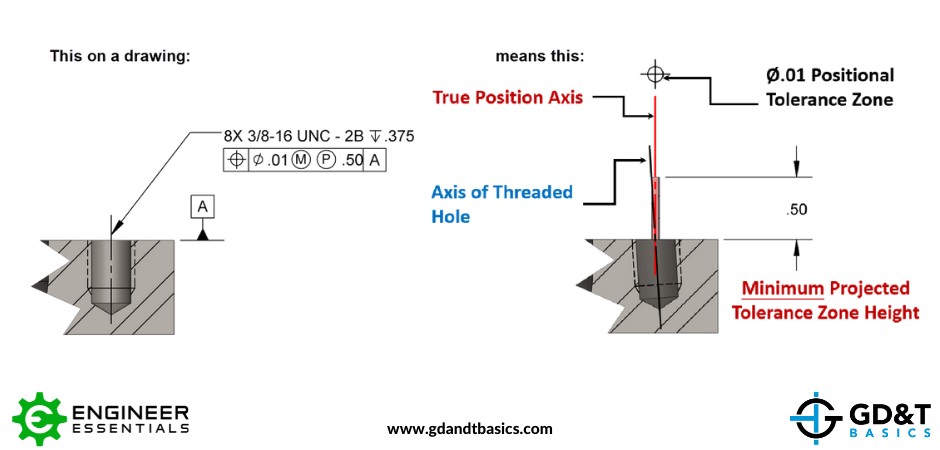
The formula for the projected tolerance zone is a mathematical representation of the geometric tolerance that is used to specify the permissible variation in the position and orientation of a feature or a set of features on a part or assembly. The formula is based on the ASME Y14.5 standard and takes into account the size, shape, and orientation of the feature, as well as the datum references and the tolerance values specified in the design.
Understanding the Projected Tolerance Zone Formula
The projected tolerance zone formula is used to calculate the maximum and minimum limits of the tolerance zone, which is the three-dimensional space within which the feature or set of features must lie. The formula involves the use of geometric parameters such as the radius, diameter, and angle, as well as tolerance values such as the plus and minus tolerances. The formula is:
- The projected tolerance zone is calculated as the perpendicular distance from the datum reference to the feature or set of features.
- The projected tolerance zone is based on the size and shape of the feature, as well as the orientation and position of the feature.
- The projected tolerance zone is used to control the permissible variation in the position and orientation of the feature or set of features.
Key Factors in Calculating the Projected Tolerance Zone
The calculation of the projected tolerance zone involves several key factors, including the size and shape of the feature, the orientation and position of the feature, and the datum references and tolerance values specified in the design. The projected tolerance zone is also affected by the type of geometric tolerance specified, such as position, orientation, or profile. The factors are:
- The size and shape of the feature, which affect the size and shape of the projected tolerance zone.
- The orientation and position of the feature, which affect the location and orientation of the projected tolerance zone.
- The datum references and tolerance values specified in the design, which affect the size and location of the projected tolerance zone.
Types of Geometric Tolerance and Their Effect on the Projected Tolerance Zone
There are several types of geometric tolerance, including position, orientation, and profile, each of which affects the projected tolerance zone in a different way. The type of geometric tolerance specified in the design determines the size and shape of the projected tolerance zone, as well as its location and orientation. The types are:
- Position tolerance, which controls the permissible variation in the position of the feature or set of features.
- Orientation tolerance, which controls the permissible variation in the orientation of the feature or set of features.
- Profile tolerance, which controls the permissible variation in the profile or shape of the feature or set of features.
Applications of the Projected Tolerance Zone Formula
The projected tolerance zone formula has several practical applications in the field of engineering and manufacturing, including the design and manufacture of parts and assemblies, and the inspection and testing of parts and assemblies. The formula is used to ensure that parts and assemblies are manufactured and assembled within the permissible limits of tolerance, and to verify that they meet the required specifications. The applications are:
- The design and manufacture of parts and assemblies, where the projected tolerance zone formula is used to ensure that the parts and assemblies are manufactured and assembled within the permissible limits of tolerance.
- The inspection and testing of parts and assemblies, where the projected tolerance zone formula is used to verify that the parts and assemblies meet the required specifications.
- The quality control of parts and assemblies, where the projected tolerance zone formula is used to ensure that the parts and assemblies are manufactured and assembled within the permissible limits of tolerance.
Limitations and Challenges of the Projected Tolerance Zone Formula
The projected tolerance zone formula has several limitations and challenges, including the complexity of the mathematical calculations involved, and the difficulty of interpreting and applying the results. The formula is also sensitive to errors and uncertainties in the input data, and requires specialized expertise and software to apply and interpret correctly. The limitations and challenges are:
- The complexity of the mathematical calculations involved, which can make it difficult to apply and interpret the formula correctly.
- The difficulty of interpreting and applying the results, which requires specialized expertise and software.
- The sensitivity of the formula to errors and uncertainties in the input data, which can affect the accuracy and reliability of the results.
What is the formula for calculating position tolerance?
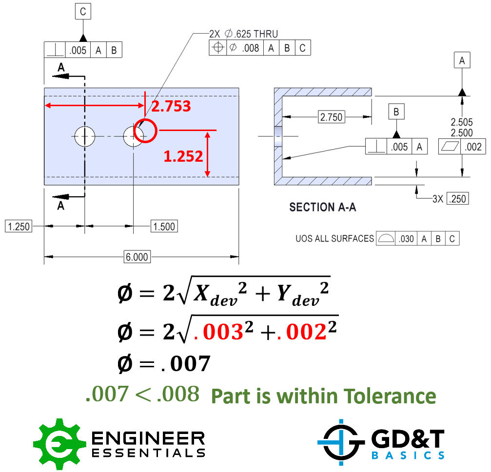
The formula for calculating position tolerance is a complex concept that involves several variables, including the acceptance criteria, measurement uncertainty, and specs. The position tolerance is the maximum allowed deviation from the nominal position of a part or feature. The formula for calculating position tolerance is: Position Tolerance = (Actual Measurement - Nominal Position) / Measurement Uncertainty.
Understanding Position Tolerance
Position tolerance is a critical concept in engineering and manufacturing, as it determines the allowable variation in the position of a part or feature. To calculate position tolerance, one must first understand the nominal position, which is the ideal or desired position of the part or feature. Then, one must measure the actual position of the part or feature and calculate the deviation from the nominal position. The position tolerance can be calculated using the following steps:
- The actual measurement of the part or feature is taken using a measurement instrument.
- The nominal position of the part or feature is determined from the design specifications.
- The measurement uncertainty is determined based on the instrument accuracy and operators' skills.
Types of Position Tolerance
There are several types of position tolerance, including unilateral tolerance, bilateral tolerance, and symmetrical tolerance. The type of position tolerance used depends on the application and the requirements of the part or feature. For example, unilateral tolerance is used when the part or feature can only deviate in one direction, while bilateral tolerance is used when the part or feature can deviate in both directions. The main differences between these types of position tolerance are:
- Unilateral tolerance allows deviation in only one direction.
- Bilateral tolerance allows deviation in both directions.
- Symmetrical tolerance is a type of bilateral tolerance that allows equal deviation in both directions.
Factors Affecting Position Tolerance
Several factors can affect the position tolerance, including material properties, manufacturing process, and measurement uncertainty. The material properties, such as thermal expansion and contraction, can affect the position of the part or feature. The manufacturing process, such as machining and assembly, can also introduce variations in the position of the part or feature. The main factors that affect position tolerance are:
- Material properties, such as thermal expansion and contraction.
- Manufacturing process, such as machining and assembly.
- Measurement uncertainty, which depends on the instrument accuracy and operators' skills.
Calculating Position Tolerance
To calculate position tolerance, one must first determine the actual measurement of the part or feature, then calculate the deviation from the nominal position. The position tolerance can be calculated using the formula: Position Tolerance = (Actual Measurement - Nominal Position) / Measurement Uncertainty. The steps to calculate position tolerance are:
- Determine the actual measurement of the part or feature using a measurement instrument.
- Calculate the deviation from the nominal position.
- Determine the measurement uncertainty based on the instrument accuracy and operators' skills.
Applications of Position Tolerance
Position tolerance has several applications in engineering and manufacturing, including quality control, inspection, and design. The position tolerance is used to ensure that the part or feature meets the specs and requirements. The main applications of position tolerance are:
- Quality control, to ensure that the part or feature meets the specs and requirements.
- Inspection, to verify that the part or feature is within the allowable variation.
- Design, to determine the nominal position and tolerance of the part or feature.
When to use projected tolerance?
When to use projected tolerance is a critical consideration in various fields, including engineering, manufacturing, and quality control. Projected tolerance refers to the maximum allowable deviation from a specified dimension or characteristic, considering the geometric and dimensional variations that may occur during the production process. It is essential to use projected tolerance when the assembly or interchangeability of parts is crucial, and any deviation may affect the performance or safety of the final product.
Understanding Projected Tolerance in Design
Projected tolerance is used during the design phase to ensure that the parts or components will assemble correctly and function as intended. The designer must consider the manufacturing process, materials, and tolerance requirements to specify the projected tolerance. This involves analyzing the geometric and dimensional variations that may occur during production, such as bending, twisting, or warping. The designer can use various tools, including computer-aided design (CAD) software, to simulate the production process and determine the projected tolerance.
- Tolerance analysis: The designer performs a tolerance analysis to determine the maximum allowable deviation from the specified dimensions.
- Geometric dimensioning: The designer uses geometric dimensioning to specify the tolerance requirements, considering the shape, size, and orientation of the parts.
- Manufacturing process planning: The designer plans the manufacturing process, considering the machining, assembly, and inspection requirements.
Applying Projected Tolerance in Manufacturing
Projected tolerance is applied during the manufacturing process to ensure that the parts or components meet the specified requirements. The manufacturer must consider the process capabilities, material properties, and equipment limitations to determine the projected tolerance. This involves monitoring the production process, inspecting the parts, and adjusting the manufacturing process as needed. The manufacturer can use various tools, including statistical process control (SPC), to monitor the production process and ensure that the projected tolerance is met.
- Process capability analysis: The manufacturer performs a process capability analysis to determine the capability of the manufacturing process.
- Tolerance allocation: The manufacturer allocates the tolerance requirements to the various stages of the manufacturing process.
- Inspection and testing: The manufacturer inspects and tests the parts to ensure that they meet the specified requirements.
Using Projected Tolerance in Quality Control
Projected tolerance is used in quality control to ensure that the final product meets the specified requirements. The quality control team must consider the inspection and testing requirements, as well as the sampling and acceptance criteria, to determine the projected tolerance. This involves monitoring the production process, inspecting the parts, and testing the final product to ensure that it meets the specified requirements.
- Inspection planning: The quality control team plans the inspection process, considering the sampling and acceptance criteria.
- Testing and validation: The quality control team tests and validates the final product to ensure that it meets the specified requirements.
- Corrective action: The quality control team takes corrective action if the final product does not meet the specified requirements.
Projected Tolerance in Assembly and Interchangeability
Projected tolerance is critical in assembly and interchangeability applications, where the fit and function of the parts are crucial. The designer must consider the geometric and dimensional variations that may occur during production, as well as the assembly and disassembly requirements, to specify the projected tolerance. This involves analyzing the clearance, interference, and alignment requirements to ensure that the parts assemble correctly and function as intended.
- Assembly analysis: The designer performs an assembly analysis to determine the clearance, interference, and alignment requirements.
- Tolerance allocation: The designer allocates the tolerance requirements to the various stages of the assembly process.
- Interchangeability analysis: The designer performs an interchangeability analysis to ensure that the parts are interchangeable.
Benefits of Using Projected Tolerance
Using projected tolerance provides several benefits, including improved quality, reduced costs, and increased efficiency. By considering the geometric and dimensional variations that may occur during production, the designer can specify the projected tolerance to ensure that the parts or components meet the specified requirements. This involves using various tools, including computer-aided design (CAD) software, to simulate the production process and determine the projected tolerance.
- Improved quality: Using projected tolerance ensures that the final product meets the specified requirements.
- Reduced costs: Using projected tolerance reduces the costs associated with rework, scrap, and warranty claims.
- Increased efficiency: Using projected tolerance increases the efficiency of the manufacturing process by reducing the inspection and testing requirements.
Frequently Asked Questions (FAQs)
What is the purpose of the Fixed Fastener Condition and Projection Zone Tolerance Calculator?
The Fixed Fastener Condition and Projection Zone Tolerance Calculator is a tool designed to help users determine the tolerance of a fastener in a specific application. This calculator takes into account the fixed fastener condition, which refers to the position and orientation of the fastener in relation to the surrounding components. By inputting the relevant parameters, such as the fastener size, material, and projected zone, the calculator can provide an accurate calculation of the tolerance required to ensure a proper fit and functionality of the fastener in the given application. The calculator is particularly useful in engineering and design applications where precise calculations are crucial to ensure the reliability and performance of the final product.
How does the Fixed Fastener Condition and Projection Zone Tolerance Calculator work?
The Fixed Fastener Condition and Projection Zone Tolerance Calculator works by using a complex algorithm that takes into account various input parameters to calculate the tolerance of the fastener. The user is required to input the fastener size, material, projected zone, and other relevant parameters into the calculator. The calculator then uses these inputs to perform a series of calculations based on geometric and mathematical formulas to determine the tolerance required. The calculator also considers the fixed fastener condition, which includes the position and orientation of the fastener, to ensure that the calculated tolerance is accurate and reliable. The result is a precise calculation of the tolerance required to ensure a proper fit and functionality of the fastener in the given application.
What are the benefits of using the Fixed Fastener Condition and Projection Zone Tolerance Calculator?
The Fixed Fastener Condition and Projection Zone Tolerance Calculator offers several benefits to users, particularly in engineering and design applications. One of the primary advantages is the ability to accurately calculate the tolerance required for a fastener in a specific application, ensuring a proper fit and functionality. This can help to reduce errors and improve the reliability of the final product. Additionally, the calculator can help users to save time and increase efficiency by providing a quick and accurate calculation of the tolerance required. The calculator is also easy to use and requires minimal input from the user, making it a valuable tool for anyone involved in design and engineering applications.
What types of applications can the Fixed Fastener Condition and Projection Zone Tolerance Calculator be used for?
The Fixed Fastener Condition and Projection Zone Tolerance Calculator can be used for a wide range of applications in various industries, including aerospace, automotive, construction, and manufacturing. The calculator is particularly useful in engineering and design applications where precise calculations are crucial to ensure the reliability and performance of the final product. Some examples of applications where the calculator can be used include aircraft and vehicle design, building construction, and machinery design. The calculator can also be used in research and development applications to test and optimize the design of new products and components. Overall, the Fixed Fastener Condition and Projection Zone Tolerance Calculator is a versatile tool that can be used in any application where the tolerance of a fastener needs to be accurately calculated.
Deja una respuesta
Entradas Relacionadas