
Fixed-Pinned Cantilever Beam Design Calculator
The Fixed-Pinned Cantilever Beam Design Calculator is a valuable tool for engineers and designers. It allows users to calculate the structural properties of a fixed-pinned cantilever beam, including deflection, stress, and reactions. By inputting parameters such as beam length, load, and material properties, users can quickly determine the beam's behavior under various conditions. This calculator is particularly useful for designing and optimizing cantilever beams in a wide range of applications, from building construction to mechanical engineering. It provides a fast and accurate way to analyze and design fixed-pinned cantilever beams.
-
Fixed-Pinned Cantilever Beam Design Calculator: A Comprehensive Tool for Structural Engineers
- Introduction to Fixed-Pinned Cantilever Beams
- Design Parameters for Fixed-Pinned Cantilever Beams
- Calculation Methods for Fixed-Pinned Cantilever Beams
- Advantages of Using the Fixed-Pinned Cantilever Beam Design Calculator
- Limitations and Assumptions of the Fixed-Pinned Cantilever Beam Design Calculator
- What is the formula for fixed cantilever?
- What is the rule of thumb for cantilever beam?
- What software is used to calculate SFD and BMD?
- How much weight can a cantilever beam hold calculator?
-
Frequently Asked Questions (FAQs)
- What is the purpose of the Fixed-Pinned Cantilever Beam Design Calculator?
- How does the Fixed-Pinned Cantilever Beam Design Calculator work?
- What are the advantages of using the Fixed-Pinned Cantilever Beam Design Calculator?
- What are the limitations of the Fixed-Pinned Cantilever Beam Design Calculator?
Fixed-Pinned Cantilever Beam Design Calculator: A Comprehensive Tool for Structural Engineers
The Fixed-Pinned Cantilever Beam Design Calculator is a powerful tool used by structural engineers to design and analyze cantilever beams with fixed and pinned ends. This calculator takes into account various factors such as the beam's length, material properties, and applied loads to determine the beam's stress, strain, and deflection. The calculator is essential in ensuring the structural integrity and safety of buildings, bridges, and other infrastructure.
Introduction to Fixed-Pinned Cantilever Beams
Fixed-pinned cantilever beams are a type of beam that is fixed at one end and pinned at the other. This type of beam is commonly used in structural engineering applications where a rigid connection is required at one end and a hinged connection is required at the other. The fixed end provides zero displacement and zero rotation, while the pinned end provides zero displacement but allows rotation.
Design Parameters for Fixed-Pinned Cantilever Beams
When designing a fixed-pinned cantilever beam, several parameters must be considered, including the beam's length, width, and height, as well as the material properties such as Young's modulus and Poisson's ratio. The applied loads, including point loads and distributed loads, must also be taken into account. The calculator uses these parameters to determine the beam's bending moment, shear force, and deflection.
Calculation Methods for Fixed-Pinned Cantilever Beams
The Fixed-Pinned Cantilever Beam Design Calculator uses various calculation methods to determine the beam's stress and deflection. These methods include the Bernoulli-Euler beam theory, which assumes that the beam is slender and straight, and the Timoshenko beam theory, which takes into account the beam's shear deformation and rotational inertia.
| Calculation Method | Description |
|---|---|
| Bernoulli-Euler Beam Theory | Assumes a slender and straight beam |
| Timoshenko Beam Theory | Takes into account shear deformation and rotational inertia |
Advantages of Using the Fixed-Pinned Cantilever Beam Design Calculator
The Fixed-Pinned Cantilever Beam Design Calculator offers several advantages, including fast and accurate calculations, easy to use interface, and comprehensive results. The calculator also allows users to iterate on their design and optimize their beam's performance.
Limitations and Assumptions of the Fixed-Pinned Cantilever Beam Design Calculator
The Fixed-Pinned Cantilever Beam Design Calculator is based on several assumptions and limitations, including the assumption of a linear elastic material behavior and the neglect of dynamical effects. The calculator also assumes that the beam is prismatic and straight, and that the applied loads are static. These limitations and assumptions must be taken into account when using the calculator to ensure accurate and reliable results. The calculator's results should be verified using experimental or numerical methods to ensure the structural integrity and safety of the beam.
What is the formula for fixed cantilever?
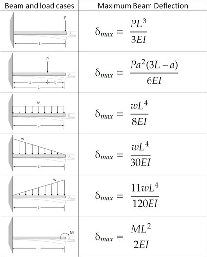
The formula for a fixed cantilever is a fundamental concept in structural analysis, which is used to determine the deflection and stress of a cantilever beam that is fixed at one end and free at the other. The formula is given by:
y = (W x^2) / (2 E I)
where y is the deflection of the beam, W is the load applied to the beam, x is the distance from the fixed end, E is the modulus of elasticity of the beam material, and I is the moment of inertia of the beam cross-section.
Understanding the Formula Components
The formula for a fixed cantilever involves several key components, including the load (W), distance (x), modulus of elasticity (E), and moment of inertia (I). To understand the formula, it is essential to grasp the concept of each component. The components can be broken down as follows:
- The load (W) is the force applied to the beam, which can be a point load or a distributed load.
- The distance (x) is the distance from the fixed end of the beam to the point where the load is applied.
- The modulus of elasticity (E) is a measure of the stiffness of the beam material, which determines how much the beam will deflect under a given load.
Calculating the Moment of Inertia
The moment of inertia (I) is a critical component in the formula for a fixed cantilever. It is a measure of the resistance of the beam to bending and is calculated based on the beam's cross-sectional shape and size. The moment of inertia can be calculated using the following formula:
- The area of the beam cross-section (A) is used to calculate the moment of inertia.
- The distance from the neutral axis (y) is used to calculate the moment of inertia.
- The thickness of the beam (t) is used to calculate the moment of inertia.
Applying the Formula to Real-World Scenarios
The formula for a fixed cantilever can be applied to a variety of real-world scenarios, including the design of buildings, bridges, and machinery. By using the formula, engineers can determine the maximum load that a cantilever beam can support without failing. The formula can be applied in the following ways:
- The formula can be used to determine the required size of the beam to support a given load.
- The formula can be used to determine the maximum load that a beam can support without failing.
- The formula can be used to optimize the design of a cantilever beam to minimize weight and cost.
Considering the Effects of External Factors
External factors, such as temperature and humidity, can affect the behavior of a fixed cantilever beam. These factors can cause the beam to expand or contract, which can lead to changes in the beam's deflection and stress. The effects of external factors can be considered in the following ways:
- The thermal expansion of the beam material can be calculated using the coefficient of thermal expansion.
- The moisture absorption of the beam material can be calculated using the moisture absorption coefficient.
- The effect of external factors on the beam's deflection and stress can be calculated using finite element analysis.
Validating the Formula through Experimental Testing
The formula for a fixed cantilever can be validated through experimental testing, which involves measuring the deflection and stress of a cantilever beam under various loads and conditions. The experimental results can be compared to the theoretical predictions made using the formula to validate its accuracy. The formula can be validated in the following ways:
- The deflection of the beam can be measured using displacement sensors.
- The stress of the beam can be measured using strain gauges.
- The experimental results can be compared to the theoretical predictions to validate the accuracy of the formula.
What is the rule of thumb for cantilever beam?
The rule of thumb for a cantilever beam is to ensure that the beam is designed to withstand the maximum load and stress at the fixed end, while also considering the deflection and stability of the beam. This is achieved by following certain guidelines and principles, such as ensuring that the beam is properly anchored and supported, and that the load is evenly distributed.
Design Considerations for Cantilever Beams
When designing a cantilever beam, there are several factors to consider, including the length and width of the beam, the material used, and the load that will be applied. The following are some key considerations:
- The beam should be designed to withstand the maximum load and stress at the fixed end.
- The beam should be properly anchored and supported to prevent deflection and instability.
- The load should be evenly distributed along the beam to prevent concentrated loads.
Load Calculation for Cantilever Beams
To calculate the load on a cantilever beam, it is necessary to consider the weight of the beam itself, as well as any external loads that will be applied. The following are some key steps:
- Determine the weight of the beam and any external loads.
- Calculate the maximum load that the beam will be subjected to.
- Use engineering formulas to calculate the stress and deflection of the beam.
Material Selection for Cantilever Beams
The material used for a cantilever beam is critical to its strength and stability. The following are some key factors to consider:
- The material should have a high tensile strength to withstand tension and compression.
- The material should have a high stiffness to resist deflection.
- The material should be durable and resistant to corrosion and fatigue.
Support and Anchoring for Cantilever Beams
Proper support and anchoring are essential for the stability and safety of a cantilever beam. The following are some key considerations:
- The beam should be properly anchored to prevent rotation and translation.
- The beam should be supported at the fixed end to prevent deflection and instability.
- The support system should be designed to withstand the maximum load and stress.
Failure Modes of Cantilever Beams
A cantilever beam can fail in several ways, including bending, tension, and compression. The following are some key failure modes:
- Bending failure occurs when the beam is subjected to a bending moment that exceeds its strength.
- Tension failure occurs when the beam is subjected to a tensile force that exceeds its strength.
- Compression failure occurs when the beam is subjected to a compressive force that exceeds its strength.
What software is used to calculate SFD and BMD?
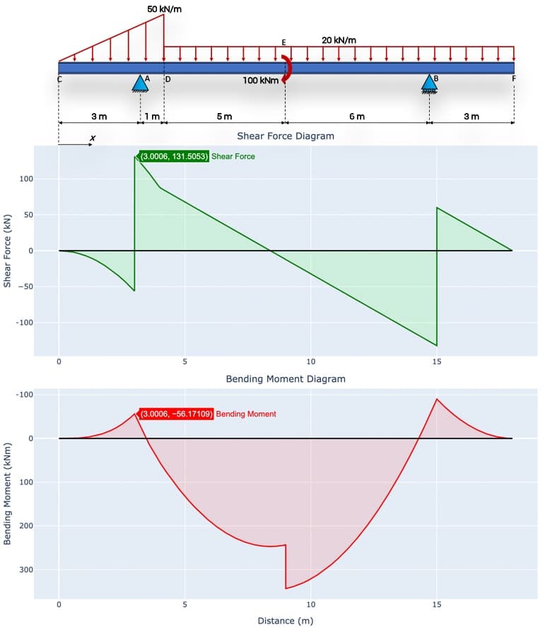
The software used to calculate Shear Force Diagram (SFD) and Bending Moment Diagram (BMD) is typically specialized engineering software that can handle complex calculations and visualize the results. Some of the most commonly used software for this purpose include SAP2000, ETABS, STAAD.Pro, and Autodesk Robot Structural Analysis. These software programs use finite element analysis and numerical methods to calculate the shear forces and bending moments in a structure, and then generate the corresponding diagrams.
Software Selection Criteria
When selecting software to calculate SFD and BMD, engineers consider factors such as the type of structure, the level of complexity, and the analysis capabilities. Here are some key considerations:
- The software should be able to handle static and dynamic analysis
- The software should have a user-friendly interface and be easy to use
- The software should be able to generate accurate and reliable results
The selected software should also be able to import and export data in various formats, and have good technical support.
Key Features of SFD and BMD Software
The software used to calculate SFD and BMD should have certain key features, including:
- Structural modeling capabilities to create accurate models of the structure
- Load application capabilities to apply various types of loads to the structure
- Analysis capabilities to perform static and dynamic analysis of the structure
The software should also be able to generate reports and diagrams that are easy to understand and interpret.
Applications of SFD and BMD Software
The software used to calculate SFD and BMD has a wide range of applications in civil engineering, mechanical engineering, and aerospace engineering. Some of the key applications include:
- Building design and analysis
- Bridge design and analysis
- Aircraft design and analysis
The software can also be used to analyze and design machinery, equipment, and other structures.
Benefits of Using SFD and BMD Software
The use of software to calculate SFD and BMD has several benefits, including:
- Increased accuracy and reliability of results
- Reduced time and effort required for analysis and design
- Improved safety and reduced risk of failure
The software can also help engineers to optimize designs and reduce costs.
Future Developments in SFD and BMD Software
The future of SFD and BMD software is likely to involve advances in technology and increased use of artificial intelligence and machine learning. Some of the key developments include:
- Cloud-based software and collaboration tools
- Integration with other software and tools
- Increased use of Building Information Modeling (BIM)
These developments will likely lead to increased efficiency and productivity in the engineering design and analysis process.
How much weight can a cantilever beam hold calculator?
To determine how much weight a cantilever beam can hold, a calculator or a structural analysis software is often used. These tools take into account various factors such as the beam's material, its length, width, and thickness, as well as the load type and location. The calculator uses formulas and algorithms to calculate the maximum weight that the beam can safely support without bending or breaking.
Understanding Cantilever Beam Mechanics
The mechanics of a cantilever beam are complex, and the calculator must consider factors such as tension, compression, and shear forces. The beam's geometry and material properties also play a crucial role in determining its load-carrying capacity. The calculator uses the following steps to calculate the weight:
- Calculate the moment of inertia of the beam to determine its resistance to bending.
- Determine the maximum stress that the beam can withstand without failing.
- Calculate the maximum weight that the beam can support based on the load type and location.
Factors Affecting Cantilever BeamCapacity
Several factors can affect the capacity of a cantilever beam, including the beam's material, size, and shape. The load type and location also play a significant role in determining the beam's load-carrying capacity. The calculator considers the following factors:
- Material properties, such as the modulus of elasticity and yield strength.
- Beam geometry, including the length, width, and thickness.
- Load type, including point loads, uniformly distributed loads, and moment loads.
Cantilever Beam Calculator Inputs
To use a cantilever beam calculator, the user must input various parameters, including the beam's material, size, and shape, as well as the load type and location. The calculator also requires information about the support conditions, such as the boundary conditions and restraints. The user must provide the following inputs:
- Beam material, including the density, modulus of elasticity, and yield strength.
- Beam geometry, including the length, width, and thickness.
- Load type and location, including the magnitude and direction of the load.
Cantilever Beam Calculator Outputs
The cantilever beam calculator provides various outputs, including the maximum weight that the beam can safely support, as well as the stress and deflection of the beam under the given load conditions. The calculator also provides information about the beam's stability and buckling behavior. The outputs include:
- Maximum weight that the beam can support without failing.
- Stress distribution along the beam, including the maximum stress and minimum stress.
- Deflection of the beam under the given load conditions.
Limitations of Cantilever Beam Calculators
While cantilever beam calculators are powerful tools, they have limitations and assumptions that must be considered. The calculator assumes a linear elastic behavior of the beam, which may not always be the case. The calculator also assumes a specific load type and location, which may not accurately represent the real-world conditions. The limitations include:
- Assumptions about the beam's material behavior, including the linear elastic assumption.
- Simplifications of the load conditions, including the load type and location.
- Neglect of non-linear effects, such as large deformations and contact forces.
Frequently Asked Questions (FAQs)
What is the purpose of the Fixed-Pinned Cantilever Beam Design Calculator?
The Fixed-Pinned Cantilever Beam Design Calculator is a tool used to calculate the stresses and deflections of a cantilever beam with a fixed end and a pinned end. This type of beam is commonly used in various engineering applications, such as building design, bridge construction, and mechanical engineering. The calculator takes into account the length of the beam, the load applied to it, and the material properties of the beam, such as its young's modulus and moment of inertia. By using this calculator, engineers can determine the maximum stress and deflection of the beam, which is essential for ensuring the structural integrity and safety of the design.
How does the Fixed-Pinned Cantilever Beam Design Calculator work?
The Fixed-Pinned Cantilever Beam Design Calculator works by using the beam theory equations to calculate the bending moment and shear force diagrams of the beam. The calculator first calculates the reaction forces at the fixed and pinned ends of the beam, and then uses these forces to calculate the bending moment and shear force at any point along the length of the beam. The calculator also takes into account the boundary conditions of the beam, such as the fixed end and pinned end, to ensure that the calculations are accurate and relevant to the specific design. The calculator then uses the material properties of the beam to calculate the stress and deflection of the beam, which can be used to determine the structural integrity and safety of the design.
What are the advantages of using the Fixed-Pinned Cantilever Beam Design Calculator?
The Fixed-Pinned Cantilever Beam Design Calculator has several advantages that make it a useful tool for engineers. One of the main advantages is that it allows engineers to quickly and easily calculate the stresses and deflections of a cantilever beam with a fixed end and a pinned end. This can save a significant amount of time and effort compared to manual calculations, which can be error-prone and time-consuming. Another advantage is that the calculator can handle a wide range of input parameters, including different load types, material properties, and boundary conditions. This makes it a versatile tool that can be used for a variety of engineering applications. Additionally, the calculator provides detailed and accurate results, which can be used to optimize the design of the beam and ensure that it meets the required safety and performance standards.
What are the limitations of the Fixed-Pinned Cantilever Beam Design Calculator?
The Fixed-Pinned Cantilever Beam Design Calculator has some limitations that need to be considered when using it. One of the main limitations is that it assumes a simple and linear behavior of the beam, which may not always be the case in real-world applications. The calculator also assumes that the material properties of the beam are constant and uniform, which may not be true for all materials. Additionally, the calculator does not take into account non-linear effects such as large deflections or plastic deformation, which can be important in certain engineering applications. Furthermore, the calculator is only applicable to cantilever beams with a fixed end and a pinned end, and may not be suitable for other types of beams or structures. Therefore, engineers need to carefully evaluate the assumptions and limitations of the calculator to ensure that it is used appropriately and that the results are valid and reliable.
Deja una respuesta
Entradas Relacionadas