
Stress Deflection Moment Equations and Calculator Beam Supported Partial Tapering Load Applied Equation and Calculator
Calculating stress deflection in beams is crucial for structural integrity. The stress deflection moment equation is used to determine the bending stress and deflection of a beam under various loads. For beams with partial tapering and load applied, a specific equation and calculator are required. This article provides the necessary equations and a calculator for beams supported with partial tapering load applied, enabling engineers to accurately calculate stress deflection and ensure the structural safety of their designs. The equation and calculator take into account the unique properties of tapered beams.
- Beam Supported Partial Tapering Load Applied Equation and Calculator: Understanding Stress Deflection Moment Equations
- What is the moment equation for beam deflection?
- What is the EI formula for deflection?
- How to find the deflection of a fixed beam?
- How do you calculate the bending moment of a beam?
-
Frequently Asked Questions (FAQs)
- What is the purpose of the Stress Deflection Moment Equations and Calculator for a beam supported with partial tapering load applied?
- How do the Stress Deflection Moment Equations and Calculator account for the partial tapering load applied to the beam?
- What are the key factors that affect the stress and deflection of a beam supported with partial tapering load applied?
- How can the Stress Deflection Moment Equations and Calculator be used to optimize the design of a beam supported with partial tapering load applied?
Beam Supported Partial Tapering Load Applied Equation and Calculator: Understanding Stress Deflection Moment Equations
The calculation of stress deflection moment equations for a beam supported with partial tapering load applied is a complex task that requires a deep understanding of structural mechanics and mathematics. The beam's response to load is affected by its geometry, material properties, and boundary conditions. To calculate the stress deflection moment, we need to consider the bending moment, shear force, and deflection of the beam.
Introduction to Beam Theory
Beam theory is a fundamental concept in civil engineering and mechanical engineering that deals with the analysis of beams under various types of loads. The beam equation is a differential equation that describes the relationship between the load, moment, and deflection of a beam. The solution of this equation provides the stress deflection moment and deflection curve of the beam.
Types of Beams and Loads
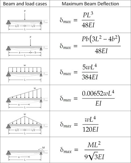
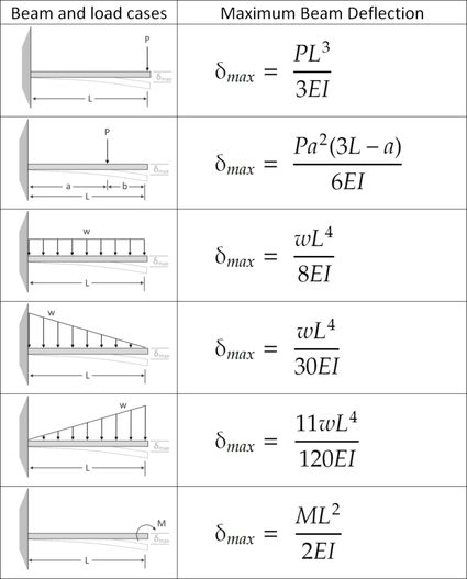
There are several types of beams, including simply supported beams, cantilever beams, and fixed-ended beams. Each type of beam has its own unique boundary conditions and load-carrying capacity. The loads applied to a beam can be point loads, uniformly distributed loads, or tapering loads. The tapering load is a type of load that varies along the length of the beam.
Stress Deflection Moment Equations
The stress deflection moment equations for a beam supported with partial tapering load applied can be derived using the beam equation and boundary conditions. The bending moment and shear force diagrams can be used to calculate the stress deflection moment. The deflection curve of the beam can be obtained by integrating the bending moment equation.
| Parameter | Symbol | Unit |
|---|---|---|
| Bending Moment | M | Nm |
| Shear Force | V | N |
| Deflection | y | m |
| Load | P | N |
| Length | L | m |
Calculator for Beam Supported Partial Tapering Load Applied
A calculator can be used to simplify the calculation of stress deflection moment equations for a beam supported with partial tapering load applied. The calculator can take into account the geometry, material properties, and boundary conditions of the beam. The calculator can provide the bending moment, shear force, and deflection of the beam.
Applications and Limitations
The stress deflection moment equations for a beam supported with partial tapering load applied have numerous applications in civil engineering and mechanical engineering. However, there are also limitations to the use of these equations, such as the assumption of linear elasticity and small deflections. The equations may not be applicable to beams with nonlinear material behavior or large deflections.
What is the moment equation for beam deflection?
The moment equation for beam deflection is a mathematical expression that describes the relationship between the moment applied to a beam and its resulting deflection. This equation is commonly used in engineering and physics to analyze the behavior of beams under various loads. The moment equation is typically expressed as M = EI(d^2y/dx^2), where M is the moment, EI is the flexural rigidity, and d^2y/dx^2 is the curvature of the beam.
Derivation of the Moment Equation
The derivation of the moment equation involves the use of differential equations and integration. The equation is derived by considering the equilibrium of a small element of the beam and applying the principle of virtual work. The resulting equation is a second-order differential equation that relates the moment and curvature of the beam. Some key points to consider when deriving the moment equation include:
- The beam is assumed to be prismatic, meaning that its cross-sectional area and moment of inertia are constant along its length.
- The load applied to the beam is assumed to be static, meaning that it does not change over time.
- The material of the beam is assumed to be linearly elastic, meaning that it follows Hooke's law.
Applications of the Moment Equation
The moment equation has numerous applications in engineering and physics, including the design of bridges, buildings, and machinery. It is used to analyze the deflection and stress of beams under various loads, such as point loads, uniformly distributed loads, and moments. Some key applications of the moment equation include:
- Structural analysis: The moment equation is used to analyze the stability and strength of structures, such as bridges and buildings.
- Machine design: The moment equation is used to design machinery and mechanisms, such as gears and bearings.
- Vibration analysis: The moment equation is used to analyze the vibration of beams and structures.
Assumptions and Limitations
The moment equation is based on several assumptions and has some limitations. Some key assumptions include:
- The beam is assumed to be prismatic, meaning that its cross-sectional area and moment of inertia are constant along its length.
- The load applied to the beam is assumed to be static, meaning that it does not change over time.
- The material of the beam is assumed to be linearly elastic, meaning that it follows Hooke's law.
These assumptions can limit the accuracy of the moment equation in certain situations, such as when the beam is non-prismatic or the load is dynamic.
Boundary Conditions
The moment equation requires boundary conditions to be specified in order to solve for the deflection of the beam. These boundary conditions typically include the supports and constraints applied to the beam, such as fixed ends or simply supported ends. Some key boundary conditions include:
- Fixed ends: The beam is fixed at both ends, meaning that it cannot translate or rotate.
- Simply supported ends: The beam is supported at both ends, meaning that it can translate but not rotate.
- Free ends: The beam is free at both ends, meaning that it can translate and rotate.
Solution Methods
The moment equation can be solved using various methods, including analytical and numerical methods. Some key solution methods include:
- Integration: The moment equation can be solved by integrating the equation to find the deflection of the beam.
- Finite element method: The moment equation can be solved using the finite element method, which involves discretizing the beam into small elements and solving for the deflection of each element.
- Numerical integration: The moment equation can be solved using numerical integration, which involves approximating the deflection of the beam using numerical methods.
These solution methods can be used to find the deflection and stress of beams under various loads, and are an essential part of engineering and physics. The moment equation is a fundamental concept in these fields, and is used to analyze the behavior of beams and structures. The equation is often used in conjunction with other equations, such as the equilibrium equation and the compatibility equation, to solve problems in engineering and physics. The solution of the moment equation can be used to determine the deflection and stress of beams and structures, and is an important part of design and analysis. The moment equation is a powerful tool for engineers and physicists, and is used to solve a wide range of problems in these fields.
What is the EI formula for deflection?

The EI formula for deflection is a mathematical equation used to calculate the deflection of a beam under load. The formula is: δ = (W L^3) / (3 E I), where δ is the deflection, W is the load, L is the length of the beam, E is the modulus of elasticity, and I is the moment of inertia.
Understanding the EI Formula
The EI formula is a fundamental concept in structural analysis and is used to design and analyze beams, columns, and other structural elements. To apply the formula, one needs to understand the properties of the material, such as the modulus of elasticity, and the geometry of the beam, including the length and moment of inertia.
- The modulus of elasticity is a measure of the material's stiffness and is typically denoted by the symbol E.
- The moment of inertia is a measure of the beam's resistance to bending and is typically denoted by the symbol I.
- The load and length of the beam are also critical factors in determining the deflection.
Applications of the EI Formula
The EI formula has numerous practical applications in engineering and construction. It is used to design and analyze beams, columns, and other structural elements, as well as to determine the stress and strain on these elements.
- The formula is used in building design to ensure that structures can support the weight of the building and any external loads.
- It is also used in bridge design to determine the deflection of the bridge under load.
- In mechanical engineering, the formula is used to design and analyze shafts, axles, and other rotating components.
Limitations of the EI Formula
While the EI formula is a powerful tool for calculating deflection, it has some limitations. The formula assumes that the beam is straight and homogeneous, and that the load is uniformly distributed. In reality, beams may be curved or tapered, and the load may be concentrated or non-uniform.
- The formula also assumes that the material is linear elastic, meaning that it follows Lame's equation.
- In non-linear materials, the formula may not be accurate, and more complex analysis may be required.
- The formula also does not account for damping or friction, which can affect the deflection of the beam.
Derivation of the EI Formula
The EI formula can be derived from the equations of motion for a beam under load. The derivation involves integrating the equation for the bending moment to obtain the equation for the deflection.
- The derivation assumes that the beam is in equilibrium, meaning that the sum of the forces and moments is zero.
- The derivation also assumes that the material is isotropic, meaning that its properties are the same in all directions.
- The resulting formula is a second-order differential equation that can be solved to obtain the deflection of the beam.
Using the EI Formula in Real-World Scenarios
The EI formula is widely used in real-world scenarios to design and analyze structures and machines. For example, it can be used to determine the deflection of a bridge under load, or to calculate the stress on a shaft in a machine.
- In aerospace engineering, the formula is used to design and analyze aircraft and spacecraft structures.
- In civil engineering, the formula is used to design and analyze buildings, bridges, and roads.
- In mechanical engineering, the formula is used to design and analyze machines, engines, and gearboxes.
How to find the deflection of a fixed beam?
To find the deflection of a fixed beam, you need to consider the load applied to the beam, the length of the beam, and the material properties of the beam. The deflection can be calculated using various formulas and equations, depending on the type of load and the boundary conditions of the beam. For a fixed beam, the deflection is typically calculated using the Euler-Bernoulli beam theory, which assumes that the beam is slender and that the deflection is small compared to the length of the beam.
Understanding Beam Theory
The Euler-Bernoulli beam theory is a fundamental concept in mechanics of materials that helps to calculate the deflection of a beam. The theory assumes that the beam is subjected to a load that causes bending and deflection. To calculate the deflection, you need to consider the following factors:
- The load applied to the beam, including the magnitude and distribution of the load.
- The length and cross-sectional area of the beam, which affect the stiffness and strength of the beam.
- The material properties of the beam, including the modulus of elasticity and Poisson's ratio.
Calculating Deflection using Formulas
The deflection of a fixed beam can be calculated using various formulas, including the Euler-Bernoulli beam equation, which is given by: δ = (WL^3) / (3EI), where δ is the deflection, W is the load, L is the length of the beam, E is the modulus of elasticity, and I is the moment of inertia. To calculate the deflection, you need to:
- Calculate the moment of inertia of the beam, which depends on the cross-sectional area and shape of the beam.
- Determine the load applied to the beam, including the magnitude and distribution of the load.
- Apply the Euler-Bernoulli beam equation to calculate the deflection.
Considering Boundary Conditions
The deflection of a fixed beam also depends on the boundary conditions, which include the supports and constraints applied to the beam. For a fixed beam, the boundary conditions are typically fixed-fixed, meaning that the beam is supported at both ends and constrained against rotation and translation. To consider the boundary conditions, you need to:
- Determine the type of supports and constraints applied to the beam.
- Apply the boundary conditions to the Euler-Bernoulli beam equation to calculate the deflection.
- Consider the effect of the boundary conditions on the stiffness and strength of the beam.
Using Numerical Methods
In addition to formulas and equations, numerical methods can also be used to calculate the deflection of a fixed beam. Numerical methods, such as the finite element method, can be used to model and analyze the behavior of the beam under various loads and boundary conditions. To use numerical methods, you need to:
- Model the beam using a finite element model, including the geometry, material properties, and boundary conditions.
- Apply the load to the beam and analyze the results using software or code.
- Validate the results by comparing them to experimental data or analytical solutions.
Accounting for Nonlinear Effects
The deflection of a fixed beam can also be affected by nonlinear effects, such as large deformations and material nonlinearity. To account for nonlinear effects, you need to:
- Model the beam using a nonlinear finite element model, including the geometry, material properties, and boundary conditions.
- Apply the load to the beam and analyze the results using software or code.
- Consider the effect of nonlinear effects on the stiffness and strength of the beam, including the possibility of buckling or failure.
How do you calculate the bending moment of a beam?
To calculate the bending moment of a beam, you need to consider the external loads acting on the beam, such as point loads, uniformly distributed loads, or moment loads. The bending moment is a measure of the flexural stress that occurs in the beam due to these external loads. It is calculated by taking the integral of the shear force diagram with respect to the length of the beam.
Understanding the Bending Moment Diagram
The bending moment diagram is a graphical representation of the bending moment along the length of the beam. To calculate the bending moment, you need to understand the sign convention, which states that positive bending moments occur when the beam is in tension on the top and compression on the bottom, and negative bending moments occur when the beam is in compression on the top and tension on the bottom. The key steps to calculate the bending moment are:
- Draw the free-body diagram of the beam to identify the external loads and support reactions.
- Calculate the shear force at each point along the length of the beam using the equilibrium equations.
- Integrate the shear force diagram to obtain the bending moment diagram.
Types of Loads and Their Effects on Bending Moment
Different types of loads have different effects on the bending moment of a beam. For example, point loads cause a step change in the bending moment, while uniformly distributed loads cause a linear change in the bending moment. The moment load causes a constant change ... in the bending moment. Some key points to consider when analyzing the effect of loads on bending moment are:
- Point loads cause a sudden change in the bending moment at the point of application.
- Uniformly distributed loads cause a gradual change in the bending moment along the length of the beam.
- Moment loads cause a constant change in the bending moment along the length of the beam.
Calculating Bending Moment Using the Moment-Area Method
The moment-area method is a powerful tool for calculating the bending moment of a beam. This method involves calculating the area under the moment diagram to obtain the bending moment. Some key steps to calculate the bending moment using the moment-area method are:
- Draw the moment diagram to visualize the bending moment along the length of the beam.
- Calculate the area under the moment diagram using integration or numerical methods.
- Use the moment-area theorem to relate the area under the moment diagram to the bending moment.
Using Beam Formulas to Calculate Bending Moment
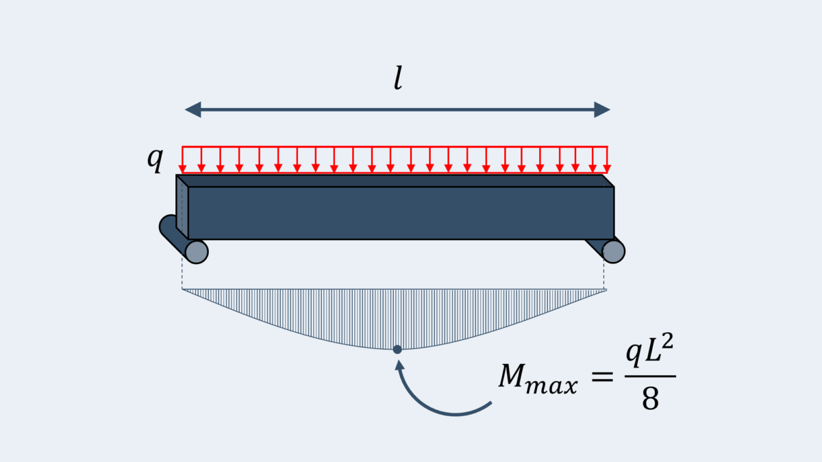
Beam formulas provide a quick and easy way to calculate the bending moment of a beam for common loading conditions. For example, the simple beam formula can be used to calculate the bending moment for a simply supported beam with a uniformly distributed load. Some key beam formulas to calculate bending moment are:
- The simple beam formula: M = (w L^2) / 8, where M is the bending moment, w is the uniformly distributed load, and L is the length of the beam.
- The cantilever beam formula: M = (w L^2) / 2, where M is the bending moment, w is the uniformly distributed load, and L is the length of the beam.
- The fixed beam formula: M = (w L^2) / 12, where M is the bending moment, w is the uniformly distributed load, and L is the length of the beam.
Software Tools for Calculating Bending Moment
There are many software tools available to calculate the bending moment of a beam, including finite element analysis software, beam analysis software, and spreadsheet software. Some key features to consider when selecting a software tool for calculating bending moment are:
- Accuracy: The software should be able to accurately calculate the bending moment for complex loading conditions.
- Ease of use: The software should be easy to use and require minimal input from the user.
- Visualization: The software should be able to visualize the bending moment diagram and other results in a clear and concise manner.
Frequently Asked Questions (FAQs)
What is the purpose of the Stress Deflection Moment Equations and Calculator for a beam supported with partial tapering load applied?
The Stress Deflection Moment Equations and Calculator is a tool used to calculate the stress and deflection of a beam that is supported with a partial tapering load applied. The purpose of this calculator is to provide engineers and designers with a quick and accurate way to determine the structural integrity of a beam under various loading conditions. By using the calculator, users can input the dimensions and material properties of the beam, as well as the load applied, to calculate the maximum stress and deflection of the beam. This information is crucial in ensuring that the beam can withstand the applied loads and maintain its structural integrity. The calculator takes into account the partial tapering of the load, which means that the load is not uniformly distributed along the length of the beam. This type of loading is common in many engineering applications, such as bridge design and building construction.
How do the Stress Deflection Moment Equations and Calculator account for the partial tapering load applied to the beam?
The Stress Deflection Moment Equations and Calculator accounts for the partial tapering load applied to the beam by using a combination of mathematical equations and algorithms. The calculator first determines the load distribution along the length of the beam, taking into account the partial tapering of the load. This is done using integrals and differential equations that describe the load-deflection behavior of the beam. The calculator then uses these equations to calculate the maximum stress and deflection of the beam at various points along its length. The calculator also takes into account the boundary conditions of the beam, such as the supports and constraints, to ensure that the calculations are accurate and realistic. By using a combination of mathematical and numerical methods, the calculator can provide highly accurate results for a wide range of loading conditions and beam configurations. The partial tapering load is a complex loading condition that requires advanced mathematical models to accurately predict the behavior of the beam.
What are the key factors that affect the stress and deflection of a beam supported with partial tapering load applied?
The key factors that affect the stress and deflection of a beam supported with partial tapering load applied are the dimensions and material properties of the beam, the load distribution and magnitude, and the boundary conditions of the beam. The dimensions of the beam, such as its length, width, and thickness, play a crucial role in determining the stress and deflection of the beam. The material properties, such as the young's modulus and poisson's ratio, also affect the behavior of the beam under load. The load distribution and magnitude are also critical factors, as they determine the amount of stress and deflection that the beam will experience. The boundary conditions, such as the supports and constraints, also play a significant role in determining the behavior of the beam. Other factors, such as the partial tapering of the load, can also affect the stress and deflection of the beam. By understanding these key factors, engineers and designers can use the Stress Deflection Moment Equations and Calculator to optimize the design of the beam and ensure its structural integrity.
How can the Stress Deflection Moment Equations and Calculator be used to optimize the design of a beam supported with partial tapering load applied?
The Stress Deflection Moment Equations and Calculator can be used to optimize the design of a beam supported with partial tapering load applied by providing a rapid and accurate way to evaluate the stress and deflection of the beam under various loading conditions. By using the calculator, engineers and designers can quickly iterate on different design options and parameters, such as the dimensions and material properties of the beam, to optimize its performance. The calculator can also be used to predict the behavior of the beam under different loading scenarios, allowing engineers and designers to identify potential weak points and optimize the design accordingly. Additionally, the calculator can be used to compare the performance of different design options, allowing engineers and designers to select the optimal design that meets the requirements and constraints of the project. By using the Stress Deflection Moment Equations and Calculator, engineers and designers can streamline the design process, reduce the risk of errors, and improve the overall quality of the design. The calculator is a powerful tool that can be used to optimize the design of a wide range of engineering applications, from bridge design to building construction.
Deja una respuesta
Entradas Relacionadas