
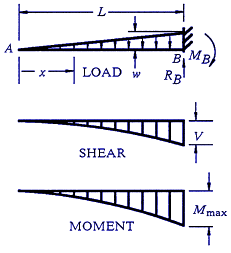
Beam Shear and Stress calculator for a Beam supported One End Cantilevered with Tapered Load
The calculation of beam shear and stress is crucial in engineering design, particularly for structures like cantilevered beams with tapered loads. A cantilevered beam supported at one end and subjected to a tapered load presents a complex scenario for stress analysis. This article introduces a calculator designed to simplify the process of determining beam shear and stress for such specific conditions, providing engineers with a streamlined tool to assess the structural integrity of their designs under these unique loading conditions. The calculator's functionality and application are discussed in detail, facilitating accurate calculations and informed design decisions.
- Beam Shear and Stress Calculator for a Beam Supported One End Cantilevered with Tapered Load
- How to calculate shear stress of cantilever beam?
- How do you calculate the bending stress of a cantilever beam?
- How do you calculate the load on a cantilever beam?
- What is the formula for cantilever beam?
-
Frequently Asked Questions (FAQs)
- What is the purpose of the Beam Shear and Stress calculator for a Beam supported One End Cantilevered with Tapered Load?
- How does the Beam Shear and Stress calculator handle the tapered load applied to the beam?
- What are the key inputs required to use the Beam Shear and Stress calculator?
- How can the results from the Beam Shear and Stress calculator be used in engineering design and analysis?
Beam Shear and Stress Calculator for a Beam Supported One End Cantilevered with Tapered Load
The Beam Shear and Stress calculator is a useful tool for engineers and designers to determine the shear forces and stresses acting on a beam that is supported at one end and has a tapered load. This type of beam is commonly used in construction, bridges, and other structural applications. The calculator takes into account the beam's length, cross-sectional area, material properties, and load distribution to provide accurate calculations.
Introduction to Beam Shear and Stress Calculator
The Beam Shear and Stress calculator is based on the theory of bending and shear deformation. It uses the beam's geometry and material properties to calculate the shear forces and stresses acting on the beam. The calculator is designed to handle tapered loads, which are common in many structural applications. The tapered load is applied to the beam, and the calculator determines the shear forces and stresses at different points along the beam.
Calculating Shear Forces and Stresses
To calculate the shear forces and stresses, the Beam Shear and Stress calculator uses the following formulas:
- Shear force: V = (w x L) / 2
- Shear stress: τ = V / A
- Bending moment: M = (w x L^2) / 8
- Bending stress: σ = M / I
where V is the shear force, w is the load per unit length, L is the beam's length, A is the cross-sectional area, τ is the shear stress, M is the bending moment, I is the moment of inertia, and σ is the bending stress.
Beam Geometry and Material Properties
The Beam Shear and Stress calculator requires the following beam geometry and material properties:
- Beam length: The length of the beam
- Cross-sectional area: The area of the beam's cross-section
- Moment of inertia: The moment of inertia of the beam's cross-section
- Material density: The density of the beam's material
- Young's modulus: The Young's modulus of the beam's material
- Poisson's ratio: The Poisson's ratio of the beam's material
Load Distribution and Tapered Load
The Beam Shear and Stress calculator can handle tapered loads, which are common in many structural applications. The tapered load is applied to the beam, and the calculator determines the shear forces and stresses at different points along the beam. The load distribution is used to calculate the shear forces and stresses.
Example Calculations and Results
The following table shows an example calculation using the Beam Shear and Stress calculator:
| Beam Length | Cross-Sectional Area | Load per Unit Length | Shear Force | Shear Stress |
|---|---|---|---|---|
| 10 m | 0.1 m^2 | 500 N/m | 2500 N | 25 MPa |
The calculator provides accurate calculations of the shear forces and stresses acting on the beam, which is essential for designing and analyzing structural systems. The results can be used to determine the beam's safety factor and design requirements. The calculator is a valuable tool for engineers and designers working with beams and structural systems.
How to calculate shear stress of cantilever beam?

To calculate the shear stress of a cantilever beam, you need to understand the concept of shear force and bending moment. The shear force is the force that causes the beam to deform by sliding along a plane parallel to the direction of the force, while the bending moment is the force that causes the beam to bend. The shear stress is calculated using the shear force and the cross-sectional area of the beam.
Understanding the Cantilever Beam
The cantilever beam is a type of beam that is fixed at one end and free at the other end. To calculate the shear stress of a cantilever beam, you need to understand the loading conditions and the geometry of the beam. The loading conditions include the load applied to the beam, the distance from the fixed end to the point of application of the load, and the angle of application of the load. The geometry of the beam includes the length, width, and height of the beam.
- Determine the loading conditions, including the load applied to the beam, the distance from the fixed end to the point of application of the load, and the angle of application of the load.
- Calculate the shear force and bending moment at the point of interest using the loading conditions and the geometry of the beam.
- Calculate the shear stress using the shear force and the cross-sectional area of the beam.
Calculating Shear Force and Bending Moment
The shear force and bending moment are calculated using the loading conditions and the geometry of the beam. The shear force is calculated by summing the forces acting on the beam, while the bending moment is calculated by summing the moments acting on the beam.
- Calculate the shear force at the point of interest using the loading conditions and the geometry of the beam.
- Calculate the bending moment at the point of interest using the loading conditions and the geometry of the beam.
- Use the shear force and bending moment to calculate the shear stress using the cross-sectional area of the beam.
Determining Cross-Sectional Area
The cross-sectional area of the beam is an important parameter in calculating the shear stress. The cross-sectional area is calculated by multiplying the width and height of the beam.
- Determine the width and height of the beam.
- Calculate the cross-sectional area by multiplying the width and height of the beam.
- Use the cross-sectional area to calculate the shear stress using the shear force.
Applying the Shear Stress Formula
The shear stress formula is used to calculate the shear stress of the beam. The shear stress formula is given by τ = V / A, where τ is the shear stress, V is the shear force, and A is the cross-sectional area.
- Calculate the shear force at the point of interest using the loading conditions and the geometry of the beam.
- Calculate the cross-sectional area of the beam using the width and height of the beam.
- Apply the shear stress formula to calculate the shear stress using the shear force and cross-sectional area.
Considering the Effects of Bending Moment
The bending moment also affects the shear stress of the beam. The bending moment causes the beam to bend, which in turn affects the shear stress.
- Calculate the bending moment at the point of interest using the loading conditions and the geometry of the beam.
- Determine the effect of the bending moment on the shear stress.
- Use the bending moment to calculate the combined stress using the shear stress and normal stress.
How do you calculate the bending stress of a cantilever beam?

To calculate the bending stress of a cantilever beam, you need to use the beam's geometry, the applied load, and the material's properties. The bending stress can be calculated using the formula: σ = (M c) / I, where σ is the bending stress, M is the maximum moment, c is the distance from the neutral axis to the extreme fiber, and I is the moment of inertia. The maximum moment can be calculated using the formula: M = (P L) / 2, where P is the applied load and L is the length of the beam.
Understanding the Bending Stress Formula
The bending stress formula is based on the beam theory, which assumes that the beam is subjected to a pure bending moment. The formula takes into account the material's properties, such as the Young's modulus, and the beam's geometry, including the cross-sectional area and the moment of inertia. To apply the formula, you need to calculate the maximum moment and the distance from the neutral axis to the extreme fiber. This can be done using the following steps:
- Calculate the maximum moment using the formula: M = (P L) / 2
- Calculate the distance from the neutral axis to the extreme fiber using the formula: c = (h / 2), where h is the height of the beam
- Calculate the moment of inertia using the formula: I = (b h^3) / 12, where b is the width of the beam
Calculating the Moment of Inertia
The moment of inertia is a measure of the beam's resistance to bending. It depends on the beam's geometry, including the cross-sectional area and the height. To calculate the moment of inertia, you need to know the beam's dimensions, including the width and height. The formula for the moment of inertia is: I = (b h^3) / 12. This formula is based on the beam theory, which assumes that the beam is a prismatic beam with a constant cross-sectional area.
- Calculate the width of the beam: b
- Calculate the height of the beam: h
- Calculate the moment of inertia using the formula: I = (b h^3) / 12
Applying the Bending Stress Formula
The bending stress formula can be applied to a variety of beam configurations, including cantilever beams, simply supported beams, and fixed-fixed beams. To apply the formula, you need to calculate the maximum moment and the distance from the neutral axis to the extreme fiber. You also need to know the material's properties, such as the Young's modulus.
- Calculate the maximum moment using the formula: M = (P L) / 2
- Calculate the distance from the neutral axis to the extreme fiber using the formula: c = (h / 2)
- Calculate the bending stress using the formula: σ = (M c) / I
Considering the Material's Properties
The material's properties play a crucial role in the calculation of the bending stress. The Young's modulus is a measure of the material's stiffness, while the Poisson's ratio is a measure of the material's lateral strain. To calculate the bending stress, you need to know the material's properties, including the Young's modulus and the Poisson's ratio.
- Look up the material's properties, including the Young's modulus and the Poisson's ratio
- Calculate the bending stress using the formula: σ = (M c) / I
- Check the material's strength to ensure that it can withstand the calculated bending stress
Using the Beam Theory Assumptions
The beam theory assumptions are used to simplify the calculation of the bending stress. The assumptions include the prismatic beam assumption, which states that the beam has a constant cross-sectional area, and the pure bending assumption, which states that the beam is subjected to a pure bending moment. To apply the beam theory assumptions, you need to ensure that the beam meets the assumptions, including the prismatic beam assumption and the pure bending assumption.
- Check the beam's geometry to ensure that it meets the prismatic beam assumption
- Check the applied load to ensure that it meets the pure bending assumption
- Apply the beam theory assumptions to simplify the calculation of the bending stress
How do you calculate the load on a cantilever beam?
To calculate the load on a cantilever beam, you need to consider the weight of the beam itself, as well as any external loads that are applied to it. This includes point loads, uniformly distributed loads, and moments. The first step is to determine the reactions at the supports, which can be done using equilibrium equations. Once the reactions are known, you can use beam theory to calculate the shear force and bending moment diagrams, which will give you the maximum stress and deflection of the beam.
Understanding Cantilever Beam Theory
The cantilever beam is a type of beam that is supported at one end and free at the other. To calculate the load on a cantilever beam, you need to understand the theory behind it. This includes knowing the beam's length, cross-sectional area, and material properties. The load on the beam can be calculated using the following steps:
- Calculate the weight of the beam itself
- Determine the external loads applied to the beam
- Calculate the reactions at the supports using equilibrium equations
Calculating Reactions at Supports
The reactions at the supports are the forces and moments that the support applies to the beam. To calculate these reactions, you need to use equilibrium equations, which state that the sum of all forces and moments acting on the beam must be equal to zero. This can be done by drawing a free body diagram of the beam and applying the equilibrium equations. The reactions can be calculated using the following steps:
- Draw a free body diagram of the beam
- Apply the equilibrium equations to the beam
- Calculate the reactions at the supports
Determining External Loads
The external loads applied to the beam can be point loads, uniformly distributed loads, or moments. To calculate the load on the beam, you need to know the magnitude and location of these external loads. The external loads can be calculated using the following steps:
- Identify the type of external load applied to the beam
- Determine the magnitude of the external load
- Calculate the location of the external load
Calculating Shear Force and Bending Moment Diagrams
The shear force and bending moment diagrams are used to calculate the maximum stress and deflection of the beam. To calculate these diagrams, you need to use beam theory, which states that the shear force and bending moment are related to the load and support reactions. The shear force and bending moment diagrams can be calculated using the following steps:
- Calculate the shear force diagram using the load and support reactions
- Calculate the bending moment diagram using the shear force diagram
- Determine the maximum stress and deflection of the beam
Applying Safety Factors and Codes
When calculating the load on a cantilever beam, you need to apply safety factors and codes to ensure that the beam is safe and durable. This includes using material safety factors, load factors, and design codes. The safety factors and codes can be applied using the following steps:
- Determine the material safety factor for the beam
- Apply the load factor to the external loads
- Use design codes to ensure that the beam meets the required standards
What is the formula for cantilever beam?

The formula for a cantilever beam is a mathematical expression that describes the behavior of a beam that is fixed at one end and free at the other. The formula is used to calculate the deflection, stress, and strain of the beam under various types of loads. The most common formula for a cantilever beam is the Euler-Bernoulli beam theory, which is a simplification of the more complex beam theory. This formula is widely used in engineering and architecture to design and analyze beams, frames, and other structures.
Types of Loads on a Cantilever Beam
The type of load on a cantilever beam can significantly affect its behavior. The following are some of the most common types of loads:
- Point load: a load that is applied at a single point on the beam
- Uniformly distributed load: a load that is applied evenly along the length of the beam
- Linearly varying load: a load that varies linearly along the length of the beam
These loads can cause bending, tension, and compression in the beam, which can lead to deflection and failure if not properly designed.
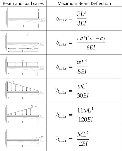
Deflection of a Cantilever Beam
The deflection of a cantilever beam is the amount of bending or curvature that occurs under a load. The deflection can be calculated using the formula: δ = (W L^3) / (3 E I), where δ is the deflection, W is the load, L is the length of the beam, E is the modulus of elasticity, and I is the moment of inertia. The deflection can be affected by the material properties, beam size, and load type.
Stress and Strain in a Cantilever Beam
The stress and strain in a cantilever beam are critical parameters that must be considered in design. The stress can be calculated using the formula: σ = (M y) / I, where σ is the stress, M is the bending moment, y is the distance from the neutral axis, and I is the moment of inertia. The strain can be calculated using the formula: ε = (σ L) / (E I), where ε is the strain. The stress and strain can cause failure if they exceed the material limits.
Boundary Conditions of a Cantilever Beam
The boundary conditions of a cantilever beam are the conditions that the beam must satisfy at its ends. The most common boundary conditions are:
- Fixed end: the beam is fixed at one end and cannot move or rotate
- Free end: the beam is free at one end and can move or rotate
- Simply supported end: the beam is supported at one end and can rotate but not move
These boundary conditions can affect the deflection, stress, and strain of the beam.
Applications of Cantilever Beams
Cantilever beams have a wide range of applications in engineering and architecture, including:
- Bridges: cantilever beams are used in bridge design to span long distances
- Buildings: cantilever beams are used in building design to create overhangs and balconies
- Machinery: cantilever beams are used in machine design to create levers and linkages
The cantilever beam formula is essential in these applications to ensure that the beam can withstand the loads and stresses imposed on it.
Frequently Asked Questions (FAQs)
What is the purpose of the Beam Shear and Stress calculator for a Beam supported One End Cantilevered with Tapered Load?
The Beam Shear and Stress calculator is a tool designed to calculate the shear forces and stresses that occur in a beam that is supported at one end and has a tapered load applied to it. The calculator takes into account the length of the beam, the load applied, and the material properties of the beam to determine the maximum shear force and maximum stress that occur in the beam. This information is critical for engineers and designers to ensure that the beam is able to withstand the applied loads and to prevent failure. The calculator is particularly useful for designing cantilevered beams with tapered loads, which are commonly found in structural engineering applications.
How does the Beam Shear and Stress calculator handle the tapered load applied to the beam?
The Beam Shear and Stress calculator handles the tapered load applied to the beam by using a mathematical model that takes into account the variation in load along the length of the beam. The calculator uses the principle of superposition to calculate the shear forces and stresses at each point along the beam, taking into account the linear variation in load. The calculator also allows users to input the load intensity and load distribution along the beam, which enables it to accurately calculate the maximum shear force and maximum stress that occur in the beam. By using a tapered load model, the calculator provides a more accurate representation of the real-world loading conditions that the beam will experience.
What are the key inputs required to use the Beam Shear and Stress calculator?
To use the Beam Shear and Stress calculator, users need to input several key parameters, including the length of the beam, the load intensity and load distribution along the beam, and the material properties of the beam, such as its modulus of elasticity and yield strength. Additionally, users need to specify the boundary conditions of the beam, including the support conditions at the fixed end and the load application point. The calculator also requires users to input the units of measurement for each parameter, such as length, force, and stress. By providing these key inputs, users can obtain accurate calculations of the shear forces and stresses that occur in the beam, which is essential for ensuring the structural integrity of the beam.
How can the results from the Beam Shear and Stress calculator be used in engineering design and analysis?
The results from the Beam Shear and Stress calculator can be used in engineering design and analysis to ensure that the beam is able to withstand the applied loads and to prevent failure. The calculated shear forces and stresses can be used to determine the required section properties of the beam, such as its moment of inertia and section modulus. The results can also be used to optimize the design of the beam, by minimizing its weight and cost while still ensuring that it meets the required structural integrity and safety standards. Additionally, the results can be used to validate the performance of the beam under different loading conditions, which is critical for ensuring the reliability and safety of the structure. By using the results from the calculator, engineers and designers can create safe, efficient, and cost-effective designs that meet the required structural and functional requirements.
Deja una respuesta
Entradas Relacionadas