
Wind Force on Flag Pole Cylinder Formula and Calculator
The wind force exerted on a flag pole cylinder is a fundamental concept in engineering and architecture. As wind flows around the cylinder, it creates a pressure difference, resulting in a force that can cause structural damage or instability. The calculation of this force is crucial in designing and installing flag poles, especially in areas prone to high winds. The formula to calculate wind force on a flag pole cylinder takes into account factors such as wind speed, air density, and cylinder diameter, providing a reliable estimate of the force exerted.
- Wind Force on Flag Pole Cylinder Formula and Calculator
- How do you calculate wind force on a cylinder?
- How to calculate wind load on flagpole?
- What is the formula for pole wind load?
-
What is the formula for the flag pole?
- Design Considerations
- The materials used for the flag pole can vary, but common options include aluminum, fiberglass, and wood. Each material has its own strengths and weaknesses, and the choice will depend on the specific needs and requirements of the project. Some important considerations include: Aluminum is a popular choice for flag poles due to its lightweight and corrosion-resistant properties. Fiberglass is another option, offering high strength and durability. Wood is a traditional choice for flag poles, but requires regular maintenance to prevent rot and decay. Flag Pole Installation
- Flag Pole Maintenance
- Flag Pole Safety
-
Frequently Asked Questions (FAQs)
- What is the Wind Force on Flag Pole Cylinder Formula and how is it calculated?
- How does the Wind Force on Flag Pole Cylinder Calculator work and what are its limitations?
- What are the factors that affect the Wind Force on a Flag Pole Cylinder and how can they be mitigated?
- How can the Wind Force on Flag Pole Cylinder Formula and Calculator be used in real-world applications?
Wind Force on Flag Pole Cylinder Formula and Calculator
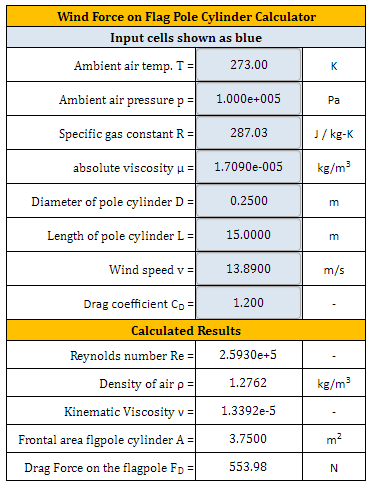
The wind force on a flag pole cylinder is a critical parameter in determining the structural integrity and stability of the flag pole. The force exerted by the wind on the cylinder can be calculated using the formula: F = 0.5 ρ v^2 A Cd, where F is the force, ρ is the air density, v is the wind velocity, A is the cross-sectional area of the cylinder, and Cd is the drag coefficient. This formula is widely used in engineering and architectural applications to calculate the wind load on structures.
Introduction to Wind Force Calculation
The calculation of wind force on a flag pole cylinder is essential to ensure that the structure can withstand various wind conditions. The wind velocity and air density are critical parameters that affect the wind force. The wind velocity is typically measured in meters per second (m/s) or miles per hour (mph), while the air density is usually measured in kilograms per cubic meter (kg/m^3). The drag coefficient (Cd) is a dimensionless quantity that depends on the shape and size of the cylinder.
Flag Pole Cylinder Geometry and Wind Force
The geometry of the flag pole cylinder plays a significant role in determining the wind force. The cylinder diameter and height are critical parameters that affect the wind load. A larger cylinder diameter and height result in a greater wind force. The aspect ratio of the cylinder, which is the ratio of the height to the diameter, also influences the wind force. A higher aspect ratio results in a lower wind force.
Wind Force Calculation Formula and Variables
The wind force calculation formula involves several variables, including the wind velocity, air density, cylinder diameter, cylinder height, and drag coefficient. The formula is: F = 0.5 ρ v^2 A Cd, where F is the force, ρ is the air density, v is the wind velocity, A is the cross-sectional area of the cylinder, and Cd is the drag coefficient. The cross-sectional area (A) is calculated as A = π (d/2)^2, where d is the cylinder diameter.
Calculation Examples and Wind Force Calculator
To calculate the wind force on a flag pole cylinder, we can use the formula: F = 0.5 ρ v^2 A Cd. For example, if the wind velocity is 10 m/s, the air density is 1.2 kg/m^3, the cylinder diameter is 0.5 m, the cylinder height is 10 m, and the drag coefficient is 0.5, the wind force can be calculated as: F = 0.5 1.2 (10)^2 π (0.5/2)^2 0.5 = 123.4 N. A wind force calculator can be used to simplify the calculation process.
Wind Force Calculation Table and Parameters
The following table summarizes the wind force calculation parameters and formula:
| Parameter | Unit | Description |
|---|---|---|
| Wind Velocity | m/s or mph | The speed of the wind |
| Air Density | kg/m^3 | The density of the air |
| Cylinder Diameter | m | The diameter of the cylinder |
| Cylinder Height | m | The height of the cylinder |
| Drag Coefficient | dimensionless | The drag coefficient of the cylinder |
The wind force calculation formula is: F = 0.5 ρ v^2 A Cd, where F is the force, ρ is the air density, v is the wind velocity, A is the cross-sectional area of the cylinder, and Cd is the drag coefficient.
How do you calculate wind force on a cylinder?

To calculate the wind force on a cylinder, you need to consider the velocity of the wind, the density of the air, and the dimensions of the cylinder. The force exerted on the cylinder is given by the equation F = 0.5 ρ v^2 A Cd, where ρ is the air density, v is the wind velocity, A is the cross-sectional area of the cylinder, and Cd is the drag coefficient.
Understanding the Basics of Wind Force Calculation
The calculation of wind force on a cylinder involves understanding the aerodynamic properties of the cylinder and the wind conditions. The wind force is proportional to the square of the wind velocity, which means that even small increases in wind speed can result in significant increases in force. The drag coefficient (Cd) is a measure of the cylinder's ability to resist the wind force, with higher values indicating greater resistance.
- The density of the air is a critical factor in calculating the wind force.
- The dimensions of the cylinder, including its length and diameter, also play a role in determining the force exerted by the wind.
- The drag coefficient (Cd) is dependent on the shape and surface roughness of the cylinder.
Factors Influencing Wind Force Calculation
Several factors can influence the calculation of wind force on a cylinder, including the Reynolds number, which is a measure of! the turbulence of the flow. The surface roughness of the cylinder can also impact the drag coefficient, with smoother surfaces resulting in lower Cd values. Additionally, the orientation of the cylinder with respect to the wind direction can affect the force exerted by the wind.
- The Reynolds number is a critical factor in determining the turbulence of the flow.
- The surface roughness of the cylinder can impact the drag coefficient.
- The orientation of the cylinder with respect to the wind direction can affect the force exerted by the wind.
Applications of Wind Force Calculation
The calculation of wind force on a cylinder has numerous applications in engineering and design, including the design of buildings, bridges, and wind turbines. Accurate calculations of wind force are critical to ensuring the stability and safety of these structures. Additionally, wind force calculations can be used to optimize the performance of wind turbines and other aerodynamic devices.
- The design of buildings and bridges requires accurate calculations of wind force.
- The performance of wind turbines can be optimized through wind force calculations.
- Aerodynamic devices, such as aircraft and vehicles, also rely on wind force calculations.
Methods for Calculating Wind Force
There are several methods for calculating wind force on a cylinder, including empirical formulas, numerical simulations, and experimental measurements. Empirical formulas, such as the drag equation, provide a simplified approach to calculating wind force, while numerical simulations, such as computational fluid dynamics (CFD), offer a more detailed and accurate approach.
- Empirical formulas, such as the drag equation, provide a simplified approach to calculating wind force.
- Numerical simulations, such as computational fluid dynamics (CFD), offer a more detailed and accurate approach.
- Experimental measurements, such as wind tunnel tests, can be used to validate wind force calculations.
Challenges in Wind Force Calculation
Calculating wind force on a cylinder can be challenging due to the complexity of the flow and the variability of the wind conditions. The turbulence of the flow can make it difficult to predict the wind force, and the surface roughness of the cylinder can impact the drag coefficient. Additionally, the orientation of the cylinder with respect to the wind direction can affect the force exerted by the wind.
- The turbulence of the flow can make it difficult to predict the wind force.
- The surface roughness of the cylinder can impact the drag coefficient.
- The orientation of the cylinder with respect to the wind direction can affect the force exerted by the wind, which is influenced by strong wind and turbulent flow.
How to calculate wind load on flagpole?
To calculate the wind load on a flagpole, you need to consider several factors, including the height and diameter of the pole, the flag size and material, and the wind speed and direction. The wind load is the force exerted by the wind on the flagpole, and it can cause the pole to bend or break if it is not designed to withstand the load. The calculation of wind load involves using formulas and equations that take into account the various factors that affect the load.
Understanding Wind Load Factors
The calculation of wind load on a flagpole involves understanding the various factors that affect the load, including the density of the air, the velocity of the wind, and the shape and size of the flagpole. The wind load is also affected by the flag size and material, as well as the height and diameter of the pole.
- The flag size and material can affect the wind load, with larger flags and heavier materials resulting in a greater load.
- The height and diameter of the pole can also affect the wind load, with taller and thicker poles resulting in a greater load.
- The wind speed and direction can also affect the wind load, with higher wind speeds and more direct wind directions resulting in a greater load.
Calculating Wind Load Using Formulas
The wind load on a flagpole can be calculated using formulas and equations, such as the drag equation, which takes into account the density of the air, the velocity of the wind, and the shape and size of the flagpole. The lift equation can also be used to calculate the wind load, and it takes into account the flag size and material, as well as the height and diameter of the pole.
- The drag equation can be used to calculate the wind load, and it is given by the formula: FD = ½ ρ v^2 CD A, where FD is the drag force, ρ is the air density, v is the wind velocity, CD is the drag coefficient, and A is the flag area.
- The lift equation can also be used to calculate the wind load, and it is given by the formula: FL = ½ ρ v^2 CL A, where FL is the lift force, ρ is the air density, v is the wind velocity, CL is the lift coefficient, and A is the flag area.
- The resultant force can be calculated by combining the drag and lift forces, and it is given by the formula: FR = √(FD^2 + FL^2), where FR is the resultant force.
Designing a Flagpole to Withstand Wind Load
To design a flagpole that can withstand the wind load, you need to consider the materials and construction of the pole, as well as the flag size and material. The pole should be made of a strong and durable material, such as steel or aluminum, and it should be anchored securely to the ground. The flag should also be made of a lightweight and flexible material, such as nylon or polyester.
- The pole material should be chosen based on its strength and durability, as well as its weight and cost.
- The flag material should be chosen based on its weight and flexibility, as well as its color and design.
- The pole shape and size should be chosen based on the wind load and the flag size, as well as the aesthetics and visibility of the flagpole.
Testing and Certifying Flagpoles for Wind Load
To ensure that a flagpole can withstand the wind load, it should be tested and certified by a qualified testing laboratory or certification body. The testing should involve simulating the wind load on the flagpole, and measuring the deflection and stress on the pole. The certification should involve verifying that the flagpole meets the requirements and standards for wind load resistance.
- The testing should involve simulating the wind load on the flagpole using a wind tunnel or other testing equipment.
- The certification should involve verifying that the flagpole meets the requirements and standards for wind load resistance, such as those specified by the International Building Code or other building codes.
- The testing and certification should be performed by a qualified testing laboratory or certification body, such as the American Society for Testing and Materials or other reputable organizations.
Installing and Maintaining Flagpoles for Wind Load Resistance
To ensure that a flagpole can withstand the wind load, it should be installed and maintained properly. The installation should involve anchoring the pole securely to the ground, and aligning it properly with the wind direction. The maintenance should involve inspecting the pole regularly for damage or wear, and replacing any damaged or worn parts.
- The installation should involve anchoring the pole securely to the ground using a strong and durable anchor, such as a concrete or steel anchor.
- The maintenance should involve inspecting the pole regularly for damage or wear, and replacing any damaged or worn parts, such as the flag or halyard.
- The installation and maintenance should be performed by a qualified installer or maintenance personnel, such as a licensed contractor or other reputable professionals.
What is the formula for pole wind load?
The formula for pole wind load is a calculation used to determine the force exerted on a pole or structure by wind. The formula typically takes into account the wind speed, air density, and pole dimensions. The calculation involves using the drag coefficient and projected area of the pole to determine the wind load.
Introduction to Pole Wind Load Calculation
The pole wind load calculation is a critical step in designing and installing poles for various applications, such as wind turbines, antennas, and transmission lines. The calculation involves using a combination of mathematical formulas and engineering principles to determine the maximum wind load that the pole can withstand. This is essential to ensure the structural integrity and safety of the pole and surrounding structures.
- Use the ASCE 7-10 standard for wind load calculation
- Consider the topography and roughness of the surrounding area
- Account for the directionality of the wind and the pole's orientation
Factors Affecting Pole Wind Load
Several factors can affect the pole wind load, including the wind speed, air density, and pole dimensions. The shape and size of the pole, as well as its surface roughness, can also impact the wind load. Additionally, the surrounding terrain and obstacles can influence the wind flow and load on the pole.
- Consider the wind speed profile and turbulence
- Account for the pole's flexibility and damping characteristics
- Use computational fluid dynamics to model complex wind flows
Methods for Calculating Pole Wind Load
There are several methods for calculating pole wind load, including the analytical method, numerical method, and experimental method. The analytical method involves using mathematical formulas to calculate the wind load, while the numerical method uses computer simulations to model the wind flow and load. The experimental method involves physical testing and measurement of the wind load.
- Use the Gust Factor Approach for simple calculations
- Employ the Finite Element Method for complex simulations
- Conduct wind tunnel testing for experimental validation
Applications of Pole Wind Load Calculation
The pole wind load calculation has various applications in engineering and design, including wind turbines, transmission lines, and antennas. The calculation is essential for ensuring the structural integrity and safety of these structures, as well as optimizing their performance and efficiency.
- Design wind turbines for maximum energy production
- Optimize transmission line routing and tower design
- Develop antenna systems with high gain and directivity
Software and Tools for Pole Wind Load Calculation
Several software and tools are available for pole wind load calculation, including commercial and open-source options. These tools can help engineers and designers perform complex calculations and simulations, and optimize their designs for maximum performance and minimum cost.
- Use ADS for aerodynamic and structural analysis
- Employ ANSYS for finite element simulations
- Utilize OpenFOAM for computational fluid dynamics modeling
What is the formula for the flag pole?

The formula for the flag pole is not a specific mathematical equation, but rather a set of guidelines and considerations for designing and constructing a flag pole. The height and diameter of the pole, as well as the material and weight of the flag, are all important factors to consider when determining the overall design of the flag pole.
Design Considerations
When designing a flag pole, there are several key factors to consider, including the height and visibility of the pole, as well as the wind resistance and durability of the materials used. Some important considerations include:
- The height of the pole should be proportional to the size of the flag and the surrounding environment.
- The material used for the pole should be strong and durable, able to withstand wind and weather conditions.
- The weight of the flag should be taken into account, as it can affect the stability and balance of the pole.
The materials used for the flag pole can vary, but common options include aluminum, fiberglass, and wood. Each material has its own strengths and weaknesses, and the choice will depend on the specific needs and requirements of the project. Some important considerations include:
- Aluminum is a popular choice for flag poles due to its lightweight and corrosion-resistant properties.
- Fiberglass is another option, offering high strength and durability.
- Wood is a traditional choice for flag poles, but requires regular maintenance to prevent rot and decay.
Flag Pole Installation
The installation of the flag pole is a critical step in the process, requiring careful planning and execution. The pole must be securely anchored to the ground, using a strong and stable foundation. Some important considerations include:
- The foundation of the pole should be deep and wide enough to provide stability and support.
- The pole should be level and plumb, to ensure proper alignment and balance.
- The flag should be securely attached to the pole, using strong and durable fasteners.
Flag Pole Maintenance
Regular maintenance is essential to ensure the longevity and safety of the flag pole. This includes inspecting the pole and flag for damage and wear, as well as cleaning and lubricating the moving parts. Some important considerations include:
- The pole should be inspected regularly for signs of wear and damage.
- The flag should be cleaned and dried regularly to prevent mold and mildew.
- The hinges and pulleys should be lubricated regularly to ensure smooth operation.
Flag Pole Safety
The safety of the flag pole is a critical consideration, as it can pose a hazard to people and property if not properly installed and maintained. Some important considerations include:
- The pole should be designed and constructed to withstand strong winds and severe weather.
- The flag should be securely attached to the pole, using strong and durable fasteners.
- The area surrounding the pole should be clear of obstacles and hazards, to prevent accidents and injuries.
Frequently Asked Questions (FAQs)
What is the Wind Force on Flag Pole Cylinder Formula and how is it calculated?
The Wind Force on Flag Pole Cylinder Formula is a mathematical equation used to calculate the wind load on a cylindrical flag pole. This formula takes into account the velocity of the wind, the diameter and height of the flag pole, and the density of the air. The formula is typically expressed as F = 0.5 ρ v^2 C_d A, where F is the wind force, ρ is the air density, v is the wind velocity, C_d is the drag coefficient, and A is the projected area of the flag pole. To calculate the wind force, you need to know the values of these parameters and plug them into the formula. The result will give you the total wind force acting on the flag pole.
How does the Wind Force on Flag Pole Cylinder Calculator work and what are its limitations?
The Wind Force on Flag Pole Cylinder Calculator is an online tool that uses the formula mentioned earlier to calculate the wind force on a cylindrical flag pole. The calculator requires you to input the diameter, height, and material of the flag pole, as well as the wind speed and direction. The calculator then uses these inputs to calculate the wind force and displays the result in a user-friendly format. However, the calculator has some limitations, such as assuming a uniform wind flow and neglecting the effects of turbulence. Additionally, the calculator may not take into account other factors that can affect the wind load, such as the flag itself or the mounting hardware. Therefore, the results should be used as an approximation rather than an exact value.
What are the factors that affect the Wind Force on a Flag Pole Cylinder and how can they be mitigated?
There are several factors that can affect the wind force on a flag pole cylinder, including the wind speed, flag size, and flag material. A larger flag or a flag made of a heavy material can increase the wind load, while a smaller flag or a flag made of a lightweight material can reduce it. The height and diameter of the flag pole can also affect the wind load, with taller and thicker poles experiencing greater wind forces. To mitigate these effects, flag pole manufacturers can use reinforced materials, such as fiberglass or aluminum, to increase the strength and stability of the pole. Additionally, flag designers can use aerodynamic shapes and lightweight materials to reduce the wind load on the flag.
How can the Wind Force on Flag Pole Cylinder Formula and Calculator be used in real-world applications?
The Wind Force on Flag Pole Cylinder Formula and Calculator can be used in a variety of real-world applications, such as flag pole design, installation, and maintenance. Engineers and architects can use the formula and calculator to determine the structural integrity of a flag pole and ensure that it can withstand high winds and other environmental conditions. Flag pole manufacturers can use the formula and calculator to optimize their designs and reduce the weight and cost of their products. Additionally, building owners and facilities managers can use the formula and calculator to assess the wind load on their flag poles and schedule regular inspections and maintenance to ensure that their flag poles remain safe and secure. By using the Wind Force on Flag Pole Cylinder Formula and Calculator, professionals can make informed decisions and improve the performance and safety of their flag poles.
Deja una respuesta
Entradas Relacionadas