
Weld Shear Stress for Applied Torque on Solid Shaft Calculator

The Weld Shear Stress for Applied Torque on Solid Shaft Calculator is a valuable tool for engineers and mechanics. It calculates the shear stress that occurs when a torque is applied to a solid shaft, which is crucial in determining the shaft's ability to withstand the load. This calculator takes into account the torque, shaft diameter, and length to provide accurate results. By using this calculator, users can ensure the shaft's safety and efficiency, preventing potential failures and reducing maintenance costs. It is a reliable and efficient way to analyze and design shafts for various applications.
- Weld Shear Stress for Applied Torque on Solid Shaft Calculator
- What is the shear stress equation for solid shaft?
- How do you calculate the shear strength of a weld?
- What is the torsional stress of a solid shaft?
-
Frequently Asked Questions (FAQs)
- What is the purpose of the Weld Shear Stress for Applied Torque on Solid Shaft Calculator?
- How does the Weld Shear Stress for Applied Torque on Solid Shaft Calculator work?
- What are the limitations of the Weld Shear Stress for Applied Torque on Solid Shaft Calculator?
- How can I use the Weld Shear Stress for Applied Torque on Solid Shaft Calculator in my design process?
Weld Shear Stress for Applied Torque on Solid Shaft Calculator
The Weld Shear Stress for Applied Torque on Solid Shaft Calculator is a tool used to calculate the shear stress that occurs in a solid shaft when a torque is applied. This calculator is essential in the field of mechanical engineering and materials science, as it helps design and analyze shafts and other mechanical components that are subjected to torsional loads.
Introduction to Weld Shear Stress
Weld shear stress is a type of stress that occurs when a welded joint is subjected to a shear force. In the context of a solid shaft, weld shear stress occurs when a torque is applied, causing the shaft to twist and resulting in a shear deformation. The Weld Shear Stress for Applied Torque on Solid Shaft Calculator takes into account the material properties of the shaft, such as its yield strength and ultimate strength, as well as the geometric parameters of the shaft, such as its diameter and length.
Calculating Weld Shear Stress
To calculate the weld shear stress, the calculator uses the following formula: τ = (16 T) / (π d^3), where τ is the shear stress, T is the applied torque, and d is the diameter of the shaft. This formula assumes that the shaft is solid and circular, and that the torque is applied uniformly. The calculator also takes into account the units of the input values, such as newton-meters for torque and millimeters for diameter.
Factors Affecting Weld Shear Stress
Several factors can affect the weld shear stress, including the material properties of the shaft, the geometric parameters of the shaft, and the applied torque. For example, a shaft made of a stronger material will be able to withstand a higher torque without failing, while a shaft with a larger diameter will be less prone to shear deformation. The calculator takes these factors into account to provide an accurate calculation of the weld shear stress.
Applications of the Weld Shear Stress Calculator
The Weld Shear Stress for Applied Torque on Solid Shaft Calculator has several applications in the field of mechanical engineering and materials science. For example, it can be used to design and analyze shafts and other mechanical components, such as gears and bearings, that are subjected to torsional loads. It can also be used to optimize the design of these components to minimize weight and cost while maintaining strength and reliability.
Limitations of the Weld Shear Stress Calculator
The Weld Shear Stress for Applied Torque on Solid Shaft Calculator has several limitations, including the assumption that the shaft is solid and circular, and that the torque is applied uniformly. Additionally, the calculator does not take into account other types of loads, such as bending and tension, that may be applied to the shaft. The calculator also assumes that the material properties of the shaft are isotropic, meaning that they are the same in all directions.
| Parameter | Unit | Description |
|---|---|---|
| Torque (T) | newton-meters (Nm) | The torque applied to the shaft |
| Diameter (d) | millimeters (mm) | The diameter of the shaft |
| Shear Stress (τ) | pascals (Pa) | The shear stress that occurs in the shaft |
| Yield Strength (σy) | pascals (Pa) | The yield strength of the shaft material |
| Ultimate Strength (σu) | pascals (Pa) | The ultimate strength of the shaft material |
What is the shear stress equation for solid shaft?

The shear stress equation for a solid shaft is given by the Torsion Formula, which is τ = (TR)/J, where τ is the shear stress, T is the torque, R is the radius of the shaft, and J is the polar moment of inertia. This equation is used to calculate the shear stress in a solid shaft subjected to a torque.
Derivation of the Shear Stress Equation
The derivation of the shear stress equation for a solid shaft involves the use of the Torsion Formula, which is based on the theory of elasticity. The equation is derived by considering the deformation of a solid shaft under a torque, and the resulting shear stress distribution. The key parameters involved in the derivation are the torque, radius, and polar moment of inertia. The equation can be summarized as follows:
- The torque is applied to the shaft, causing a deformation.
- The deformation results in a shear stress distribution in the shaft.
- The polar moment of inertia is used to calculate the shear stress.
Factors Affecting Shear Stress in a Solid Shaft
There are several factors that affect the shear stress in a solid shaft, including the torque, radius, and polar moment of inertia. The material properties of the shaft, such as the modulus of elasticity and Poisson's ratio, also play a crucial role in determining the shear stress. Additionally, the shaft geometry, including the length and diameter, can influence the shear stress distribution. The factors can be summarized as follows:
- The torque applied to the shaft affects the shear stress.
- The radius of the shaft influences the shear stress distribution.
- The material properties of the shaft affect the shear stress.
Applications of the Shear Stress Equation
The shear stress equation for a solid shaft has numerous applications in mechanical engineering, including the design of transmission shafts, axles, and gears. The equation is used to calculate the shear stress in these components, ensuring that they can withstand the torque and loads applied to them. The equation is also used in the analysis of failures in solid shafts, where shear stress is a critical factor. The applications can be summarized as follows:
- Transmission shafts are designed using the shear stress equation.
- Axles are analyzed using the shear stress equation.
- Gears are designed and analyzed using the shear stress equation.
Limit!ations of the Shear Stress Equation
The shear stress equation for a solid shaft has several limitations, including the assumption of a linear elastic material behavior. The equation also assumes that the torque is applied statically, and does not account for dynamic effects. Additionally, the equation does not consider the influence of other loads, such as bending and tension. The limitations can be summarized as follows:
- The equation assumes linear elastic material behavior.
- The equation assumes statically applied torque.
- The equation does not consider other loads.
Comparison with Other Shear Stress Equations
The shear stress equation for a solid shaft can be compared to other shear stress equations, such as the equation for a hollow shaft. The hollow shaft equation takes into account the inner radius and outer radius of the shaft, and is used to calculate the shear stress in thin-walled shafts. The comparison can be summarized as follows:
- The solid shaft equation is used for solid shafts.
- The hollow shaft equation is used for thin-walled shafts.
- The equations differ in their parameters and assumptions.
How do you calculate the shear strength of a weld?
To calculate the shear strength of a weld, you need to consider several factors, including the type of weld, the materials being joined, and the welding process used. The shear strength of a weld is an important parameter in determining its ability to resist deformation and failure under load.
Understanding Welding Processes
The welding process used can significantly impact the shear strength of a weld. Different welding processes, such as Shielded Metal Arc Welding (SMAW), Gas Metal Arc Welding (GMAW), and Gas Tungsten Arc Welding (GTAW), produce welds with varying levels of strength and ductility. To calculate the shear strength, you need to understand the specific welding process used and its effects on the weld.
- Identify the welding process used
- Determine the weld geometry and size
- Consider the material properties of the base metals and filler metals
Material Properties and Selection
The material properties of the base metals and filler metals play a crucial role in determining the shear strength of a weld. Metals with high yield strength and ultimate tensile strength generally produce welds with higher shear strength. The selection of the right filler metal is also critical, as it must match the chemical composition and mechanical properties of the base metals.
- Determine the chemical composition of the base metals and filler metals
- Consider the mechanical properties, such as yield strength and ultimate tensile strength
- Select a filler metal that matches the material properties of the base metals
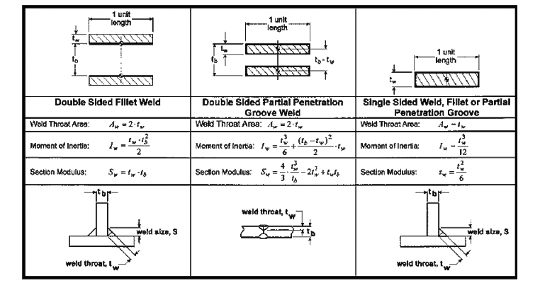
Weld Geometry and Size
The weld geometry and size can significantly impact the shear strength of a weld. A larger weld area and throat thickness can increase the shear strength, but may also increase the residual stresses and distortion. The weld shape and orientation can also affect the shear strength, with transverse welds generally being stronger than longitudinal welds.
- Determine the weld area and throat thickness
- Consider the weld shape and orientation
- Calculate the weld size and geometry using mathematical models or finite element analysis
Testing and Inspection Methods
Testing and inspection methods are used to determine the shear strength of a weld. Destructive testing methods, such as tensile testing and shear testing, can provide accurate results, but may damage the weld. Non-destructive testing methods, such as ultrasonic testing and radiography, can provide rapid and reliable results without damaging the weld.
- Select the testing method based on the weld type and material properties
- Consider the inspection method used to evaluate the weld quality
- Interpret the test results using standardized procedures and mathematical models
Calculating Shear Strength using Mathematical Models
Mathematical models can be used to calculate the shear strength of a weld based on the weld geometry, material properties, and loading conditions. Finite element analysis and numerical methods can provide accurate results, but require specialized software and expertise. Simplified models, such as the shear strength formula, can provide rapid and reliable results, but may not account for complex loading conditions.
- Select the mathematical model based on the weld type and complexity
- Consider the loading conditions, such as tension, compression, and torsion
- Calculate the shear strength using standardized procedures and software tools
What is the torsional stress of a solid shaft?
The torsional stress of a solid shaft is a measure of the twisting force that causes the shaft to deform. It is an important parameter in the design and analysis of mechanical systems, as it can affect the stability and reliability of the system. The torsional stress is typically calculated using the torque and polar moment of inertia of the shaft.
Calculating Torsional Stress
Calculating the torsional stress of a solid shaft involves using the formula: τ = T r / J, where τ is the torsional stress, T is the torque, r is the radius of the shaft, and J is the polar moment of inertia. The polar moment of inertia is a measure of the shaft's resistance to torsion. Some key factors to consider when calculating torsional stress are:
- The material properties of the shaft, such as its modulus of elasticity and yield strength
- The geometry of the shaft, including its length and diameter
- The loading conditions, including the torque and axial load applied to the shaft
Factors Affecting Torsional Stress
Several factors can affect the torsional stress of a solid shaft, including the material properties, geometry, and loading conditions. The material properties can affect the shaft's resistance to torsion, while the geometry can affect the shaft's polar moment of inertia. The loading conditions can also affect the torsional stress, as the torque and axial load can cause the shaft to deform. Some key factors to consider are:
- The type of material used for the shaft, such as steel or aluminum
- The size and shape of the shaft, including its length and diameter
- The loading conditions, including the torque and axial load applied to the shaft
Importance of Torsional Stress
The torsional stress of a solid shaft is an important parameter in the design and analysis of mechanical systems. High torsional stress can cause the shaft to fail, leading to system downtime and maintenance costs. Therefore, it is essential to consider the torsional stress when designing and analyzing mechanical systems. Some key areas where torsional stress is important include:
- Gearboxes and transmissions, where the torsional stress can affect the gear teeth and bearings
- Pumps and turbines, where the torsional stress can affect the impeller and shaft
- Aerospace and automotive applications, where the torsional stress can affect the system reliability and safety
Torsional Stress Analysis
Torsional stress analysis is a critical step in the design and analysis of mechanical systems. It involves using mathematical models and computer simulations to calculate the torsional stress of a solid shaft. The analysis can help engineers to identify potential problems and optimize the design of the system. Some key tools used in torsional stress analysis include:
- Finite element analysis (FEA) software, such as ANSYS or ABAQUS
- Computer-aided design (CAD) software, such as SolidWorks or CATIA
- Matlab or Python programming languages, which can be used to develop custom models and simulations
Designing for Torsional Stress
Designing for torsional stress involves using engineering principles and material properties to minimize the torsional stress of a solid shaft. It requires careful consideration of the loading conditions, geometry, and material properties. Some key strategies for designing for torsional stress include:
- Using a strong and stiff material, such as steel or titanium
- Optimizing the geometry of the shaft, including its length and diameter
- Using stress-reducing features, such as fillets or chamfers, to minimize the stress concentrations
Frequently Asked Questions (FAQs)
What is the purpose of the Weld Shear Stress for Applied Torque on Solid Shaft Calculator?
The Weld Shear Stress for Applied Torque on Solid Shaft Calculator is a tool designed to calculate the shear stress that occurs in a solid shaft when a torque is applied to it. This calculator is particularly useful in engineering and mechanical design applications, where it is essential to determine the stress and strain on a shaft due to torsional loads. By using this calculator, engineers and designers can ensure that their shaft designs are safe and reliable, and that they can withstand the applied torques without failing. The calculator takes into account the material properties of the shaft, such as its yield strength and ultimate strength, as well as the geometric parameters of the shaft, such as its diameter and length.
How does the Weld Shear Stress for Applied Torque on Solid Shaft Calculator work?
The Weld Shear Stress for Applied Torque on Solid Shaft Calculator works by using a mathematical formula to calculate the shear stress in the shaft. The formula takes into account the applied torque, the polar moment of inertia of the shaft, and the distance from the neutral axis to the point where the shear stress is being calculated. The calculator also allows users to input the material properties of the shaft, such as its yield strength and ultimate strength, which are used to determine the allowable shear stress. The calculator then compares the calculated shear stress to the allowable shear stress to determine whether the shaft design is safe or not. The calculator uses -unit conversions to ensure that the inputs and outputs are in the correct units, such as pounds or newtons for torque, and inches or millimeters for length.
What are the limitations of the Weld Shear Stress for Applied Torque on Solid Shaft Calculator?
The Weld Shear Stress for Applied Torque on Solid Shaft Calculator has several limitations that users should be aware of. One of the main limitations is that it assumes a solid shaft with a circular cross-section, and does not account for hollow shafts or shafts with non-circular cross-sections. Additionally, the calculator assumes that the applied torque is steady-state, and does not account for dynamic or transient loads. The calculator also assumes that the material properties of the shaft are isotropic, and does not account for anisotropic materials. Furthermore, the calculator does not account for other types of loads that may be applied to the shaft, such as axial loads or bending loads. Users should be aware of these limitations and use the calculator accordingly, and should consult other sources or experts if they have any doubts or uncertainties.
How can I use the Weld Shear Stress for Applied Torque on Solid Shaft Calculator in my design process?
The Weld Shear Stress for Applied Torque on Solid Shaft Calculator can be a valuable tool in the design process of a solid shaft. By using the calculator, designers and engineers can quickly and easily determine the shear stress that occurs in the shaft due to applied torques, and can use this information to optimize their shaft design. The calculator can be used to iterate on different design parameters, such as the diameter and length of the shaft, to find the optimal design that meets the required specifications. The calculator can also be used to compare different material options, and to determine the most cost-effective solution. Additionally, the calculator can be used to validate the design of the shaft, and to ensure that it meets the required safety factors and regulatory requirements. By using the calculator in conjunction with other design tools and techniques, designers and engineers can create safe, reliable, and efficient shaft designs that meet the required specifications.
Deja una respuesta
Entradas Relacionadas