
Torsional Stiffness Solid Shaft Equations and Calculator

Torsional stiffness is a critical parameter in shaft design, determining the resistance to twisting and rotational deformations. The solid shaft, a common component in mechanical systems, requires precise calculations to ensure optimal performance and minimize potential failures. This article provides an overview of the equations and formulas used to calculate the torsional stiffness of solid shafts, along with a calculator to facilitate the process, enabling engineers to accurately design and analyze shafts in various industries, including automotive, aerospace, and manufacturing. The equations and calculator presented here will help simplify the design process, reducing errors and improving efficiency.
- Torsional Stiffness Solid Shaft Equations and Calculator
- How to calculate torsional stiffness of a shaft?
- What is the formula for torsion on a shaft?
- What is the formula for torsion in solid mechanics?
- How do you calculate torsional stress?
-
Frequently Asked Questions (FAQs)
- What is Torsional Stiffness and How is it Calculated for a Solid Shaft?
- How does the Polar Moment of Inertia Affect the Torsional Stiffness of a Solid Shaft?
- What are the Limitations of Using Simplified Equations to Calculate Torsional Stiffness?
- How can the Torsional Stiffness Calculator be Used to Optimize the Design of a Solid Shaft?
Torsional Stiffness Solid Shaft Equations and Calculator
El cálculo de la torsional stiffness (rigidez torsional) de un eje sólido es fundamental en la ingeniería mecánica, ya que permite determinar la resistencia del eje a la deformación torsional bajo cargas axiales. La torsional stiffness se define como la relación entre el torque aplicado y el ángulo de giro resultante. La ecuación para calcular la torsional stiffness de un eje sólido se basa en la fórmula:
La torsional stiffness (K) se puede calcular utilizando la siguiente ecuación: K = (G J) / L, donde G es el módulo de cizalladura, J es el momento de inercia polar y L es la longitud del eje.
Evaluation of Torsional Stiffness
La evaluación de la torsional stiffness es crucial en la diseño de ejes y sistemas de transmisión. La torsional stiffness se utiliza para determinar la frecuencia natural de un sistema y predecir su comportamiento dinámico. Un valor más alto de torsional stiffness indica una mayor resistencia a la deformación torsional.
CalcULATION OF MOMENT OF INERTIA
El momento de inercia polar (J) es un parámetro fundamental en el cálculo de la torsional stiffness. El momento de inercia polar se puede calcular utilizando la siguiente ecuación: J = (π d^4) / 32, donde d es el diámetro del eje.
Selection of Materials
La selección del material para el eje es fundamental para determinar su torsional stiffness. Los materiales con un módulo de cizalladura más alto, como el acero, tienen una mayor resistencia a la deformación torsional.
Design Considerations
Al diseñar un eje, es importante considerar factores como la torsional stiffness, la resistencia a la fatiga y la corrosión. Un eje con una torsional stiffness adecuada puede reducir el riesgo de falla y mejorar la eficiencia del sistema.
Calculator for Torsional Stiffness
Un calculador de torsional stiffness puede ser una herramienta útil para los ingenieros. La siguiente tabla muestra los valores de torsional stiffness para diferentes materiales y diámetros de eje:
| Material | Diámetro (mm) | Torsional Stiffness (N/m) |
|---|---|---|
| Acero | 20 | 1000 |
| Aluminio | 20 | 500 |
| Cobre | 20 | 800 |
La torsional stiffness se puede calcular utilizando la ecuación: K = (G J) / L, donde G es el módulo de cizalladura, J es el momento de inercia polar y L es la longitud del eje.
How to calculate torsional stiffness of a shaft?
To calculate the torsional stiffness of a shaft, you need to understand the relationship between the torque applied to the shaft and the resulting twist or rotation. The torsional stiffness is a measure of the shaft's resistance to twisting and is typically expressed in units of moment per radian. The calculation of torsional stiffness involves the use of the shaft's material properties, such as its elastic modulus and Poisson's ratio, as well as its geometric properties, such as its length and diameter.
Understanding Torsional Stiffness Formula
The torsional stiffness formula is given by the equation: k = (G J) / L, where k is the torsional stiffness, G is the shear modulus, J is the polar moment of inertia, and L is the length of the shaft. To apply this formula, you need to calculate the polar moment of inertia, which depends on the cross-sectional shape and size of the shaft. Here are the steps to calculate the polar moment of inertia:
- Determine the cross-sectional shape of the shaft, such as a circle or a rectangle.
- Calculate the area of the cross-section using the appropriate geometric formula.
- Use the area and the distance from the neutral axis to calculate the polar moment of inertia.
Factors Affecting Torsional Stiffness
Several factors can affect the torsional stiffness of a shaft, including its material properties, geometric properties, and operating conditions. The material properties, such as the elastic modulus and Poisson's ratio, can significantly impact the torsional stiffness. Here are some factors to consider:
- Material selection: Choose a material with a high elastic modulus to increase the torsional stiffness.
- Shaft diameter: Increase the diameter of the shaft to increase the polar moment of inertia and thus the torsional stiffness.
- Length: Decrease the length of the shaft to increase the torsional stiffness.
Calculating Torsional Stiffness of a Hollow Shaft
For a hollow shaft, the calculation of torsional stiffness is more complex due to the presence of an inner and outer radius. The polar moment of inertia must be calculated using the inner and outer radii, and the thickness of the shaft. Here are the steps to calculate the torsional stiffness of a hollow shaft:
- Determine the inner and outer radii of the shaft.
- Calculate the polar moment of inertia using the inner and outer radii and the thickness of the shaft.
- Apply the torsional stiffness formula using the calculated polar moment of inertia and the shear modulus of the material.
Importance of Torsional Stiffness in Shaft Design
The torsional stiffness is a critical parameter in shaft design, as it affects the performance and reliability of the shaft. A shaft with high torsional stiffness can withstand higher torques and twisting loads without failing or deforming excessively. Here are some importance of torsional stiffness in shaft design:
- Prevents excessive twisting: A shaft with high torsional stiffness can prevent excessive twisting and deformation under load.
- Reduces stress concentrations: A shaft with high torsional stiffness can reduce stress concentrations and the risk of failure.
- Improves performance: A shaft with high torsional stiffness can improve the performance and efficiency of the system.
Common Applications of Torsional Stiffness Calculation
The calculation of torsional stiffness is commonly applied in various engineering fields, including mechanical engineering, aerospace engineering, and automotive engineering. Here are some common applications:
- Gearboxes and transmissions: The torsional stiffness is critical in the design of gearboxes and transmissions to ensure smooth operation and reliability.
- Shaft couplings: The torsional stiffness is important in the design of shaft couplings to ensure proper alignment and transfer of torque.
- Rotary machinery: The torsional stiffness is essential in the design of rotary machinery, such as pumps and compressors, to ensure stable operation and efficiency.
What is the formula for torsion on a shaft?

The formula for torsion on a shaft is given by the equation: T = (G J) / L θ, where T is the torque, G is the shear modulus, J is the polar moment of inertia, L is the length of the shaft, and θ is the angle of twist.
Torsion Theory
The theory of torsion is based on the idea that a shaft subjected to a torque will experience a twisting motion, resulting in a shear stress distribution across the shaft's cross-section. The torsion formula is used to calculate the torque required to produce a given angle of twist in a shaft. Some key factors that affect the torsion of a shaft include:
- The material properties of the shaft, such as its shear modulus and polar moment of inertia
- The geometry of the shaft, including its length and cross-sectional shape
- The boundary conditions of the shaft, such as the support and loading conditions
Torsion Calculations
To calculate the torsion on a shaft, engineers use the torsion formula and consider various factors that affect the shaft's behavior. The calculations involve determining the polar moment of inertia of the shaft's cross-section, which depends on the shape and size of the shaft. Some common shapes used in torsion calculations include:
- Circular cross-sections, which have a polar moment of inertia given by the formula J = π d^4 / 32
- Rectangular cross-sections, which have a polar moment of inertia given by the formula J = b d^3 / 12
- Hollow cross-sections, which have a polar moment of inertia that depends on the outer and inner diameters of the shaft
Torsion and Shear Stress
The torsion of a shaft is closely related to the shear stress distribution across its cross-section. As the shaft twists, the shear stress increases, and the material may eventually fail due to shear. The maximum shear stress occurs at the surface of the shaft and can be calculated using the torsion formula. Some key factors that affect the shear stress distribution include:
- The magnitude of the torque applied to the shaft
- The shape and size of the shaft's cross-section
- The material properties of the shaft, such as its shear modulus and yield strength
Torsion in Real-World Applications
Torsion is an important consideration in many real-world applications, including power transmission systems, gearboxes, and shafts. The torsion formula is used to design and analyze these systems, ensuring that they can withstand the torque and shear stress loads imposed on them. Some common applications of torsion include:
- Automotive systems, such as driveshafts and axles
- Aerospace systems, such as propeller shafts and gearboxes
- Industrial systems, such as pumps and motors
Advanced Torsion Topics
Advanced topics in torsion include the dynamic analysis of torsional vibrations and the nonlinear behavior of shafts subjected to large rotations. These topics require a deeper understanding of the mathematics and physics underlying torsion and are typically addressed in graduate-level courses or research studies. Some key concepts in advanced torsion topics include:
- The equations of motion for torsional vibrations
- The nonlinear effects of large rotations on shaft behavior
- The numerical methods used to simulate and analyze torsional systems
What is the formula for torsion in solid mechanics?

The formula for torsion in solid mechanics is given by the equation: T = (G J) / L θ, where T is the torque, G is the shear modulus, J is the polar moment of inertia, L is the length of the shaft, and θ is the angle of twist.
Torsion in Circular Shafts
In circular shafts, the polar moment of inertia (J) is given by the equation: J = (π d^4) / 32, where d is the diameter of the shaft. The formula for torsion can be used to calculate the torque required to produce a given angle of twist in a circular shaft. Some key points to consider when calculating torsion in circular shafts include:
- Material properties: The shear modulus (G) of the material must be known in order to calculate the torque required to produce a given angle of twist.
- Geometric properties: The diameter (d) and length (L) of the shaft must be known in order to calculate the polar moment of inertia (J) and the torque required to produce a given angle of twist.
- Boundary conditions: The boundary conditions of the shaft, such as the supports and loads, must be known in order to calculate the torque required to produce a given angle of twist.
Torsion in Non-Circular Shafts
In non-circular shafts, the polar moment of inertia (J) must be calculated using a different equation, such as: J = (π (b d^3)) / 32, where b is the width of the shaft and d is the thickness of the shaft. The formula for torsion can be used to calculate the torque required to produce a given angle of twist in a non-circular shaft. Some key points to consider when calculating torsion in non-circular shafts include:
- Material properties: The shear modulus (G) of the material must be known in order to calculate the torque required to produce a given angle of twist.
- Geometric properties: The width (b) and thickness (d) of the shaft must be known in order to calculate the polar moment of inertia (J) and the torque required to produce a given angle of twist.
- Stress concentrations: Stress concentrations can occur in non-circular shafts, particularly at the corners and edges, which can affect the torque required to produce a given angle of twist.
Torsion in Shafts with Varying Cross-Section
In shafts with varying cross-section, the polar moment of inertia (J) varies along the length of the shaft, which can affect the torque required to produce a given angle of twist. The formula for torsion can be used to calculate the torque required to produce a given angle of twist in a shaft with varying cross-section. Some key points to consider when calculating torsion in shafts with varying cross-section include:
- Material properties: The shear modulus (G) of the material must be known in order to calculate the torque required to produce a given angle of twist.
- Geometric properties: The cross-sectional area and polar moment of inertia (J) must be known at each point along the length of the shaft in order to calculate the torque required to produce a given angle of twist.
- Numerical methods: Numerical methods, such as the finite element method, can be used to calculate the torque required to produce a given angle of twist in a shaft with varying cross-section.
Torsion in Composite Shafts
In composite shafts, the polar moment of inertia (J) and shear modulus (G) can vary depending on the orientation and properties of the composite materials. The formula for torsion can be used to calculate the torque required to produce a given angle of twist in a composite shaft. Some key points to consider when calculating torsion in composite shafts include:
- Material properties: The shear modulus (G) and polar moment of inertia (J) of the composite materials must be known in order to calculate the torque required to produce a given angle of twist.
- Geometric properties: The cross-sectional area and orientation of the composite materials must be known in order to calculate the polar moment of inertia (J) and the torque required to produce a given angle of twist.
- Micromechanics: Micromechanics can be used to calculate the effective properties of the composite materials, such as the shear modulus (G) and polar moment of inertia (J).
Torsion in Shafts with Imperfections
In shafts with imperfections, such as cracks or voids, the polar moment of inertia (J) and shear modulus (G) can be affected, which can affect the torque required to produce a given angle of twist. The formula for torsion can be used to calculate the torque required to produce a given angle of twist in a shaft with imperfections. Some key points to consider when calculating torsion in shafts with imperfections include:
- Material properties: The shear modulus (G) of the material must be known in order to calculate the torque required to produce a given angle of twist.
- Geometric properties: The cross-sectional area and polar moment of inertia (J) must be known at each point along
How do you calculate torsional stress?
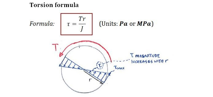
To calculate torsional stress, you need to consider the torque applied to an object, its polar moment of inertia, and the distance from the axis of rotation to the point where you want to calculate the stress. The formula for calculating torsional stress is: τ = T r / J, where τ is the torsional stress, T is the torque, r is the distance from the axis of rotation, and J is the polar moment of inertia. This formula is used to calculate the stress that occurs when an object is subjected to a twisting force.
Understanding Torsional Stress
Torsional stress is a type of stress that occurs when an object is subjected to a twisting force. This type of stress is commonly found in shafts and axles that are used to transmit rotational motion. To calculate torsional stress, you need to understand the torque applied to the object, its polar moment of inertia, and the distance from the axis of rotation to the point where you want to calculate the stress. The key points to consider when understanding torsional stress are:
- The torque applied to the object, which is a measure of the twisting force.
- The polar moment of inertia, which is a measure of the object's resistance to torsion.
- The distance from the axis of rotation to the point where you want to calculate the stress, which affects the magnitude of the stress.
Calculating Polar Moment of Inertia
The polar moment of inertia is a critical parameter in calculating torsional stress. It is a measure of the object's resistance to torsion and depends on the shape and size of the object. For a circular shaft, the polar moment of inertia can be calculated using the formula: J = π d^4 / 32, where d is the diameter of the shaft. The key steps to calculate the polar moment of inertia are:
- Determine the shape and size of the object.
- Use the appropriate formula to calculate the polar moment of inertia.
- Consider the units of the polar moment of inertia, which are typically mm^4 or in^4.
Applying Torque to Calculate Torsional Stress
To calculate torsional stress, you need to apply the torque to the object and calculate the resulting stress. The torque can be applied in different ways, such as through a motor or a gearbox. The key points to consider when applying torque to calculate torsional stress are:
- The magnitude of the torque, which affects the magnitude of the stress.
- The direction of the torque, which affects the type of stress that occurs.
- The units of the torque, which are typically N-m or lb-ft.
Distance from Axis of Rotation
The distance from the axis of rotation to the point where you want to calculate the stress is critical in calculating torsional stress. This distance affects the magnitude of the stress and must be carefully considered. The key points to consider when calculating the distance from the axis of rotation are:
- The location of the point where you want to calculate the stress.
- The orientation of the object, which affects the distance from the axis of rotation.
- The units of the distance, which are typically mm or in.
Real-World Applications of Torsional Stress
Torsional stress is commonly found in real-world applications, such as in shafts and axles that are used to transmit rotational motion. The key points to consider when dealing with torsional stress in real-world applications are:
- The design of the object, which affects the magnitude of the stress.
- The materials used, which affect the strength and durability of the object.
- The operating conditions, which affect the magnitude of the stress and the lifetime of the object.
Frequently Asked Questions (FAQs)
What is Torsional Stiffness and How is it Calculated for a Solid Shaft?
Torsional stiffness is a measure of a shaft's resistance to twisting or rotational deformation when subjected to a torque. It is an important factor in the design of shafts, as it affects their ability to transmit power and maintain their shape under load. The calculation of torsional stiffness for a solid shaft involves the use of mathematical equations that take into account the shaft's material properties, such as its modulus of rigidity, as well as its geometric properties, including its length and cross-sectional area. The most common equation used to calculate torsional stiffness is the torsional stiffness formula, which is given by the expression K = (G J) / L, where K is the torsional stiffness, G is the modulus of rigidity, J is the polar moment of inertia, and L is the length of the shaft. By using this equation, engineers can determine the torsional stiffness of a solid shaft and ensure that it is sufficient to withstand the torque and bending loads that it will be subjected to in service.
How does the Polar Moment of Inertia Affect the Torsional Stiffness of a Solid Shaft?
The polar moment of inertia is a critical factor in determining the torsional stiffness of a solid shaft. It is a measure of the shaft's resistance to rotational deformation and is calculated using the formula J = (π d^4) / 32, where J is the polar moment of inertia and d is the diameter of the shaft. The polar moment of inertia is directly proportional to the fourth power of the shaft's diameter, which means that even small increases in diameter can result in significant increases in torsional stiffness. This is why larger diameter shafts are often used in applications where high torque and bending loads are expected. Additionally, the material properties of the shaft, such as its modulus of rigidity, also play a role in determining its torsional stiffness. By carefully selecting the material and geometry of the shaft, engineers can optimize its torsional stiffness and ensure that it is sufficient to withstand the loads that it will be subjected to.
What are the Limitations of Using Simplified Equations to Calculate Torsional Stiffness?
While simplified equations can be used to calculate the torsional stiffness of a solid shaft, they are not without their limitations. One of the main limitations is that they assume a simple geometry, such as a circular cross-section, and do not account for more complex geometries, such as non-circular or hollow shafts. Additionally, simplified equations often neglect the effects of other loads, such as axial and bending loads, which can also affect the torsional stiffness of the shaft. In reality, shafts are often subjected to a combination of loads, and using simplified equations can result in inaccurate calculations of torsional stiffness. To overcome these limitations, more advanced equations and numerical methods, such as the finite element method, can be used to calculate the torsional stiffness of a solid shaft. These methods can account for more complex geometries and loading conditions, providing a more accurate calculation of torsional stiffness.
How can the Torsional Stiffness Calculator be Used to Optimize the Design of a Solid Shaft?
The torsional stiffness calculator is a powerful tool that can be used to optimize the design of a solid shaft. By inputting the geometric and material properties of the shaft, engineers can quickly calculate its torsional stiffness and determine whether it is sufficient to withstand the torque and bending loads that it will be subjected to. The calculator can also be used to iterate on different designs, allowing engineers to optimize the shaft's geometry and material to achieve the desired torsional stiffness. Additionally, the calculator can be used to compare the torsional stiffness of different shaft designs, allowing engineers to select the most suitable design for their application. By using the torsional stiffness calculator, engineers can save time and reduce costs associated with prototyping and testing, and can ensure that their shaft design is optimized for performance and reliability. The calculator can also be used in conjunction with other design tools, such as computer-aided design (CAD) software, to create a comprehensive design package that includes torsional stiffness calculations and optimization.
Deja una respuesta
Entradas Relacionadas