
Strain Gage Transducer Half Bridge Calculator and Equation

The Strain Gage Transducer Half Bridge Calculator is a valuable tool for engineers and researchers working with strain gage transducers. Strain gages are widely used to measure mechanical strain, pressure, and force in various applications. The half bridge configuration is a common setup for strain gage transducers, offering a balance between sensitivity and simplicity. This article provides an overview of the Strain Gage Transducer Half Bridge Calculator and Equation, including its underlying principles, calculation methods, and practical applications, helping users to accurately measure and interpret strain data. Accurate calculations are crucial for reliable results.
-
Understanding the Strain Gage Transducer Half Bridge Calculator and Equation
- What is a Strain Gage Transducer Half Bridge?
- How Does the Half Bridge Calculator Work?
- What is the Equation for the Strain Gage Transducer Half Bridge?
- Applications of the Strain Gage Transducer Half Bridge Calculator and Equation
- Advantages of Using the Strain Gage Transducer Half Bridge Calculator and Equation
- What is the formula for the strain gauge half-bridge?
- What is the equation for the strain gauge?
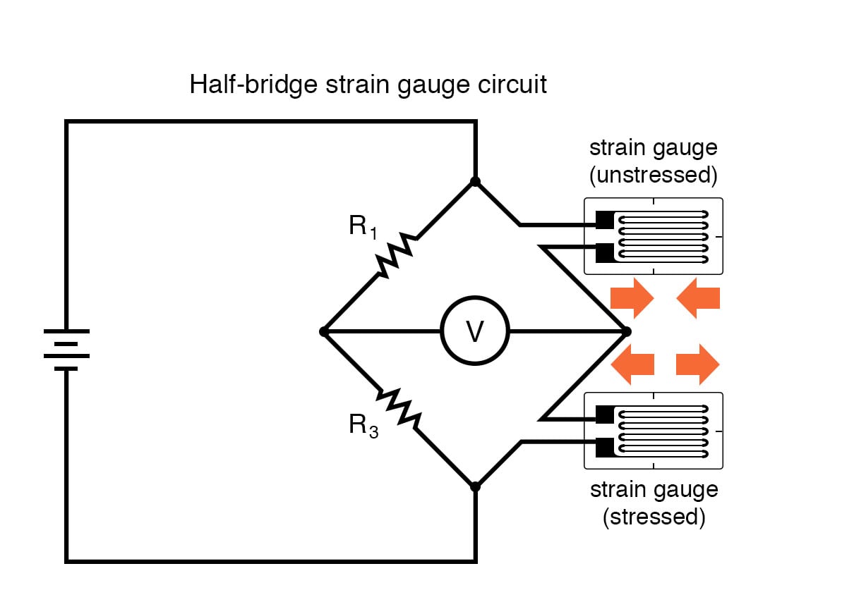
- What is the configuration of a half-bridge strain gauge?
- What is the bridge factor of a strain gauge?
-
Frequently Asked Questions (FAQs)
- What is a Strain Gage Transducer Half Bridge Calculator and Equation?
- How does the Strain Gage Transducer Half Bridge Calculator and Equation work?
- What are the advantages of using a Strain Gage Transducer Half Bridge Calculator and Equation?
- What are the common applications of a Strain Gage Transducer Half Bridge Calculator and Equation?
Understanding the Strain Gage Transducer Half Bridge Calculator and Equation
The Strain Gage Transducer Half Bridge Calculator and Equation are essential tools used in the field of engineering to measure strain and stress on materials. A strain gage is a sensor that measures the deformation of an object under stress, and the half bridge configuration is a common setup used to amplify the signal from the gage. The calculator and equation are used to determine the output voltage of the half bridge circuit, which is proportional to the strain measured by the gage.
What is a Strain Gage Transducer Half Bridge?
A Strain Gage Transducer Half Bridge is a type of transducer that uses a strain gage to measure the deformation of an object under stress. The half bridge configuration consists of two resistors, one of which is the strain gage, connected in a Wheatstone bridge circuit. The strain gage is bonded to the material being measured, and as the material deforms, the strain gage changes its resistance, causing a change in the output voltage of the circuit.
How Does the Half Bridge Calculator Work?
The Half Bridge Calculator is a tool used to determine the output voltage of the half bridge circuit. It takes into account the gain of the amplifier, the excitation voltage, and the sensitivity of the strain gage. The calculator uses the following equation to calculate the output voltage: Vout = (Vex G (Rg / R)) / (2 R), where Vex is the excitation voltage, G is the gain of the amplifier, Rg is the resistance of the strain gage, and R is the resistance of the other resistor in the circuit.
What is the Equation for the Strain Gage Transducer Half Bridge?
The equation for the Strain Gage Transducer Half Bridge is: Vout = (Vex G (Rg / R)) / (2 R), where Vout is the output voltage, Vex is the excitation voltage, G is the gain of the amplifier, Rg is the resistance of the strain gage, and R is the resistance of the other resistor in the circuit. This equation can be used to calculate the output voltage of the half bridge circuit, given the gain of the amplifier, the excitation voltage, and the sensitivity of the strain gage.
Applications of the Strain Gage Transducer Half Bridge Calculator and Equation
The Strain Gage Transducer Half Bridge Calculator and Equation have a wide range of applications in the field of engineering, including stress analysis, material testing, and vibration measurement. They are used in various industries, such as aerospace, automotive, and civil engineering, to measure the strain and stress on materials and structures.
Advantages of Using the Strain Gage Transducer Half Bridge Calculator and Equation
The Strain Gage Transducer Half Bridge Calculator and Equation offer several advantages, including high accuracy, low noise, and easy calibration. They are also cost-effective and easy to use, making them a popular choice among engineers and researchers. The following table summarizes the advantages of using the Strain Gage Transducer Half Bridge Calculator and Equation:
| Advantage | Description |
|---|---|
| High Accuracy | The calculator and equation provide high accuracy measurements of strain and stress. |
| Low Noise | The half bridge circuit is less susceptible to noise and interference. |
| Easy Calibration | The calculator and equation make it easy to calibrate the strain gage and amplifier. |
| Cost-Effective | The calculator and equation are cost-effective and easy to use. |
| Easy to Use | The calculator and equation are easy to use and require minimal training. |
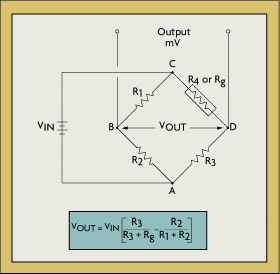
What is the formula for the strain gauge half-bridge?
The formula for the strain gauge half-bridge is a critical concept in the field of mechanical engineering and electronics. The half-bridge configuration is commonly used to measure strain and stress in various applications, including weight measurement, force measurement, and torque measurement. The formula for the half-bridge is given by: Vout = (R2 - R1) / (R2 + R1) Vin, where Vout is the output voltage, R1 and R2 are the resistances of the two strain gauges, and Vin is the input voltage.
Principle of Strain Gauge Half-Bridge
The strain gauge half-bridge is based on the principle of resistance change in response to mechanical strain. When a strain gauge is subjected to tension or compression, its resistance changes, causing a corresponding change in the output voltage. The half-bridge configuration allows for the measurement of this change in resistance, which is directly proportional to the strain. The key benefits of the half-bridge configuration include:
- High sensitivity: The half-bridge configuration provides high sensitivity to strain changes.
- Low noise: The half-bridge configuration is less prone to noise and interference.
- Simple implementation: The half-bridge configuration is relatively simple to implement and requires minimal electronic components.
Applications of Strain Gauge Half-Bridge
The strain gauge half-bridge has a wide range of applications in various fields, including aerospace, automotive, and industrial automation. Some of the most common applications include:
- Weight measurement: The half-bridge configuration is used in weight measurement applications, such as scales and load cells.
- Force measurement: The half-bridge configuration is used in force measurement applications, such as force sensors and pressure sensors.
- Torque measurement: The half-bridge configuration is used in torque measurement applications, such as torque sensors and rotary encoders.
Advantages of Strain Gauge Half-Bridge
The strain gauge half-bridge has several advantages over other strain measurement techniques, including:
- High accuracy: The half-bridge configuration provides high accuracy and repeatability.
- Low cost: The half-bridge configuration is relatively low-cost compared to other strain measurement techniques.
- Easy implementation: The half-bridge configuration is relatively simple to implement and requires minimal electronic components.
Limitations of Strain Gauge Half-Bridge
The strain gauge half-bridge has several limitations, including:
- Sensitivity to temperature: The half-bridge configuration is sensitive to temperature changes, which can affect accuracy.
- Non-linearity: The half-bridge configuration can exhibit non-linearity in response to large strains.
- Hysteresis: The half-bridge configuration can exhibit hysteresis in response to repeated loading and unloading.
Future Developments in Strain Gauge Half-Bridge
The strain gauge half-bridge is a well-established technology, but there are ongoing research and development efforts to improve its performance and capabilities. Some of the future developments include:
- New materials: Researchers are exploring new materials and technologies to improve the sensitivity and accuracy of strain gauges.
- Advanced signal processing: Researchers are developing advanced signal processing techniques to improve the noise immunity and accuracy of strain gauge half-bridge systems.
- Integration with other sensors: Researchers are exploring the integration of strain gauge half-bridge systems with other sensors and technologies to enable multi-parameter measurement and condition monitoring.
What is the equation for the strain gauge?

The equation for the strain gauge is a fundamental concept in the field of mechanical engineering and materials science. It is used to measure the strain or deformation of an object under stress. The equation is based on the principle of piezoresistance, which states that the resistance of a material changes when it is subjected to stress or strain. The equation for the strain gauge is given by: ΔR/R = GF ε, where ΔR is the change in resistance, R is the original resistance, GF is the gauge factor, and ε is the strain.
Introduction to Strain Gauges
The strain gauge is a type of sensor that is used to measure the strain or deformation of an object. It consists of a metal foil or semiconductor material that is attached to the object being measured. When the object is subjected to stress or strain, the resistance of the strain gauge changes, allowing the strain! to be calculated. The strain gauge is a widely used sensor in many fields, including mechanical engineering, 材料 science, and civil engineering. Some of the key features of strain gauges include:
- High sensitivity: Strain gauges are highly sensitive to changes in strain, allowing for accurate measurements.
- Low power consumption: Strain gauges typically require low power to operate, making them suitable for use in battery-powered devices.
- Compact size: Strain gauges are often small and compact, making them easy to integrate into complex systems.
Working Principle of Strain Gauges
The working principle of strain gauges is based on the concept of piezoresistance, which states that the resistance of a material changes when it is subjected to stress or strain. When a strain gauge is attached to an object, it experiences the same strain as the object. The resistance of the strain gauge changes in response to the strain, allowing the strain to be calculated. The gauge factor is a measure of the sensitivity of the strain gauge to strain. Some of the key factors that affect the working principle of strain gauges include:
- Material properties: The material properties of the strain gauge, such as its resistance and gauge factor, affect its sensitivity and accuracy.
- Temperature effects: Temperature changes can affect the resistance of the strain gauge, leading to errors in strain measurements.
- Humidity effects: Humidity can also affect the resistance of the strain gauge, particularly in high-humidity environments.
Types of Strain Gauges
There are several types of strain gauges available, each with its own unique characteristics and applications. Some of the most common types of strain gauges include:
- Metal foil strain gauges: These are the most common type of strain gauge and are made from a metal foil material.
- Semiconductor strain gauges: These strain gauges are made from semiconductor materials and offer higher sensitivity and accuracy than metal foil strain gauges.
- Optical strain gauges: These strain gauges use optical fibers to measure strain and offer high accuracy and resolution.
Applications of Strain Gauges
Strain gauges have a wide range of applications in many fields, including mechanical engineering, materials science, and civil engineering. Some of the most common applications of strain gauges include:
- Structural health monitoring: Strain gauges are used to monitor the health of structures, such as bridges and buildings.
- Machine condition monitoring: Strain gauges are used to monitor the condition of machines, such as engines and gearboxes.
- Biomechanical measurements: Strain gauges are used to measure biomechanical parameters, such as muscle activity and joint movement.
Calibration and Validation of Strain Gauges
Calibration and validation of strain gauges are critical steps in ensuring the accuracy and reliability of strain measurements. Calibration involves adjusting the strain gauge to produce a known output in response to a known input. Validation involves verifying the accuracy of the strain gauge by comparing its output to a known reference. Some of the key factors that affect the calibration and validation of strain gauges include:
- Temperature effects: Temperature changes can affect the calibration and validation of strain gauges.
- Humidity effects: Humidity can also affect the calibration and validation of strain gauges.
- Material properties: The material properties of the strain gauge, such as its resistance and gauge factor, affect its calibration and validation.
What is the configuration of a half-bridge strain gauge?
The configuration of a half-bridge strain gauge is a type of strain gauge configuration where two gauges are connected in a bridge circuit, with one gauge measuring the strain and the other gauge serving as a dummy gauge. This configuration is commonly used in transducer applications where a strain measurement is required.
Half-Bridge Configuration Advantages
The half-bridge configuration offers several advantages, including improved accuracy and increased sensitivity. This is because the dummy gauge helps to compensate for any temperature changes that may affect the measurement. The configuration also allows for easier calibration and reduced noise. Some of the key benefits of the half-bridge configuration include:
- Improved accuracy: The half-bridge configuration provides more accurate measurements due to the compensation provided by the dummy gauge.
- Increased sensitivity: The configuration allows for increased sensitivity to strain measurements, making it suitable for applications where high precision is required.
- Easier calibration: The half-bridge configuration makes it easier to calibrate the strain gauge, as the dummy gauge provides a reference point.
Half-Bridge Configuration Applications
The half-bridge configuration is commonly used in a variety of applications, including transducer applications, weight measurement systems, and stress analysis. This is because the configuration provides high accuracy and reliability, making it suitable for critical applications. Some examples of half-bridge configuration applications include:
- Transducer applications: The half-bridge configuration is used in transducer applications where a strain measurement is required, such as in pressure sensors and load cells.
- Weight measurement systems: The configuration is used in weight measurement systems, such as scales and balance systems.
- Stress analysis: The half-bridge configuration is used in stress analysis applications, such as in fatigue testing and material testing.
Half-Bridge Configuration Components
The half-bridge configuration consists of several components, including the strain gauge, dummy gauge, and bridge circuit. The strain gauge is the sensitive element that measures the strain, while the dummy gauge serves as a reference point. The bridge circuit is used to amplify and condition the signal. Some of the key components of the half-bridge configuration include:
- Strain gauge: The strain gauge is the sensitive element that measures the strain.
- Dummy gauge: The dummy gauge serves as a reference point and helps to compensate for any temperature changes.
- Bridge circuit: The bridge circuit is used to amplify and condition the signal from the strain gauge.
Half-Bridge Configuration Limitations
The half-bridge configuration has several limitations, including reduced flexibility and increased complexity. This is because the configuration requires a dummy gauge, which can add complexity to the system. The configuration also limits the flexibility of the system, as the dummy gauge must be matched to the strain gauge. Some of the key limitations of the half-bridge configuration include:
- Reduced flexibility: The half-bridge configuration limits the flexibility of the system, as the dummy gauge must be matched to the strain gauge.
- Increased complexity: The configuration adds complexity to the system, as the dummy gauge requires additional components and circuitry.
- Higher cost: The half-bridge configuration can be more expensive than other strain gauge configurations, due to the additional components and circuitry required.
Half-Bridge Configuration Calibration
The half-bridge configuration requires calibration to ensure accuracy and precision. This involves adjusting the dummy gauge to match the strain gauge, and verifying the output of the system. The calibration process typically involves applying a known strain to the system and adjusting the dummy gauge to compensate for any errors. Some of the key steps involved in calibrating the half-bridge configuration include:
- Applying a known strain: The calibration process involves applying a known strain to the system, using a calibration device or standard.
- Adjusting the dummy gauge: The dummy gauge is adjusted to match the strain gauge, using a potentiometer or variable resistor.
- Verifying the output: The output of the system is verified to ensure that it is accurate and precise, using a multimeter or oscilloscope.
What is the bridge factor of a strain gauge?
The bridge factor of a strain gauge is a critical parameter that determines the accuracy and reliability of the measurement. It is a dimensionless quantity that represents the ratio of the output voltage to the input voltage of the strain gauge bridge. The bridge factor is typically denoted by the symbol 'K' and is expressed as a percentage. A higher bridge factor indicates a more sensitive strain gauge, which can detect smaller changes in strain.
What is the Bridge Factor Formula?
The bridge factor formula is used to calculate the bridge factor of a strain gauge. The formula is given by: K = (ΔV / V) / ε, where ΔV is the change in output voltage, V is the input voltage, and ε is the strain. The bridge factor formula is essential for determining the performance of a strain gauge.
- The bridge factor formula is used to calculate the bridge factor of a strain gauge.
- The formula takes into account the change in output voltage, input voltage, and strain.
- The bridge factor formula is crucial for determining the accuracy and reliability of the measurement.
How to Calculate the Bridge Factor?
Calculating the bridge factor involves measuring the output voltage and input voltage of the strain gauge bridge. The strain is also measured using a calibration procedure. The bridge factor is then calculated using the formula: K = (ΔV / V) / ε.
- Measure the output voltage and input voltage of the strain gauge bridge.
- Measure the strain using a calibration procedure.
- Calculate the bridge factor using the formula: K = (ΔV / V) / ε.
What Affects the Bridge Factor?
The bridge factor is affected by several factors, including the type of strain gauge, temperature, and humidity. The bridge factor can also be affected by the quality of the strain gauge and the accuracy of the measurement equipment.
- The type of strain gauge can affect the bridge factor.
- Temperature and humidity can also affect the bridge factor.
- The quality of the strain gauge and the accuracy of the measurement equipment are also critical factors.
Why is the Bridge Factor Important?
The bridge factor is important because it determines the accuracy and reliability of the measurement. A higher bridge factor indicates a more sensitive strain gauge, which can detect smaller changes in strain. The bridge factor is also essential for calibrating the strain gauge and ensuring that the measurement is accurate.
- A higher bridge factor indicates a more sensitive strain gauge.
- The bridge factor is essential for calibrating the strain gauge.
- The bridge factor is critical for ensuring that the measurement is accurate.
How to Improve the Bridge Factor?
The bridge factor can be improved by using a high-quality strain gauge and accurate measurement equipment. The bridge factor can also be improved by calibrating the strain gauge regularly and using a stable power supply.
- Use a high-quality strain gauge to improve the bridge factor.
- Use accurate measurement equipment to improve the bridge factor.
- Calibrate the strain gauge regularly to improve the bridge factor.
Frequently Asked Questions (FAQs)
What is a Strain Gage Transducer Half Bridge Calculator and Equation?
A Strain Gage Transducer Half Bridge Calculator and Equation is a tool used to calculate the output of a strain gage transducer that is configured in a half-bridge arrangement. The strain gage is a type of sensor that measures the deformation or strain of an object, and the half-bridge configuration is a common arrangement used in transducers to provide a high degree of accuracy and sensitivity. The calculator and equation are used to determine the output voltage of the transducer, which is proportional to the strain measured by the strain gage. The equation takes into account the gauge factor of the strain gage, the excitation voltage, and the resistance of the strain gage and the other components in the half-bridge circuit. By using the calculator and equation, engineers and technicians can easily determine the output of the transducer and make any necessary adjustments to the circuit or the strain gage itself.
How does the Strain Gage Transducer Half Bridge Calculator and Equation work?
The Strain Gage Transducer Half Bridge Calculator and Equation works by using the principles of electronics and the properties of strain gages to calculate the output voltage of the transducer. The equation is based on the Wheatstone bridge circuit, which is a type of electrical bridge circuit that is commonly used in transducers. The Wheatstone bridge circuit consists of four resistors, including the strain gage, which are arranged in a diamond configuration. The excitation voltage is applied across the bridge, and the output voltage is measured across the midpoints of the bridge. The equation takes into account the gauge factor of the strain gage, which is a measure of the sensitivity of the strain gage to strain, as well as the resistance of the strain gage and the other components in the circuit. By solving the equation, engineers and technicians can determine the output voltage of the transducer and make any necessary adjustments to the circuit or the strain gage itself.
What are the advantages of using a Strain Gage Transducer Half Bridge Calculator and Equation?
The Strain Gage Transducer Half Bridge Calculator and Equation has several advantages that make it a valuable tool for engineers and technicians. One of the main advantages is that it allows for high accuracy and precision in measuring strain. The half-bridge configuration is more sensitive than other configurations, such as the quarter-bridge or full-bridge configurations, and the calculator and equation take into account the non-linearity of the strain gage. Another advantage is that the calculator and equation can be used to optimize the design of the transducer and the circuit, which can result in improved performance and reliability. Additionally, the calculator and equation can be used to troubleshoot problems with the transducer or the circuit, which can save time and money. Overall, the Strain Gage Transducer Half Bridge Calculator and Equation is a powerful tool that can be used to improve the accuracy and precision of strain measurements.
What are the common applications of a Strain Gage Transducer Half Bridge Calculator and Equation?
The Strain Gage Transducer Half Bridge Calculator and Equation has a wide range of applications in various fields, including aerospace, automotive, biomedical, and industrial. One of the most common applications is in structural monitoring, where strain gages are used to measure the strain and stress of structures such as bridges, buildings, and aircraft. The calculator and equation are used to determine the output of the transducer, which is then used to monitor the health of the structure. Another common application is in material testing, where strain gages are used to measure the mechanical properties of materials such as tensile strength and compressive strength. The calculator and equation are used to analyze the data from the strain gage and determine the material properties. Additionally, the calculator and equation are used in medical devices, such as implantable devices, where strain gages are used to measure the strain and stress of tissues and organs. Overall, the Strain Gage Transducer Half Bridge Calculator and Equation is a versatile tool that can be used in a wide range of applications where strain and stress need to be measured.
Deja una respuesta
Entradas Relacionadas