
Sluice Gate Flow Formula and Calculator
The sluice gate flow formula is a crucial tool in hydraulic engineering, used to calculate the flow rate of water through a sluice gate. A sluice gate is a type of gate used to control the flow of water in canals, rivers, and reservoirs. The formula takes into account the gate's opening, water level, and other factors to determine the flow rate. This article will provide an overview of the sluice gate flow formula, its application, and a calculator to simplify the calculation process for engineers and hydraulic professionals. Accurate calculation is essential for efficient water management systems.
- Sluice Gate Flow Formula and Calculator
- What is the formula for discharge through a sluice gate?
- What is the energy equation for the sluice gate?
- What is the contraction coefficient of a sluice gate?
- Can a sluice gate be calibrated to measure flow?
-
Frequently Asked Questions (FAQs)
- What is the Sluice Gate Flow Formula and how is it used in calculating flow rates?
- How does the Sluice Gate Flow Calculator work and what are its limitations?
- What are the key factors that affect the flow rate of a sluice gate, and how can they be optimized?
- How can the Sluice Gate Flow Formula and Calculator be applied in real-world engineering and hydrological applications?
Sluice Gate Flow Formula and Calculator
The Sluice Gate Flow Formula and Calculator are essential tools for determining the flow rate of water through a sluice gate, which is a type of gate used to control the flow of water in canals, rivers, and other waterways. The formula used to calculate the flow rate is based on the principle of conservation of energy and the equation of continuity. The calculator is a software tool that uses the formula to calculate the flow rate based on input parameters such as the gate opening, water level, and channel geometry.
Introduction to Sluice Gate Flow Formula
The Sluice Gate Flow Formula is a mathematical equation that describes the relationship between the flow rate of water through a sluice gate and the various parameters that affect it, such as the gate opening, water level, and channel geometry. The formula is based on the principle of conservation of energy, which states that the total energy of a fluid remains constant as it flows through a channel. The formula is commonly used in hydrology and civil engineering to design and operate water control structures.
Derivation of Sluice Gate Flow Formula
The derivation of the Sluice Gate Flow Formula involves the application of the equation of continuity and the Bernoulli's equation. The equation of continuity states that the mass flow rate of a fluid remains constant as it flows through a channel, while the Bernoulli's equation describes the relationship between the pressure and velocity of a fluid. By combining these two equations, the Sluice Gate Flow Formula can be derived, which is given by: Q = (2/3) (g h)^0.5 b (y^1.5 - (y - a)^1.5), where Q is the flow rate, g is the acceleration due to gravity, h is the water level, b is the channel width, y is the gate opening, and a is the gate height.
Sluice Gate Flow Calculator
The Sluice Gate Flow Calculator is a software tool that uses the Sluice Gate Flow Formula to calculate the flow rate of water through a sluice gate. The calculator requires input parameters such as the gate opening, water level, and channel geometry, and outputs the calculated flow rate. The calculator can be used to design and operate water control structures, such as dams and canals, and to predict the flood flow and water level in rivers and streams.
Applications of Sluice Gate Flow Formula and Calculator
The Sluice Gate Flow Formula and Calculator have a wide range of applications in hydrology and civil engineering, including the design and operation of water control structures, such as dams and canals, and the prediction of flood flow and water level in rivers and streams. The formula and calculator can also be used to study the hydraulics of sluice gates and to optimize their design and operation.
Limitations of Sluice Gate Flow Formula and Calculator
The Sluice Gate Flow Formula and Calculator have several limitations, including the assumption of a steady flow and a smooth channel, and the neglect of friction and turbulence. Additionally, the formula and calculator are sensitive to the input parameters, and small errors in the input parameters can result in large errors in the calculated flow rate. Therefore, the formula and calculator should be used with caution and in conjunction with other tools and methods to ensure accurate and reliable results.
| Parameter | Unit | Description |
|---|---|---|
| Q | m^3/s | Flow rate |
| g | m/s^2 | Acceleration due to gravity |
| h | m | Water level |
| b | m | Channel width |
| y | m | Gate opening |
| a | m | Gate height |
What is the formula for discharge through a sluice gate?
The formula for discharge through a sluice gate is given by the equation Q = μ b (2g)^(1/2) H^(3/2), where Q is the discharge, μ is the discharge coefficient, b is the width of the sluice gate, g is the acceleration due to gravity, and H is the height of the water above the sill of the gate. This formula is used to calculate the flow rate of water through a sluice gate, which is an important parameter in the design and operation of hydraulic structures such as dams and canals.
Discharge Coefficient
The discharge coefficient (μ) is a dimensionless parameter that depends on the geometry of the sluice gate and the flow conditions. It is typically in the range of 0.5 to 0.6 for a fully submerged sluice gate. The discharge coefficient can be affected by factors such as the velocity of approach, the height of the gate, and the roughness of the gate surface. Some of the key factors that influence the discharge coefficient are:
- Gate opening: The discharge coefficient increases with increasing gate opening.
- Flow Reynolds number: The discharge coefficient decreases with increasing flow Reynolds number.
- Gate surface roughness: The discharge coefficient decreases with increasing gate surface roughness.
Flow Regime
The flow regime through a sluice gate can be either subcritical or supercritical, depending on the Froude number of the flow. The Froude number is a dimensionless parameter that represents the ratio of the inertia force to the gravity force. For subcritical flow, the Froude number is less than 1, and the flow is characterized by a smooth and steady flow regime. For supercritical flow, the Froude number is greater than 1, and the flow is characterized by a turbulent and unsteady flow regime. Some of the key characteristics of subcritical and supercritical flow are:
- Flow velocity: Subcritical flow has a lower flow velocity than supercritical flow.
- Flow depth: Subcritical flow has a greater flow depth than supercritical flow.
- Flow turbulence: Supercritical flow is more turbulent than subcritical flow.
Gate Geometry
The gate geometry of a sluice gate can significantly affect the discharge through the gate. The gate geometry includes the width and height of the gate, as well as the shape of the gate. A rectangular gate with a sharp crest is commonly used in sluice gates, as it provides a high discharge coefficient and a stable flow regime. Some of the key factors that influence the gate geometry are:
- Gate width: A wider gate provides a higher discharge coefficient.
- Gate height: A taller gate provides a higher discharge coefficient.
- Gate shape: A rectangular gate with a sharp crest provides a higher discharge coefficient.
Flow Measurement
The flow measurement through a sluice gate is an important parameter in the operation and maintenance of hydraulic structures. The flow measurement can be done using various methods, including acoustic Doppler velocimetry, electromagnetic flow meters, and ultrasonic flow meters. Some of the key factors that influence the flow measurement are:
- Flow velocity: The flow velocity affects the accuracy of the flow measurement.
- Flow depth: The flow depth affects the accuracy of the flow measurement.
- Flow turbulence: The flow turbulence affects the accuracy of the flow measurement.
Applications
The applications of sluice gates are diverse and include flood control, irrigation, and hydroelectric power generation. Sluice gates are used to control the flow rate and water level in rivers, canals, and reservoirs. Some of the key applications of sluice gates are:
- Flood control: Sluice gates are used to control the flow rate and prevent flooding.
- Irrigation: Sluice gates are used to control the flow rate and provide irrigation water to crops.
- Hydroelectric power generation: Sluice gates are used to control the flow rate and generate hydroelectric power.
What is the energy equation for the sluice gate?
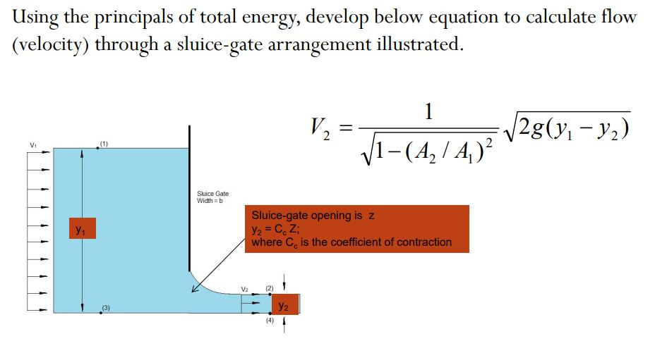
The energy equation for the sluice gate is based on the principle of conservation of energy, which states that the total energy of a fluid remains constant as it flows through the gate. The energy equation can be expressed as:
E1 + ΔE = E2
where E1 is the energy at the upstream side of the gate, ΔE is the change in energy, and E2 is the energy at the downstream side of the gate.
Introduction to Sluice Gate Energy Equation
The sluice gate energy equation is a fundamental concept in fluid mechanics and is used to calculate the energy losses that occur as water flows through the gate. The equation takes into account the kinetic energy, potential energy, and pressure energy of the fluid. The energy equation can be applied to various types of gates, including sluice gates, weirs, and dams.
- The energy equation is used to calculate the head loss that occurs as water flows through the gate.
- The head loss is a measure of the energy lost due to friction and other resistance forces.
- The energy equation can be used to design and optimize the performance of sluice gates and other hydraulic structures.
Components of the Energy Equation
The energy equation for the sluice gate consists of several components, including the kinetic energy, potential energy, and pressure energy of the fluid. The kinetic energy is related to the velocity of the fluid, while the potential energy is related to the elevation of the fluid. The pressure energy is related to the pressure of the fluid.
- The kinetic energy is a measure of the energy associated with the motion of the fluid.
- The potential energy is a measure of the energy associated with the elevation of the fluid.
- The pressure energy is a measure of the energy associated with the pressure of the fluid.
Application of the Energy Equation
The energy equation for the sluice gate has numerous applications in water resources engineering, including the design and operation of irrigation systems, flood control systems, and hydroelectric power plants. The equation can be used to calculate the flow rate, water level, and pressure of the fluid as it flows through the gate.
- The energy equation can be used to calculate the flow rate of water through the gate.
- The energy equation can be used to calculate the water level upstream and downstream of the gate.
- The energy equation can be used to calculate the pressure of the fluid as it flows through the gate.
Limitations of the Energy Equation
The energy equation for the sluice gate has several limitations, including the assumption of steady-state flow and the neglect of turbulence and other non-uniform flow effects. The equation is also limited by the accuracy of the empirical coefficients used to calculate the head loss and other energy losses.
- The energy equation assumes steady-state flow, which may not be valid for all types of flow.
- The energy equation neglects turbulence and other non-uniform flow effects, which can be significant in some cases.
- The energy equation requires empirical coefficients to calculate the head loss and other energy losses, which can be uncertain or inaccurate.
Future Developments in Energy Equation
Research is ongoing to improve the accuracy and applicability of the energy equation for the sluice gate, including the development of numerical models and experimental techniques to measure the energy losses and other flow characteristics. The use of computational fluid dynamics (CFD) and other numerical methods is becoming increasingly popular for simulating the flow through sluice gates and other hydraulic structures.
- Numerical models are being developed to simulate the flow through sluice gates and other hydraulic structures.
- Experimental techniques are being developed to measure the energy losses and other flow characteristics.
- Computational fluid dynamics (CFD) and other numerical methods are being used to simulate the flow through sluice gates and other hydraulic structures.
What is the contraction coefficient of a sluice gate?
The contraction coefficient of a sluice gate is a dimensionless value that represents the ratio of the discharge of the gate to the discharge of a hypothetical gate with no contraction. It is an important parameter in the design and operation of sluice gates, as it affects the flow rate and water level upstream and downstream of the gate. The contraction coefficient is typically denoted by the symbol μ and can be calculated using various empirical formulas or measured experimentally.
Definition and Calculation of Contraction Coefficient
The contraction coefficient is defined as the ratio of the actual discharge of the gate to the theoretical discharge of the gate, assuming no contraction. It can be calculated using the formula: μ = Q / (A sqrt(2 g H)), where Q is the actual discharge, A is the gate opening area, g is the acceleration due to gravity, and H is the upstream water head. The contraction coefficient can also be expressed as a function of the gate opening and water level.
- The contraction coefficient is a function of the gate opening and water level.
- The contraction coefficient can be calculated using empirical formulas or measured experimentally.
- The contraction coefficient is an important parameter in the design and operation of sluice gates.
Factors Affecting Contraction Coefficient
Several factors can affect the contraction coefficient of a sluice gate, including the gate opening, water level, gate shape, and flow regime. The contraction coefficient can also be affected by the presence of obstructions or debris in the gate opening. Additionally, the contraction coefficient can vary depending on the flow rate and water level.
- The gate opening can affect the contraction coefficient by changing the flow area.
- The water level can affect the contraction coefficient by changing the upstream water head.
- The gate shape can affect the contraction coefficient by changing the flow regime.
Importance of Contraction Coefficient in Sluice Gate Design
The contraction coefficient is a critical parameter in the design of sluice gates, as it affects the flow rate and water level upstream and downstream of the gate. A high contraction coefficient can result in a higher flow rate and lower water level upstream, while a low contraction coefficient can result in a lower flow rate and higher water level upstream. The contraction coefficient can also affect the stability and safety of the sluice gate.
- A high contraction coefficient can result in a higher flow rate and lower water level upstream.
- A low contraction coefficient can result in a lower flow rate and higher water level upstream.
- The contraction coefficient can affect the stability and safety of the sluice gate.
Measurement and Estimation of Contraction Coefficient
The contraction coefficient can be measured experimentally using various methods, including the velocity-area method and the flow-meter method. The contraction coefficient can also be estimated using empirical formulas, such as the Bazin formula and the Rehbock formula. The measurement and estimation of the contraction coefficient are important for the design and operation of sluice gates.
- The velocity-area method can be used to measure the contraction coefficient.
- The flow-meter method can be used to measure the contraction coefficient.
- The Bazin formula can be used to estimate the contraction coefficient.
Applications of Contraction Coefficient in Hydraulic Engineering
The contraction coefficient has various applications in hydraulic engineering, including the design and operation of sluice gates, dams, and canals. The contraction coefficient can also be used to predict and prevent floods and droughts. Additionally, the contraction coefficient can be used to optimize the performance of hydraulic structures.
- The contraction coefficient can be used to design and operate sluice gates.
- The contraction coefficient can be used to predict and prevent floods and droughts.
- The contraction coefficient can be used to optimize the performance of hydraulic structures.
Can a sluice gate be calibrated to measure flow?
A sluice gate can be calibrated to measure flow by using various methods to determine the relationship between the gate's opening and the resulting water flow rate. This calibration process typically involves measuring the flow rate at different gate openings and creating a rating curve that relates the two. The rating curve can then be used to estimate the flow rate based on the gate's opening.
Calibration Methods
The calibration of a sluice gate to measure flow can be achieved through several methods, including:
- The direct measurement method, which involves measuring the flow rate directly using a flow meter or other devices.
- The indirect measurement method, which involves measuring the water level or velocity upstream or downstream of the gate and using this data to estimate the flow rate.
- The theoretical calculation method, which involves using mathematical models and hydraulic principles to calculate the flow rate based on the gate's opening and other factors.
This method can provide accurate results if the sluice gate is properly maintained and the calibration is regularly updated.
Factors Affecting Calibration
Several factors can affect the calibration of a sluice gate to measure flow, including:
- The gate's opening, which can affect the flow rate and the pressure upstream and downstream of the gate.
- The water level, which can affect the flow rate and the pressure upstream and downstream of the gate.
- The velocity of the water, which can affect the flow rate and the pressure upstream and downstream of the gate.
These factors must be carefully considered during the calibration process to ensure accurate results.
Applications of Calibrated Sluice Gates
Calibrated sluice gates can be used in a variety of applications, including:
- Water supply systems, where accurate flow measurement is crucial for managing water resources.
- Irrigation systems, where flow measurement is necessary for optimizing water usage and reducing wastewater.
- Flood control systems, where flow measurement is critical for predicting and mitigating floods.
These applications rely on accurate flow measurement to function effectively.
Advantages of Calibrated Sluice Gates
The calibration of a sluice gate to measure flow offers several advantages, including:
- Improved accuracy, which is essential for making informed decisions about water management.
- Increased efficiency, which can be achieved by optimizing water usage and reducing wastewater.
- Enhanced reliability, which is critical for applications where flow measurement is essential for public health and safety.
These advantages make calibrated sluice gates a valuable tool for water resource management.
Challenges and Limitations
Despite the advantages of calibrated sluice gates, there are several challenges and limitations to consider, including:
- Maintenance requirements, which can be time-consuming and costly if not performed regularly.
- Sensor accuracy, which can be affected by environmental factors such as temperature and humidity.
- Data interpretation, which requires strong analytical skills to ensure accurate flow measurement.
These challenges and limitations must be carefully considered when using calibrated sluice gates for flow measurement.
Frequently Asked Questions (FAQs)
What is the Sluice Gate Flow Formula and how is it used in calculating flow rates?
The Sluice Gate Flow Formula is a mathematical equation used to calculate the flow rate of water through a sluice gate, which is a type of gate used to control the flow of water in canals, rivers, and other waterways. The formula takes into account the height of the water upstream and downstream of the gate, as well as the width of the gate and the coefficient of discharge, which is a value that depends on the specific design of the gate. The formula is typically expressed as Q = C_d A sqrt(2 g H), where Q is the flow rate, C_d is the coefficient of discharge, A is the cross-sectional area of the gate, g is the acceleration due to gravity, and H is the difference in water level between the upstream and downstream sides of the gate. By using this formula, engineers and hydrologists can accurately calculate the flow rate of water through a sluice gate and design the gate to meet specific hydraulic requirements.
How does the Sluice Gate Flow Calculator work and what are its limitations?
The Sluice Gate Flow Calculator is a software tool that uses the Sluice Gate Flow Formula to calculate the flow rate of water through a sluice gate. The calculator typically requires the user to input values such as the height of the water upstream and downstream of the gate, the width of the gate, and the coefficient of discharge. The calculator then uses these values to calculate the flow rate, which is typically expressed in units of cubic meters per second or cubic feet per second. However, the calculator has several limitations, including the assumption that the flow is steady and uniform, and that the gate is fully open or fully closed. In reality, the flow may be unsteady or non-uniform, and the gate may be partially open or partially closed, which can affect the accuracy of the calculation. Additionally, the calculator may not take into account other factors that can affect the flow rate, such as friction and turbulence.
What are the key factors that affect the flow rate of a sluice gate, and how can they be optimized?
The key factors that affect the flow rate of a sluice gate include the height of the water upstream and downstream of the gate, the width of the gate, and the coefficient of discharge. The height of the water upstream and downstream of the gate determines the head of the gate, which is the difference in water level between the two sides. A greater head results in a greater flow rate, while a smaller head results in a smaller flow rate. The width of the gate also affects the flow rate, with a wider gate resulting in a greater flow rate. The coefficient of discharge is a value that depends on the specific design of the gate and can be optimized by using a well-designed gate with a smooth and non-turbulent flow path. Other factors that can affect the flow rate include friction and turbulence, which can be minimized by using a smooth and well-maintained gate.
How can the Sluice Gate Flow Formula and Calculator be applied in real-world engineering and hydrological applications?
The Sluice Gate Flow Formula and Calculator can be applied in a variety of real-world engineering and hydrological applications, including the design and operation of canals, rivers, and waterways. For example, the formula and calculator can be used to design a new sluice gate or to optimize the performance of an existing gate. The formula and calculator can also be used to predict the flow rate of water through a gate under different hydrological scenarios, such as floods or droughts. Additionally, the formula and calculator can be used to evaluate the hydraulic performance of a gate and to identify potential problems or bottlenecks in the flow path. By using the Sluice Gate Flow Formula and Calculator, engineers and hydrologists can make informed decisions about the design and operation of sluice gates and other water control structures, which is critical for managing and conserving water resources in a sustainable and environmentally-friendly way.
Deja una respuesta
Entradas Relacionadas