
Sheet Metal Bend Line Distance To Mold Line Calculator

The Sheet Metal Bend Line Distance To Mold Line Calculator is a crucial tool for engineers and manufacturers working with sheet metal. It helps determine the precise distance from the bend line to the mold line, ensuring accurate and efficient production. By calculating this distance, users can optimize their design and manufacturing processes, reducing errors and improving overall product quality. This calculator is essential for various industries, including aerospace, automotive, and construction, where precise sheet metal fabrication is critical. It simplifies complex calculations, saving time and resources.
-
Understanding the Sheet Metal Bend Line Distance To Mold Line Calculator
- How to Use the Sheet Metal Bend Line Distance To Mold Line Calculator
- Benefits of Using the Sheet Metal Bend Line Distance To Mold Line Calculator
- Key Parameters in the Sheet Metal Bend Line Distance To Mold Line Calculator
- Common Applications of the Sheet Metal Bend Line Distance To Mold Line Calculator
- Limitations and Future Developments of the Sheet Metal Bend Line Distance To Mold Line Calculator
- What is the distance from the mold point to the bend tangent line?
- What is the minimum bend distance for sheet metal?
- What is the setback of sheet metal bend?
- What is the rule of thumb for bending sheet metal?
-
Frequently Asked Questions (FAQs)
- What is the purpose of the Sheet Metal Bend Line Distance To Mold Line Calculator?
- How does the Sheet Metal Bend Line Distance To Mold Line Calculator work?
- What are the benefits of using the Sheet Metal Bend Line Distance To Mold Line Calculator?
- Can the Sheet Metal Bend Line Distance To Mold Line Calculator be used for different types of sheet metal materials?
Understanding the Sheet Metal Bend Line Distance To Mold Line Calculator
The Sheet Metal Bend Line Distance To Mold Line Calculator is a tool designed to help engineers and manufacturers determine the optimal distance between the bend line and the mold line in sheet metal fabrication. This calculator takes into account various parameters, such as the material thickness, bend radius, and mold design, to provide an accurate calculation of the distance required for a successful bend.
How to Use the Sheet Metal Bend Line Distance To Mold Line Calculator
Using the calculator is a straightforward process that involves inputting the required parameters and selecting the desired units. The calculator will then perform the calculations based on complex algorithms and industry standards. The result will provide the optimal distance between the bend line and the mold line, allowing manufacturers to optimize their production process and reduce errors.
Benefits of Using the Sheet Metal Bend Line Distance To Mold Line Calculator
The calculator offers several benefits, including increased accuracy, reduced production time, and improved product quality. By using the calculator, manufacturers can eliminate trial and error methods, which can be time-consuming and costly. The calculator also allows for easy comparison of different design scenarios, enabling manufacturers to optimize their designs and improve their bottom line.
Key Parameters in the Sheet Metal Bend Line Distance To Mold Line Calculator
The calculator takes into account several key parameters, including:
| Parameter | Description |
|---|---|
| Material Thickness | The thickness of the sheet metal being used. |
| Bend Radius | The radius of the bend in the sheet metal. |
| Mold Design | The design of the mold being used to form the sheet metal. |
These parameters are critical in determining the optimal distance between the bend line and the mold line.
Common Applications of the Sheet Metal Bend Line Distance To Mold Line Calculator
The calculator has several common applications in the manufacturing industry, including automotive, aerospace, and industrial equipment. It is also used in the production of consumer goods, such as appliances and furniture. The calculator is an essential tool for any manufacturer that works with sheet metal and requires precise calculations to ensure quality and efficiency.
Limitations and Future Developments of the Sheet Metal Bend Line Distance To Mold Line Calculator
While the calculator is a powerful tool, it does have some limitations, such as the assumption of ideal conditions and the lack of consideration for complex geometries. Future developments of the calculator will focus on addressing these limitations and expanding its capabilities to include more complex scenarios. This will enable manufacturers to optimize their production processes even further and stay ahead of the competition.
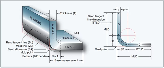
What is the distance from the mold point to the bend tangent line?
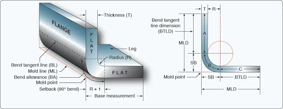
The distance from the mold point to the bend tangent line is a crucial aspect of bend design and manufacturing. It refers to the perpendicular distance from the point where the mold is positioned to the tangent line of the bend. This distance is essential in determining the bend radius and the overall geometry of the bent part.
Understanding Bend Geometry
The distance from the mold point to the bend tangent line is critical in understanding the bend geometry. To calculate this distance, one needs to consider the bend angle, bend radius, and the position of the mold. The following steps can be taken to determine this distance:
- Calculate the bend radius using the bend angle and the mold position.
- Determine the tangent line to the bend at the point of interest.
- Measure the perpendicular distance from the mold point to the tangent line.
Importance of Accurate Measurement
Accurate measurement of the distance from the mold point to the bend tangent line is crucial in bend manufacturing. Inaccurate measurements can lead to defects in the bent part, such as wrinkles or distortions. To ensure accurate measurements, precision instruments and techniques should be used. The following techniques can be employed:
- Use precision calipers or micrometers to measure the distance.
- Employ computer-aided design (CAD) software to simulate the bend and calculate the distance.
- Conduct quality control checks to verify the accuracy of the measurements.
Factors Affecting the Distance
Several factors can affect the distance from the mold point to the bend tangent line, including the material properties, bend angle, and mold design. The material properties, such as the yield strength and young's modulus, can influence the bend radius and the distance. The following factors can be considered:
- The material thickness and width can affect the bend radius and distance.
- The bend angle and mold position can influence the distance and bend geometry.
- The mold design and manufacturing process can impact the accuracy of the measurements.
Calculation Methods
There are several calculation methods available to determine the distance from the mold point to the bend tangent line, including geometric calculations and numerical simulations. The geometric calculations involve using trigonometry and geometry to calculate the distance. The following methods can be used:
- Use trigonometric functions to calculate the bend radius and distance.
- Employ numerical simulations, such as finite element analysis (FEA), to simulate the bend and calculate the distance.
- Utilize CAD software to simulate the bend and calculate the distance.
Applications and Limitations
The distance from the mold point to the bend tangent line has significant applications in bend manufacturing and design. However, there are also limitations to consider, such as the complexity of the bend geometry and the accuracy of the measurements. The following applications and limitations can be considered:
- The distance is crucial in bend design and manufacturing to ensure accuracy and quality.
- The complexity of the bend geometry can limit the accuracy of the measurements and calculations.
- The material properties and manufacturing process can impact the accuracy of the measurements and calculations.
What is the minimum bend distance for sheet metal?
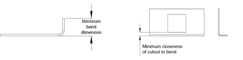
The minimum bend distance for sheet metal is a critical factor in determining the feasibility of a particular design or fabrication project. It refers to the minimum distance required between the edge of a sheet metal part and the start of a bend or fold. This distance is crucial in ensuring that the metal does not fracture or deform excessively during the bending process.
Understanding the Minimum Bend Distance
The minimum bend distance is influenced by several factors, including the type of material being used, its thickness, and the desired bend radius. A general rule of thumb is to maintain a minimum bend distance of at least 2-3 times the material thickness. For example, if the sheet metal is 1/8 inch thick, the minimum bend distance should be at least 1/4 to 3/8 inch. This can be broken down into the following key considerations:
- Material properties: The minimum bend distance may vary depending on the specific properties of the material, such as its yield strength and ductility.
- Bend radius: A smaller bend radius requires a shorter minimum bend distance, while a larger bend radius allows for a longer distance.
- Fabrication method: The minimum bend distance may also depend on the specific fabrication method being used, such as press braking or roll forming.
Factors Affecting the Minimum Bend Distance
Several factors can affect the minimum bend distance, including the tooling and equipment used, the operator's skill level, and the production volume. For instance, a more experienced operator may be able to achieve a tighter bend radius and shorter minimum bend distance than a less experienced one. Additionally, the use of specialized tooling or equipment can also impact the minimum bend distance. Some key factors to consider include:
- Tooling and equipment: The design and quality of the tooling and equipment can significantly impact the minimum bend distance.
- Operator's skill level: The skill and experience of the operator can affect the accuracy and consistency of the bend.
- Production volume: The production volume can influence the minimum bend distance, as higher volumes may require more efficient and automated processes.
Design Considerations for Minimum Bend Distance
When designing a sheet metal part, it is essential to consider the minimum bend distance to ensure that the part can be fabricated efficiently and accurately. This involves taking into account the geometry of the part, the material properties, and the fabrication method. Some key design considerations include:
- Part geometry: The design of the part should allow for a sufficient minimum bend distance to prevent distortion or fracture.
- Material selection: The selection of the material should be based on its mechanical properties and fabrication characteristics.
- Fabrication method: The choice of fabrication method should be based on the complexity of the part and the production volume.
Calculating the Minimum Bend Distance
Calculating the minimum bend distance involves considering several factors, including the material thickness, bend radius, and tooling. A general formula for calculating the minimum bend distance is: minimum bend distance = 2-3 x material thickness. However, this can vary depending on the specific application and fabrication method. Some key calculation steps include:
- Determine the material thickness: Measure the thickness of the sheet metal to determine the minimum bend distance.
- Determine the bend radius: Measure the bend radius to determine the minimum bend distance.
- Apply the formula: Apply the formula to calculate the minimum bend distance, taking into account any adjustments for tooling or equipment.
Best Practices for Working with Minimum Bend Distance
To ensure accurate and efficient fabrication of sheet metal parts, it is essential to follow best practices for working with minimum bend distance. This includes consulting with experienced fabricators, utilizing specialized tooling and equipment, and verifying the minimum bend distance through prototyping and testing. Some key best practices include:
- Consult with experienced fabricators: Consult with experienced fabricators to ensure that the minimum bend distance is accurate and feasible.
- Utilize specialized tooling and equipment: Utilize specialized tooling and equipment to achieve the required minimum bend distance.
- Verify the minimum bend distance: Verify the minimum bend distance through prototyping and testing to ensure that the part can be fabricated efficiently and accurately.
What is the setback of sheet metal bend?
The setback of sheet metal bend refers to the distortion that occurs when a sheet metal is bent, resulting in a change in the dimension and shape of the metal. This distortion can lead to inaccuracies in the final product, making it difficult to achieve the desired precision. The setback is influenced by various factors, including the type of metal, the thickness of the metal, and the bending angle.
Causes of Setback in Sheet Metal Bend
The causes of setback in sheet metal bend are complex and multifaceted. Some of the main causes include:
- Metal properties: The properties of the metal, such as its yield strength and elastic modulus, can affect the amount of setback that occurs.
- Bending process: The bending process itself can also contribute to setback, as the bending force and bending speed can cause the metal to deform.
- Tooling design: The design of the tooling used in the bending process can also impact the amount of setback, as improperly designed tools can cause uneven bending.
The setback can be minimized by carefully controlling these factors and using advanced bending techniques.
Effects of Setback on Sheet Metal Bend
The effects of setback on sheet metal bend can be significant, leading to dimensional inaccuracies and structural weaknesses. Some of the main effects include:
- Dimensional changes: The setback can cause the metal to change shape, resulting in inaccurate dimensions.
- Structural weaknesses: The setback can also lead to structural weaknesses, such as cracks and tears, which can compromise the integrity of the metal.
- Aesthetic issues: The setback can also affect the appearance of the metal, causing unsightly deformations and blemishes.
These effects can be mitigated by using advanced materials and sophisticated bending techniques.
Methods for Minimizing Setback in Sheet Metal Bend
There are several methods for minimizing setback in sheet metal bend, including:
- Using advanced materials: High-strength materials and advanced alloys can be used to reduce setback.
- Optimizing bending parameters: The bending force and bending speed can be optimized to minimize setback.
- Improving tooling design: The tooling design can be improved to reduce friction and prevent uneven bending.
These methods can help to reduce the setback and improve the accuracy of the bending process.
Tools and Techniques for Measuring Setback in Sheet Metal Bend
There are several tools and techniques that can be used to measure setback in sheet metal bend, including:
- Coordinate measuring machines: Coordinate measuring machines can be used to accurately measure the dimensions of the metal.
- Optical scanning: Optical scanning techniques can be used to create detailed maps of the metal's surface.
- Computer simulations: Computer simulations can be used to model the bending process and predict setback.
These tools and techniques can help to identify and quantify the setback, allowing for more accurate bending.
Applications of Setback in Sheet Metal Bend
The setback in sheet metal bend has significant implications for various industries, including:
- Aerospace industry: The aerospace industry requires high-precision bending to ensure the structural integrity of aircraft components.
- Automotive industry: The automotive industry also requires precise bending to ensure the safety and performance of vehicle components.
- Construction industry: The construction industry uses bent metal components in building frames and other structures.
Understanding and controlling the setback is crucial for these industries to produce high-quality products.
What is the rule of thumb for bending sheet metal?
The rule of thumb for bending sheet metal is to use a bending radius that is at least 1 to 2 times the thickness of the metal. This helps to prevent cracking and distortion of the metal. The bending process involves using a press brake or a bending machine to apply pressure to the metal, causing it to deform and take on the desired shape. The angle of the bend and the radius of the bend are critical factors in determining the success of the bending operation.
Understanding Bending Radius
The bending radius is a critical factor in determining the success of the bending operation. A bending radius that is too small can cause the metal to crack or distort, while a bending radius that is too large can result in a weak or unsatisfactory bend. The following are some key factors to consider when determining the bending radius:
- The thickness of the metal: thicker metals require a larger bending radius.
- The type of metal: different metals have different bending characteristics.
- The angle of the bend: a tighter angle requires a smaller bending radius.
Choosing the Right Bending Tool
The bending tool used can have a significant impact on the success of the bending operation. A press brake is a common tool used for bending sheet metal, but other tools such as a bending machine or a hand bender can also be used. The following are some key factors to consider when choosing a bending tool:
- The type of metal: different metals require different bending tools.
- The thickness of the metal: thicker metals require a more powerful bending tool.
- The angle of the bend: a tighter angle requires a more precise bending tool.
Measuring and Marking the Metal
Measuring and marking the metal are critical steps in the bending process. The metal must be measured accurately to ensure that the bend is in the correct location, and marked clearly to ensure that the bend is made in the correct direction. The following are some key factors to consider when measuring and marking the metal:
- Using a straightedge or ruler to measure the metal.
- Using a marker or pencil to mark the metal.
- Double-checking the measurements and marks to ensure accuracy.
Applying Pressure and Bending the Metal
Applying pressure and bending the metal are the final steps in the bending process. The pressure must be applied evenly and carefully to avoid distorting or damaging the metal. The following are some key factors to consider when applying pressure and bending the metal:
- Using a press brake or bending machine to apply pressure.
- Bending the metal slowly and carefully to avoid distortion.
- Checking the bend regularly to ensure that it is accurate and satisfactory.
Troubleshooting Common Bending Problems
Troubleshooting common bending problems is an essential part of the bending process. Cracking, distortion, and inaccurate bends are common problems that can occur during the bending process. The following are some key factors to consider when troubleshooting common bending problems:
- Checking the bending radius and angle of the bend.
- Inspecting the metal for defects or damage.
- Adjusting the bending tool or process to prevent problems from occurring.
Frequently Asked Questions (FAQs)
What is the purpose of the Sheet Metal Bend Line Distance To Mold Line Calculator?
The Sheet Metal Bend Line Distance To Mold Line Calculator is a tool designed to calculate the distance from the bend line to the mold line in sheet metal fabrication. This calculation is crucial in determining the accuracy and precision of the bending process. By using this calculator, manufacturers and engineers can ensure that their sheet metal parts are produced with the correct dimensions and tolerances. The calculator takes into account various parameters such as the material thickness, bend radius, and bend angle to provide an accurate calculation of the distance from the bend line to the mold line. This information is essential in the production of high-quality sheet metal parts, where precise calculations can make a significant difference in the final product's performance and reliability.
How does the Sheet Metal Bend Line Distance To Mold Line Calculator work?
The Sheet Metal Bend Line Distance To Mold Line Calculator works by using a set of complex algorithms and formulas to calculate the distance from the bend line to the mold line. The calculator requires input values such as the material thickness, bend radius, and bend angle, which are then used to calculate the bend allowance and bend deduction. These values are then used to determine the distance from the bend line to the mold line, taking into account the stretching and compressing of the material during the bending process. The calculator also considers the type of material being used, as different materials have different properties that can affect the bending process. By using this calculator, users can streamline their design and production processes, reducing the need for trial and error and prototypes.
What are the benefits of using the Sheet Metal Bend Line Distance To Mold Line Calculator?
The Sheet Metal Bend Line Distance To Mold Line Calculator offers several benefits to users, including increased accuracy and precision in the bending process. By using this calculator, manufacturers and engineers can reduce errors and improve quality in their sheet metal parts. The calculator also saves time and reduces costs associated with trial and error and prototyping. Additionally, the calculator can help users optimize their designs and production processes, resulting in improved efficiency and productivity. The calculator is also easy to use, with a user-friendly interface that requires minimal training and expertise. Overall, the Sheet Metal Bend Line Distance To Mold Line Calculator is a valuable tool for anyone involved in sheet metal fabrication, providing accurate and reliable calculations that can improve the quality and performance of their products.
Can the Sheet Metal Bend Line Distance To Mold Line Calculator be used for different types of sheet metal materials?
Yes, the Sheet Metal Bend Line Distance To Mold Line Calculator can be used for different types of sheet metal materials, including steel, aluminum, copper, and brass. The calculator is versatile and can accommodate various material properties, such as thickness, density, and elasticity. The calculator also considers the type of bend being used, such as V-bend, U-bend, or hemming, and can adjust the calculations accordingly. Additionally, the calculator can be configured to account for different bending processes, such as press braking, roll forming, or spin forming. By using this calculator, users can ensure accuracy and precision in their sheet metal parts, regardless of the material or bending process being used. The calculator is a powerful tool that can be used in a variety of applications, from simple sheet metal parts to complex assemblies and structures.
Deja una respuesta
Entradas Relacionadas