
Plastic Straight Bevel Gears Rated Design Hp, Operating Stress Equations and Calculator

The design and operation of plastic straight bevel gears is a complex process that requires careful consideration of various factors, including material properties, gear geometry, and operating conditions. To ensure reliable and efficient performance, engineers must accurately calculate the rated design horsepower and operating stress of these gears. This article provides an overview of the key equations and calculation methods used to determine the rated design horsepower and operating stress of plastic straight bevel gears, along with a useful calculator tool to simplify the process. Accurate calculations are crucial to prevent gear failure.
- Understanding Plastic Straight Bevel Gears: Rated Design Hp, Operating Stress Equations, and Calculator
- What is the formula for bevel gear?
- What is the maximum rpm for a bevel gear?
- What is a straight bevel gear?
- What is the gear ratio of a bevel gear?
-
Frequently Asked Questions (FAQs)
- What are Plastic Straight Bevel Gears and their applications?
- How are the Rated Design Hp and Operating Stress Equations calculated for Plastic Straight Bevel Gears?
- What is the purpose of a Calculator for Plastic Straight Bevel Gears?
- How can Operating Stress Equations be used to optimize the design of Plastic Straight Bevel Gears?
Understanding Plastic Straight Bevel Gears: Rated Design Hp, Operating Stress Equations, and Calculator
Plastic straight bevel gears are a type of gear used in various mechanical applications, including power transmission and motion control systems. These gears are designed to provide a high level of efficiency and durability, while also being resistant to wear and corrosion. In this context, the rated design hp (horsepower) of a plastic straight bevel gear refers to its maximum power handling capacity, which is determined by its design and materials. The operating stress equations are used to calculate the stress levels on the gear teeth and other components, ensuring that they can withstand the forces and loads applied to them. A calculator is often used to simplify these calculations and provide accurate results.
Introduction to Plastic Straight Bevel Gears
Plastic straight bevel gears are made from a variety of materials, including polyamide, polyurethane, and polyetheretherketone (PEEK). These materials offer excellent mechanical properties, such as high strength, stiffness, and resistance to fatigue. The gears are designed with a straight bevel shape, which provides a constant velocity ratio and smooth operation. They are commonly used in applications where high precision and low noise are required, such as in medical devices, aerospace, and industrial automation.
Rated Design Hp and Power Handling Capacity
The rated design hp of a plastic straight bevel gear is determined by its design and materials. It is calculated based on the gear's tooth profile, pitch diameter, and face width. The power handling capacity of the gear is also affected by the operating temperature, speed, and load conditions. A higher rated design hp indicates that the gear can handle more power and operate at higher speeds.
Operating Stress Equations and Calculations
The operating stress equations for plastic straight bevel gears are used to calculate the stress levels on the gear teeth and other components. These equations take into account the bending stress, contact stress, and root stress on the gear teeth, as well as the shaft stress and bearing stress on the surrounding components. The calculations involve the use of material properties, such as modulus of elasticity, Poisson's ratio, and ultimate tensile strength.
Calculator for Plastic Straight Bevel Gears
A calculator is often used to simplify the calculations and provide accurate results for plastic straight bevel gears. The calculator typically requires input values such as the gear's diameter, pitch, face width, and material properties. It then calculates the rated design hp, operating stress levels, and other key parameters. The calculator can also be used to optimize the gear design and select the most suitable materials and operating conditions.
Material Selection and Properties
The material selection for plastic straight bevel gears is critical to their performance and durability. The most common materials used are polyamide, polyurethane, and PEEK, which offer excellent mechanical properties and resistance to wear and corrosion. The material properties, such as modulus of elasticity, Poisson's ratio, and ultimate tensile strength, are used in the operating stress equations and calculations.
| Material | Modulus of Elasticity (GPa) | Poisson's Ratio | Ultimate Tensile Strength (MPa) |
|---|---|---|---|
| Polyamide | 2.5-3.5 | 0.3-0.4 | 80-120 |
| Polyurethane | 1.5-2.5 | 0.4-0.5 | 50-100 |
| PEEK | 3.5-4.5 | 0.3-0.4 | 100-150 |
The modulus of elasticity is a measure of the material's stiffness, while the Poisson's ratio is a measure of its lateral strain. The ultimate tensile strength is a measure of the material's maximum stress before failure. These properties are essential in determining the rated design hp and operating stress levels of plastic straight bevel gears.
What is the formula for bevel gear?
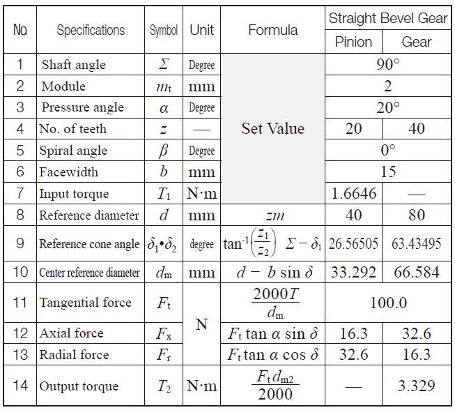
The formula for bevel gear is based on the pitch circle diameter and the number of teeth. The formula is: tan(∠A) = (N2 / N1) (D2 / D1), where ∠A is the angle between the gear axes, N1 and N2 are the number of teeth of the two gears, and D1 and D2 are the pitch circle diameters of the two gears.
Understanding Bevel Gear Formulas
The bevel gear formula is used to calculate the tooth profile and the pitch angle of the gear. The formula takes into account the number of teeth and the pitch circle diameter of the gear. The pitch circle diameter is the diameter of the circle that passes through the pitch point of the gear, which is the point where the tooth profile intersects the pitch circle.
- The number of teeth is an important factor in determining the tooth profile and the pitch angle of the gear.
- The pitch circle diameter is used to calculate the tooth profile and the pitch angle of the gear.
- The angle between the gear axes is also an important factor in determining the tooth profile and the pitch angle of the gear.
Bevel Gear Design Considerations
When designing a bevel gear, it is important to consider the load capacity, the speed, and the efficiency of the gear. The load capacity is determined by the number of teeth and the pitch circle diameter of the gear. The speed of the gear is determined by the pitch angle and the number of teeth.
- The load capacity of the gear should be determined based on the expected load and the material properties of the gear.
- The speed of the gear should be determined based on the expected speed and the efficiency of the gear.
- The efficiency of the gear should be determined based on the pitch angle and the number of teeth.
Bevel Gear Manufacturing Process
The manufacturing process for bevel gears involves several steps, including design, tooling, and machining. The design step involves creating a computer-aided design (CAD) model of the gear, which is then used to create a tooling model. The tooling model is used to create the machining program, which is used to machine the gear.
- The design step is critical in determining the tooth profile and the pitch angle of the gear.
- The tooling step is critical in determining the accuracy and the precision of the gear.
- The machining step is critical in determining the surface finish and the dimensional accuracy of the gear.
Bevel Gear Applications
Bevel gears are used in a variety of applications, including automotive, aerospace, and industrial. The automotive industry uses bevel gears in transmissions and differentials. The aerospace industry uses bevel gears in engine and transmission systems. The industrial industry uses bevel gears in machine tools and robots.
- The automotive industry requires high-performance and high-reliability bevel gears.
- The aerospace industry requires high-precision and high-reliability bevel gears.
- The industrial industry requires high-torque and high-efficiency bevel gears.
Bevel Gear Materials and Properties
Bevel gears are made from a variety of materials, including steel, aluminum, and plastics. The steel gears are strong and durable, but heavy. The aluminum gears are lightweight and corrosion-resistant, but weak. The plastics gears are lightweight and inexpensive, but weak and prone to wear.
- The steel gears are suitable for high-load and high-speed applications.
- The aluminum gears are suitable for low-load and low-speed applications.
- The plastics gears are suitable for low-load and low-speed applications where corrosion resistance is required.
What is the maximum rpm for a bevel gear?

The maximum rpm for a bevel gear depends on various factors, including the gear material, tooth size, and operating conditions. Generally, bevel gears are designed to operate at lower speeds than other types of gears, such as spur or helical gears. However, with advancements in gear manufacturing and materials technology, bevel gears can now operate at higher speeds and withstand more demanding applications.
Design Considerations
When designing a bevel gear, several factors must be considered to determine the maximum rpm. These include the gear ratio, tooth profile, and bearing capacity. A well-designed bevel gear must balance efficiency, durability, and noise reduction. Factors affecting the maximum rpm of a bevel gear include:
- The material selection and its fatigue strength
- The tooth size and pitch diameter
- The operating temperature and lubrication conditions
Material Selection
The choice of material is crucial in determining the maximum rpm of a bevel gear. High-strength materials such as steel or titanium can withstand higher speeds and loads than lower-strength materials like brass or plastics. Additionally, the surface finish and heat treatment of the gear can also impact its performance and durability. Key considerations for material selection include:
- The yield strength and tensile strength of the material
- The corrosion resistance and wear resistance
- The availability and cost of the material
Operational Factors
The operating conditions of the bevel gear also play a significant role in determining its maximum rpm. Factors such as temperature, humidity, and vibration can affect the gear's performance and lifetime. Additionally, the type of lubrication and maintenance schedule can also impact the gear's efficiency and reliability. Important operational factors to consider include:
- The ambient temperature and temperature fluctuations
- The type of load and load cycles
- The maintenance schedule and lubrication frequency
The manufacturing process used to create the bevel gear can also impact its maximum rpm. Advanced manufacturing techniques such as CNC machining or 3D printing can produce gears with higher precision and better surface finish, resulting in improved performance and durability. Key manufacturing considerations include:
- The machining tolerances and surface finish
- The material removal rate and tool wear
- The inspection and testing procedures
Application-Specific Considerations
The application in which the bevel gear is used can also dictate its maximum rpm. High-speed applications such as aerospace or automotive require gears that can withstand high rotational velocities and loads. In contrast, low-speed applications like industrial machinery or agricultural equipment may require gears with lower speeds and higher torque. Important application-specific considerations include:
- The required power transmission and torque
- The available space and weight constraints
- The noise reduction and vibration requirements
What is a straight bevel gear?

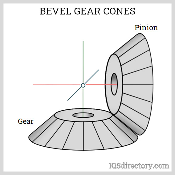
A straight bevel gear is a type of gear that has a conical shape with straight teeth. It is used to transmit power between two shafts that are at an angle to each other, typically at a 90-degree angle. The straight bevel gear is designed to provide a smooth and efficient transfer of power between the shafts, and is commonly used in applications where a change in direction of the power flow is required.
Design and Construction
The design and construction of a straight bevel gear is critical to its performance and efficiency. The gear is typically made from a high-strength material, such as steel or aluminum, and is manufactured using a precision machining process. The straight bevel gear has a number of key components, including the teeth, which are the pointed parts of the gear that mesh with the teeth of the other gear, and the hub, which is the central part of the gear that attaches to the shaft. Some of the key features of straight bevel gears include:
- Straight teeth, which provide a smooth and efficient transfer of power
- Conical shape, which allows for a change in direction of the power flow
- High-strength materials, which provide durability and resistance to wear and tear
Applications and Uses
Straight bevel gears are used in a wide range of applications, including automotive, industrial, and aerospace. They are commonly used in transmissions, differentials, and gearboxes, where a change in direction of the power flow is required. The straight bevel gear is also used in machine tools, such as lathes and milling machines, where a high degree of precision and accuracy is required. Some of the key applications of straight bevel gears include:
- Power transmission, where a change in direction of the power flow is required
- Machine tools, where a high degree of precision and accuracy is required
- Automotive applications, such as transmissions and differentials
Advantages and Benefits
The straight bevel gear has a number of advantages and benefits, including high efficiency, high precision, and low maintenance. The gear is designed to provide a smooth and efficient transfer of power, and is capable of handling high loads and high speeds. The straight bevel gear is also relatively simple and inexpensive to manufacture, making it a popular choice for many industrial and automotive applications. Some of the key advantages of straight bevel gears include:
- High efficiency, which provides a smooth and efficient transfer of power
- High precision, which provides a high degree of accuracy and precision
- Low maintenance, which reduces the need for regular maintenance and repair
Types and Variations
There are several types and variations of straight bevel gears, including single-pitch and double-pitch gears. The single-pitch gear has a single set of teeth, while the double-pitch gear has two sets of teeth, one on either side of the gear. The straight bevel gear can also be modified to suit specific applications, such as hollow or solid gears. Some of the key types and variations of straight bevel gears include:
- Single-pitch gears, which have a single set of teeth
- Double-pitch gears, which have two sets of teeth
- Hollow gears, which have a hollow center
Manufacturing and Production
The manufacturing and production of straight bevel gears involves a number of processes, including design, machining, and inspecting. The gear is typically designed using computer-aided design (CAD) software, and is manufactured using a precision machining process. The straight bevel gear is then inspected to ensure that it meets the required standards and specifications. Some of the key steps involved in the manufacturing and production of straight bevel gears include:
- Design, which involves creating a detailed design of the gear using CAD software
- Machining, which involves using a precision machining process to manufacture the gear
- Inspecting, which involves checking the gear to ensure that it meets the required standards and specifications
What is the gear ratio of a bevel gear?
The gear ratio of a bevel gear is the ratio of the rotational speed of the input gear to the rotational speed of the output gear. It is calculated by dividing the number of teeth on the output gear by the number of teeth on the input gear. Bevel gears are used to transmit power between two shafts that are at an angle to each other, and the gear ratio is critical in determining the torque and speed of the output shaft.
Understanding Bevel Gear Ratio
The bevel gear ratio is an important factor in the design and operation of mechanical systems. A high gear ratio can result in a high torque output, but a low speed output, while a low gear ratio can result in a high speed output, but a low torque output. The gear ratio is typically expressed as a ratio of the number of teeth on the output gear to the number of teeth on the input gear. For example, a gear ratio of 2:1 means that the output gear will rotate at half the speed of the input gear, but with twice the torque.
- The gear ratio is calculated by dividing the number of teeth on the output gear by the number of teeth on the input gear.
- A high gear ratio can result in a high torque output, but a low speed output.
- A low gear ratio can result in a high speed output, but a low torque output.
Calculating Bevel Gear Ratio
To calculate the bevel gear ratio, you need to know the number of teeth on the input and output gears. The gear ratio can be calculated using the following formula: gear ratio = number of teeth on output gear / number of teeth on input gear. For example, if the input gear has 20 teeth and the output gear has 40 teeth, the gear ratio would be 2:1.
- Know the number of teeth on the input and output gears.
- Use the formula gear ratio = number of teeth on output gear / number of teeth on input gear.
- Calculate the gear ratio using the formula.
Types of Bevel Gears
There are several types of bevel gears, including straight bevel gears, spiral bevel gears, and hypoid bevel gears. Each type of bevel gear has its own unique characteristics and applications. Straight bevel gears are the most common type of bevel gear and are used in a wide range of applications. Spiral bevel gears are used in applications where a high torque output is required, while hypoid bevel gears are used in applications where a high speed output is required.
- Straight bevel gears are the most common type of bevel gear.
- Spiral bevel gears are used in applications where a high torque output is required.
- Hypoid bevel gears are used in applications where a high speed output is required.
Applications of Bevel Gears
Bevel gears are used in a wide range of applications, including automotive, aerospace, and industrial. They are used to transmit power between two shafts that are at an angle to each other, and are commonly used in gearboxes, transmissions, and differentials. Bevel gears are also used in robotics and machine tools.
- Bevel gears are used in automotive, aerospace, and industrial applications.
- They are used to transmit power between two shafts that are at an angle to each other.
- Bevel gears are commonly used in gearboxes, transmissions, and differentials.
Design Considerations for Bevel Gears
When designing bevel gears, there are several factors to consider, including the gear ratio, torque, and speed. The gear ratio must be chosen to provide the required torque and speed output, while the materials and manufacturing process must be chosen to provide the required strength and durability. The design of the bevel gear must also take into account the loading and stress that the gear will be subjected to.
- The gear ratio must be chosen to provide the required torque and speed output.
- The materials and manufacturing process must be chosen to provide the required strength and durability.
- The design of the bevel gear must take into account the loading and stress that the gear will be subjected to.
Frequently Asked Questions (FAQs)
What are Plastic Straight Bevel Gears and their applications?
Plastic straight bevel gears are a type of gear that is made from plastic materials and is used to transmit rotational motion between two shafts that are at an angle to each other. These gears are commonly used in applications where low noise and low vibration are required, such as in medical devices, robotics, and aerospace industries. The use of plastic materials in the construction of these gears provides several advantages, including corrosion resistance, lightweight, and low maintenance. Additionally, plastic straight bevel gears can be designed to have a high gear ratio, which allows for a significant reduction in speed and increase in torque. This makes them ideal for use in applications where a high torque output is required, such as in gearboxes and transmissions.
How are the Rated Design Hp and Operating Stress Equations calculated for Plastic Straight Bevel Gears?
The rated design Hp and operating stress equations for plastic straight bevel gears are calculated using a combination of mathematical models and experimental data. The rated design Hp is calculated based on the gear's ability to withstand a certain amount of horsepower without failing, and is typically expressed in terms of the gear's tooth size, material properties, and operating conditions. The operating stress equations, on the other hand, are used to calculate the stress that is exerted on the gear during operation, and are typically based on the gear's tooth shape, material properties, and loading conditions. These calculations are critical in ensuring that the plastic straight bevel gear is designed to withstand the stresses and loads that it will experience during operation, and are typically performed using computer-aided design (CAD) software and finite element analysis (FEA) tools. By using these calculations and simulations, designers can optimize the design of the plastic straight bevel gear to ensure that it meets the required performance and reliability standards.
What is the purpose of a Calculator for Plastic Straight Bevel Gears?
A calculator for plastic straight bevel gears is a tool that is used to calculate the design parameters and performance characteristics of these gears. The calculator typically takes into account various input parameters, such as the gear's tooth size, material properties, and operating conditions, and uses mathematical models and algorithms to calculate the output parameters, such as the gear's rated design Hp, operating stress, and efficiency. The purpose of the calculator is to provide designers and engineers with a quick and accurate way to design and optimize plastic straight bevel gears, and to ensure that they meet the required performance and reliability standards. By using a calculator, designers can save time and reduce errors, and can focus on optimizing the design of the gear to meet the specific requirements of the application. Additionally, the calculator can be used to compare different design options and to identify the most suitable gear design for a particular application.
How can Operating Stress Equations be used to optimize the design of Plastic Straight Bevel Gears?
The operating stress equations can be used to optimize the design of plastic straight bevel gears by providing a quantitative understanding of the stresses that are exerted on the gear during operation. By using these equations, designers can identify the critical stress points in the gear and optimize the design to minimize these stresses. This can be achieved by modifying the gear's tooth shape, material properties, and loading conditions, and by using advanced materials and manufacturing techniques to reduce the stress concentrations. Additionally, the operating stress equations can be used to predict the fatigue life of the gear, which is critical in ensuring that the gear meets the required reliability standards. By using these equations and simulations, designers can optimize the design of the plastic straight bevel gear to ensure that it meets the required performance and reliability standards, and to reduce the risk of failure. Furthermore, the operating stress equations can be used to develop new materials and designs that are optimized for high-performance applications, such as aerospace and automotive industries.
Deja una respuesta
Entradas Relacionadas