
Op-Amp Gain Design Equation and Calculator

The operational amplifier (Op-Amp) is a crucial component in electronic circuits, providing amplification and signal processing capabilities. When designing with Op-Amps, calculating the gain is essential to ensure the desired output. The Op-Amp gain design equation is a fundamental formula used to determine the gain of an amplifier circuit. This equation takes into account the feedback resistor and input resistor values, allowing designers to calculate the exact gain required for their application. A gain calculator can simplify this process, providing an efficient way to determine the optimal resistor values for a specific gain.
- Understanding Op-Amp Gain Design Equation and Calculator
- How do you calculate the gain of an amp?
- How do you calculate the gain of a non inverting amp?
- How do you derive the gain of an op-amp?
-
Frequently Asked Questions (FAQs)
- What is the Op-Amp Gain Design Equation and how does it work?
- How do I use the Op-Amp Gain Design Calculator to determine the gain of my circuit?
- What are the key factors that affect the gain of an op-amp circuit, and how can I control them?
- Can I use the Op-Amp Gain Design Equation and Calculator to design circuits with multiple op-amps, and what are the limitations?
Understanding Op-Amp Gain Design Equation and Calculator
The Op-Amp Gain Design Equation and Calculator is a crucial tool for designing and analyzing operational amplifier circuits. The gain of an op-amp is a critical parameter that determines the amplification of the input signal. The gain design equation is used to calculate the required resistor values to achieve a specific gain. A calculator is often used to simplify the process and ensure accurate results.
Introduction to Op-Amp Gain Design
The op-amp gain design equation is based on the inverting amplifier configuration, where the input signal is applied to the inverting input of the op-amp. The gain of the amplifier is determined by the ratio of the feedback resistor to the input resistor. The equation for the gain of an inverting amplifier is given by:
A = -Rf / Ri, where A is the gain, Rf is the feedback resistor, and Ri is the input resistor.
Op-Amp Gain Design Equation
The op-amp gain design equation is a mathematical formula that calculates the required resistor values to achieve a specific gain. The equation takes into account the desired gain, the input impedance, and the output impedance. The equation is as follows:
Rf = (A Ri) / (1 + A), where Rf is the feedback resistor, A is the desired gain, and Ri is the input resistor.
Using an Op-Amp Gain Calculator
An op-amp gain calculator is a software tool that simplifies the process of designing an op-amp circuit. The calculator takes into account the desired gain, the input impedance, and the output impedance, and calculates the required resistor values. The calculator can also be used to analyze existing circuits and determine the gain of the amplifier.
Understanding Op-Amp Gain Calculator Results
The results of an op-amp gain calculator typically include the required resistor values, the gain of the amplifier, and the input and output impedances. The results can be used to design and build an op-amp circuit that meets the specifications. It is essential to understand the results and interpret them correctly to ensure that the circuit functions as expected.
Applications of Op-Amp Gain Design Equation and Calculator
The op-amp gain design equation and calculator have numerous applications in electronic circuit design. They are used in a wide range of fields, including audio equipment, medical devices, and industrial control systems. The equation and calculator are also used in academic research and education to teach students about op-amp circuits and design principles.
| Parameter | Description | Unit |
|---|---|---|
| Gain | The amplification of the input signal | dB or ratio |
| Input Impedance | The impedance of the input circuit | Ohms |
| Output Impedance | The impedance of the output circuit | Ohms |
| Feedback Resistor | The resistor that provides feedback to the op-amp | Ohms |
| Input Resistor | The resistor that connects the input signal to the op-amp | Ohms |
How do you calculate the gain of an amp?
To calculate the gain of an amplifier, you need to know the input voltage and the output voltage. The gain is calculated by dividing the output voltage by the input voltage. This can be expressed mathematically as: Gain (A) = Output Voltage (Vout) / Input Voltage (Vin). For example, if the input voltage is 1 volt and the output voltage is 10 volts, the gain of the amplifier would be 10.
Understanding Amplifier Gain
The gain of an amplifier is a measure of how much the amplifier amplifies the input signal. A higher gain means that the amplifier will produce a larger output signal. The gain of an amplifier can be expressed in terms of decibels (dB), which is a logarithmic unit that represents the ratio of the output power to the input power. To calculate the gain in decibels, you can use the following formula: Gain (dB) = 20 log10 (Vout / Vin).
- The gain of an amplifier is an important factor in determining its suitability for a particular application.
- A higher gain can be beneficial in certain situations, such as when trying to amplify a weak signal.
- However, a higher gain can also introduce more noise and distortion into the signal.
Types of Amplifier Gain
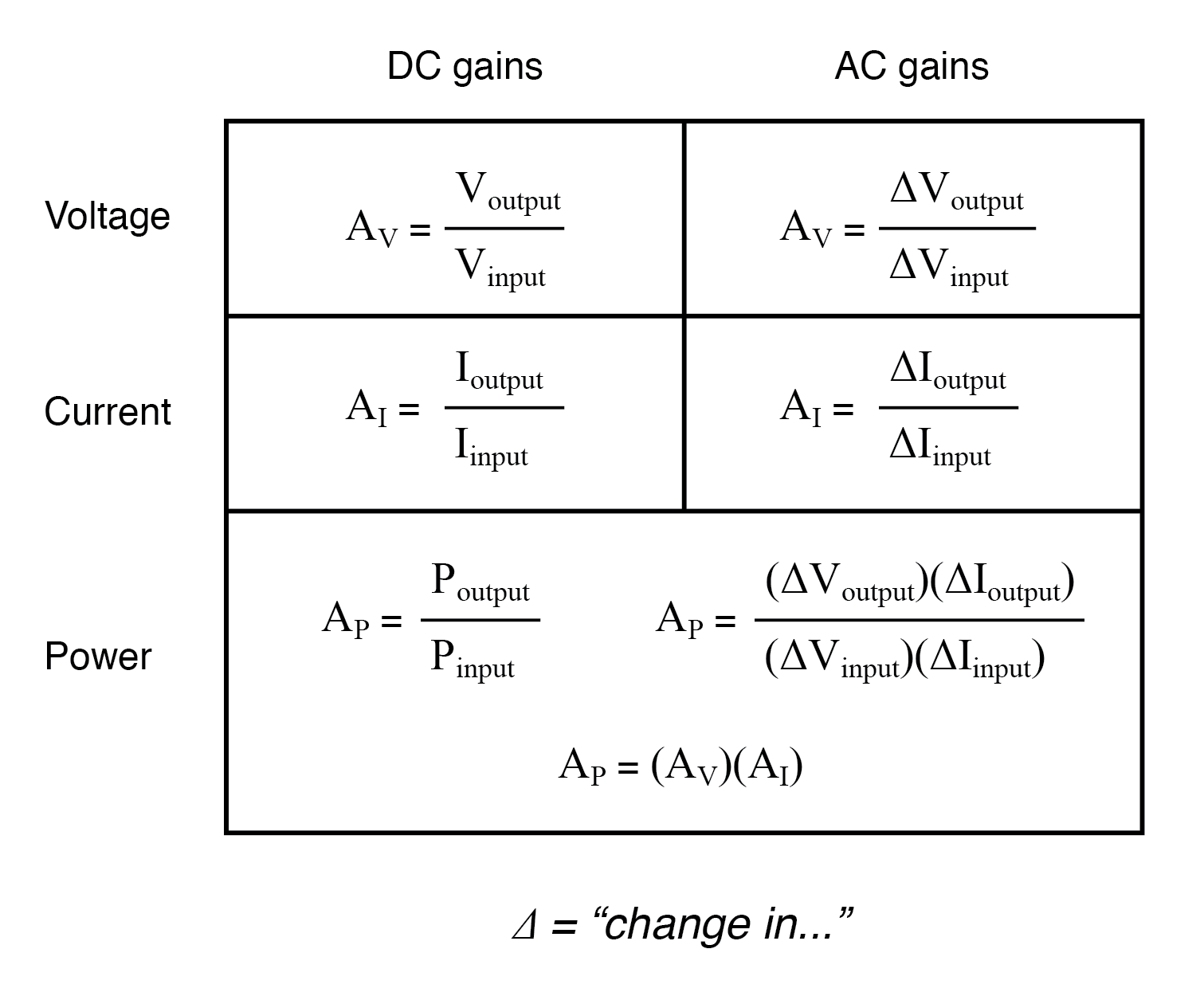
There are different types of gain that can be measured in an amplifier, including voltage gain, current gain, and power gain. The voltage gain is the ratio of the output voltage to the input voltage, while the current gain is the ratio of the output current to the input current. The power gain is the ratio of the output power to the input power.
- The voltage gain is the most commonly used measure of gain in an amplifier.
- The current gain is important in applications where the output current is critical.
- The power gain is a measure of the overall amplification of the signal.
Factors Affecting Amplifier Gain
The gain of an amplifier can be affected by several factors, including the input impedance, the output impedance, and the frequency of the signal. The input impedance can affect the gain by loading the input signal, while the output impedance can affect the gain by loading the output signal. The frequency of the signal can also affect the gain, as some amplifiers may have a frequency-dependent gain.
- The input impedance should be high to avoid loading the input signal.
- The output impedance should be low to avoid loading the output signal.
- The frequency of the signal should be within the bandwidth of the amplifier.
Measuring Amplifier Gain
The gain of an amplifier can be measured using a variety of techniques, including the use of oscilloscopes, spectrum analyzers, and signal generators. The gain can be measured by applying a known input signal to the amplifier and measuring the output signal. The gain can then be calculated by dividing the output signal by the input signal.
- The gain should be measured at multiple frequencies to ensure that it is frequency-independent.
- The gain should be measured at multiple amplitudes to ensure that it is linear.
- The gain should be measured using a high-impedance input to avoid loading the input signal.
Amplifier Gain Applications
The gain of an amplifier is an important factor in many electronic applications, including audio systems, instrumentation, and communication systems. A high gain amplifier can be used to amplify a weak signal in audio systems, while a low gain amplifier can be used to buffer a signal in instrumentation.
- A high gain amplifier can be used to amplify a weak signal in audio systems.
- A low gain amplifier can be used to buffer a signal in instrumentation.
- A variable gain amplifier can be used to control the amplitude of a signal in communication systems.
How do you calculate the gain of a non inverting amp?
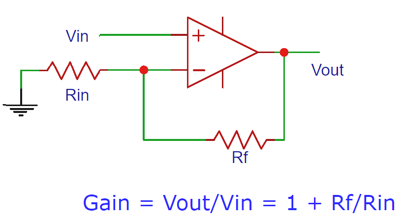
To calculate the gain of a non-inverting amplifier, you can use the formula: Gain (A) = 1 + (R2/R1), where R2 is the resistance of the feedback resistor and R1 is the resistance of the input resistor. This formula is derived from the fact that the non-inverting amplifier has a voltage divider at its input, which divides the input voltage by a factor of (R1/R2 + 1).
Understanding the Non-Inverting Amplifier Configuration
The non-inverting amplifier configuration is a type of operational amplifier circuit where the input signal is applied to the non-inverting input of the op-amp. This configuration is commonly used in audio amplifiers and instrumentation amplifiers. To calculate the gain of a non-inverting amplifier, you need to know the values of the feedback resistor (R2) and the input resistor (R1). The gain of the amplifier can be calculated using the formula:
- Identify the values of R2 and R1 in the circuit
- Plug these values into the formula: Gain (A) = 1 + (R2/R1)
- Calculate the gain of the amplifier using the formula
The Role of Feedback in Non-Inverting Amplifiers
Feedback is a crucial component in non-inverting amplifiers, as it allows the amplifier to stabilize its output and improve its linearity. The feedback resistor (R2) provides a path for the output signal to be fed back to the input of the amplifier, which reduces the overall gain of the amplifier. The feedback also improves the input impedance of the amplifier, making it more suitable for high-impedance sources. The key points to consider when designing a non-inverting amplifier with feedback are:
- The feedback resistor (R2) should be chosen to provide the desired amount of feedback
- The input resistor (R1) should be chosen to provide the desired input impedance
- The gain of the amplifier should be calculated using the formula: Gain (A) = 1 + (R2/R1)
Design Considerations for Non-Inverting Amplifiers
When designing a non-inverting amplifier, there are several key considerations to keep in mind. The input impedance of the amplifier should be high enough to avoid loading the source, and the output impedance should be low enough to drive the load. The gain of the amplifier should be stable and consistent, and the bandwidth should be wide enough to accommodate the frequency range of the input signal. Some important design considerations for non-inverting amplifiers are:
- The input impedance should be high enough to avoid loading the source
- The output impedance should be low enough to drive the load
- The gain of the amplifier should be stable and consistent
Common Applications of Non-Inverting Amplifiers
Non-inverting amplifiers are commonly used in a wide range of applications, including audio amplifiers, instrumentation amplifiers, and medical devices. They are particularly useful in applications where a high input impedance and a low output impedance are required. Some common applications of non-inverting amplifiers include:
- Audio amplifiers: to amplify audio signals with a high input impedance
- Instrumentation amplifiers: to amplify low-level signals from sensors and transducers
- Medical devices: to amplify biomedical signals from electrodes and sensors
Calculating the Gain of a Non-Inverting Amplifier with a Voltage Divider
When a voltage divider is used at the input of a non-inverting amplifier, the gain of the amplifier can be affected. The voltage divider reduces the input voltage to the amplifier, which reduces the overall gain of the amplifier. To calculate the gain of a non-inverting amplifier with a voltage divider, you need to know the values of the feedback resistor (R2), the input resistor (R1), and the voltage divider resistors (R3 and R4). The gain of the amplifier can be calculated using the formula:
- Identify the values of R2, R1, R3, and R4 in the circuit
- Calculate the voltage gain of the voltage divider using the formula: Voltage Gain = (R3/R4 + 1)
- Calculate the gain of the amplifier using the formula: Gain (A) = (1 + (R2/R1)) Voltage Gain
How do you derive the gain of an op-amp?

The gain of an operational amplifier (op-amp) is derived using the ideal op-amp model, which assumes that the op-amp has infinite input impedance, zero output impedance, and infinite gain. To derive the gain, we start with the ideal op-amp equation: Vo = A(V+ - V-), where Vo is the output voltage, A is the open-loop gain, V+ is the non-inverting input voltage, and V- is the inverting input voltage.
Understanding the Ideal Op-Amp Model
The ideal op-amp model is used to simplify the analysis of op-amp circuits. This model assumes that the op-amp has infinite input impedance, which means that it does not draw any current from the input sources. Additionally, it assumes that the op-amp has zero output impedance, which means that it can supply any amount of current to the output load. The ideal op-mp model also assumes that the op-amp has infinite gain, which means that it can amplify even the smallest input signal.
- The ideal op-amp model is a simplified model that is used to analyze op-amp circuits.
- The model assumes that the op-amp has infinite input impedance, zero output impedance, and infinite gain.
- The ideal op-amp model is useful for understanding the basic operation of op-amp circuits, but it does not accurately model the behavior of real op-amps.
Deriving the Gain of an Inverting Op-Amp
To derive the gain of an inverting op-amp, we start with the ideal op-amp equation: Vo = A(V+ - V-). We then apply the feedback principle, which states that the output voltage is fed back to the inverting input through a resistor. This creates a voltage divider that reduces the input voltage. The gain of the inverting op-amp is then given by: Av = -Rf/Rin, where Rf is the feedback resistor and Rin is the input resistor.
- The gain of an inverting op-amp is given by: Av = -Rf/Rin.
- The feedback principle is used to derive the gain of the inverting op-amp.
- The voltage divider created by the feedback resistor and the input resistor reduces the input voltage.
Deriving the Gain of a Non-Inverting Op-Amp
To derive the gain of a non-inverting op-amp, we start with the ideal op-amp equation: Vo = A(V+ - V-). We then apply the feedback principle, which states that the output voltage is fed back to the inverting input through a resistor. This creates a voltage divider that reduces the input voltage. The gain of the non-inverting op-amp is then given by: Av = 1 + Rf/Rin, where Rf is the feedback resistor and Rin is the input resistor.
- The gain of a non-inverting op-amp is given by: Av = 1 + Rf/Rin.
- The feedback principle is used to derive the gain of the non-inverting op-amp.
- The voltage divider created by the feedback resistor and the input resistor reduces the input voltage.
Understanding the Role of Feedback in Op-Amp Circuits
Feedback plays a crucial role in op-amp circuits, as it allows the output voltage to be fed back to the input, creating a voltage divider that reduces the input voltage. The feedback principle is used to derive the gain of both inverting and non-inverting op-amps. The type of feedback used (either negative or positive) determines the stability and accuracy of the op-amp circuit.
- Feedback is used to create a voltage divider that reduces the input voltage.
- The feedback principle is used to derive the gain of both inverting and non-inverting op-amps.
- The type of feedback used (either negative or positive) determines the stability and accuracy of the op-amp circuit.
Calculating the Gain of an Op-Amp Circuit
To calculate the gain of an op-amp circuit, we need to know the values of the input resistor (Rin) and the feedback resistor (Rf). We can then use the gain equation (either Av = -Rf/Rin for an inverting op-amp or Av = 1 + Rf/Rin for a non-inverting op-amp) to calculate the gain. The gain is a measure of how much the op-amp amplifies the input signal.
- The gain of an op-amp circuit can be calculated using the gain equation.
- The input resistor (Rin) and the feedback resistor (Rf) are used to calculate the gain.
- The gain is a measure of how much the op-amp amplifies the input signal.
Frequently Asked Questions (FAQs)
What is the Op-Amp Gain Design Equation and how does it work?
The Op-Amp Gain Design Equation is a fundamental concept in electronic circuit design, particularly when working with operational amplifiers. It is used to calculate the gain of an op-amp circuit, which is essential in determining the amplification of the input signal. The equation takes into account the resistor values and configuration of the circuit, allowing designers to predict and control the gain of the amplifier. The gain of an op-amp circuit is defined as the ratio of the output voltage to the input voltage, and it is typically expressed in decibels (dB) or as a dimensionless ratio. By using the Op-Amp Gain Design Equation, designers can optimize the performance of their circuits, ensuring that they meet the required specifications and standards.
How do I use the Op-Amp Gain Design Calculator to determine the gain of my circuit?
The Op-Amp Gain Design Calculator is a powerful tool that allows designers to quickly and easily determine the gain of their op-amp circuit. To use the calculator, simply enter the values of the resistors and capacitors in the circuit, as well as the desired gain or frequency response. The calculator will then compute the gain of the circuit, taking into account the configuration and components used. The calculator can also be used to simulate the behavior of the circuit, allowing designers to test and optimize their design before prototyping. By using the Op-Amp Gain Design Calculator, designers can save time and reduce errors, ensuring that their circuits meet the required performance and reliability standards. The calculator is particularly useful for complex circuits, where the gain and frequency response are critical to the overall functionality.
What are the key factors that affect the gain of an op-amp circuit, and how can I control them?
The gain of an op-amp circuit is affected by several key factors, including the resistor values, capacitor values, and op-amp specifications. The resistor values determine the feedback and input resistances, which in turn affect the gain of the circuit. The capacitor values determine the frequency response of the circuit, and can be used to filter or condition the input signal. The op-amp specifications, such as the gain-bandwidth product and slew rate, also play a critical role in determining the overall gain and performance of the circuit. To control the gain of an op-amp circuit, designers can adjust the resistor values, add or remove capacitors, or select a different op-amp with the desired specifications. By carefully optimizing these factors, designers can achieve the desired gain and frequency response, while also ensuring that the circuit meets the required power and noise standards.
Can I use the Op-Amp Gain Design Equation and Calculator to design circuits with multiple op-amps, and what are the limitations?
Yes, the Op-Amp Gain Design Equation and Calculator can be used to design circuits with multiple op-amps, such as multi-stage amplifiers or active filters. However, there are some limitations and considerations that must be taken into account. When designing circuits with multiple op-amps, the interaction between the stages must be carefully considered, as it can affect the overall gain and frequency response of the circuit. Additionally, the loading and biasing of each stage must be carefully managed, to ensure that the circuit operates stably and reliably. The Op-Amp Gain Design Calculator can be used to simulate the behavior of multi-stage circuits, allowing designers to optimize the performance and troubleshoot any issues that may arise. However, the calculator may not be able to accurately predict the behavior of very complex circuits, and experimental verification may be necessary to ensure that the circuit meets the required specifications and standards.
Deja una respuesta
Entradas Relacionadas