
Nozzle Venturi and Orifice Flowmeter Formula and Calculator

The Venturi nozzle and orifice flowmeters are widely used for measuring flow rates in various industrial applications. These devices work on the principle of differential pressure, where a constriction in the flow path creates a pressure drop that is directly proportional to the flow rate. The Venturi nozzle and orifice flowmeter formula is used to calculate the flow rate based on the pressure drop and the geometry of the meter. This article provides an overview of the formula and a calculator to simplify the calculations and improve the accuracy of flow rate measurements. Accurate flow rate measurement is crucial.
- Nozzle Venturi and Orifice Flowmeter Formula and Calculator
- What is the formula for the Venturi flowmeter?
- What is the formula for flow rate through nozzle?
- What is the formula for flowmeter?
-
Frequently Asked Questions (FAQs)
- What is the principle behind the Nozzle Venturi and Orifice Flowmeter Formula and Calculator?
- How does the Nozzle Venturi and Orifice Flowmeter Formula and Calculator work?
- What are the advantages of using the Nozzle Venturi and Orifice Flowmeter Formula and Calculator?
- How can the Nozzle Venturi and Orifice Flowmeter Formula and Calculator be applied in real-world applications?
Nozzle Venturi and Orifice Flowmeter Formula and Calculator
The Nozzle Venturi and Orifice Flowmeter is a device used to measure the flow rate of fluids in a pipe. It works by constricting the flow of fluid, creating a pressure differential that is proportional to the flow rate. The formula used to calculate the flow rate is based on the principle of conservation of energy and the equation of continuity. The calculator is a tool used to simplify the calculation process and provide accurate results.
Introduction to Nozzle Venturi and Orifice Flowmeter
The Nozzle Venturi and Orifice Flowmeter is a type of differential pressure flowmeter that is commonly used in industrial applications. It consists of a nozzle or orifice that constricts the flow of fluid, creating a pressure differential that is measured by a differential pressure transmitter. The flow rate is then calculated using the formula, which takes into account the diameter of the pipe, the diameter of the nozzle or orifice, and the pressure differential.
Formula for Nozzle Venturi and Orifice Flowmeter
The formula for calculating the flow rate using a Nozzle Venturi and Orifice Flowmeter is as follows:
Q = (π/4) (d^2) √((2 ΔP) / (ρ (1 - (d^2/D^2))^2))
where Q is the flow rate, d is the diameter of the nozzle or orifice, D is the diameter of the pipe, ΔP is the pressure differential, and ρ is the density of the fluid.
Calculator for Nozzle Venturi and Orifice Flowmeter
The calculator for Nozzle Venturi and Orifice Flowmeter is a tool that simplifies the calculation process and provides accurate results. It takes into account the input values such as the diameter of the pipe, the diameter of the nozzle or orifice, and the pressure differential, and calculates the flow rate using the formula.
Applications of Nozzle Venturi and Orifice Flowmeter
The Nozzle Venturi and Orifice Flowmeter has a wide range of applications in various industries such as oil and gas, chemical processing, and power generation. It is used to measure the flow rate of fluids such as water, gas, and steam, and is commonly used in pipeline and process control applications.
Advantages and Disadvantages of Nozzle Venturi and Orifice Flowmeter
The advantages of using a Nozzle Venturi and Orifice Flowmeter include its high accuracy, low cost, and ease of installation. However, it also has some disadvantages such as its sensitivity to fluid properties, pressure drop, and flow disturbance. The following table summarizes the advantages and disadvantages of using a Nozzle Venturi and Orifice Flowmeter:
| Advantages | Disadvantages |
|---|---|
| High accuracy | Sensitivity to fluid properties |
| Low cost | Pressure drop |
| Ease of installation | Flow disturbance |
What is the formula for the Venturi flowmeter?
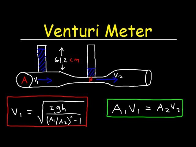
The formula for the Venturi flowmeter is based on the principle of conservation of mass and energy. It states that the flow rate of a fluid through a Venturi tube can be calculated using the following equation: Q = A1 sqrt(2 g h), where Q is the flow rate, A1 is the cross-sectional area of the inlet, g is the acceleration due to gravity, and h is the pressure differential between the inlet and throat of the Venturi tube.
Introduction to Venturi Flowmeters
Venturi flowmeters are flow measurement devices that use a constricted section to create a pressure differential. This pressure differential is then used to calculate the flow rate of the fluid. The formula for the Venturi flowmeter is based on the principle of conservation of mass and energy. The key components of a Venturi flowmeter include:
- Inlet: The section where the fluid enters the Venturi tube
- Throat: The constricted section where the pressure differential is created
- Exit: The section where the fluid exits the Venturi tube
Working Principle of Venturi Flowmeters
The working principle of Venturi flowmeters is based on the Bernoulli's principle, which states that the pressure of a fluid decreases as its velocity increases. As the fluid flows through the constricted section, its velocity increases, and its pressure decreases. This pressure differential is then used to calculate the flow rate of the fluid. The formula for the Venturi flowmeter takes into account the density of the fluid, the viscosity of the fluid, and the geometry of the Venturi tube. The key factors that affect the accuracy of the Venturi flowmeter include:
- Fluid properties: The density and viscosity of the fluid
- Venturi geometry: The shape and size of the Venturi tube
- Flow conditions: The flow rate and pressure of the fluid
Advantages of Venturi Flowmeters
Venturi flowmeters have several advantages over other types of flow measurement devices. They are highly accurate, reliable, and durable. They are also low maintenance and easy to install. The formula for the Venturi flowmeter is based on the principle of conservation of mass and energy, which makes it a theoretical and accurate device. The key benefits of using Venturi flowmeters include:
- High accuracy: Venturi flowmeters are highly accurate and reliable
- Low maintenance: Venturi flowmeters are low maintenance and easy to install
- Durability: Venturi flowmeters are durable and can withstand high pressure and high temperature
Applications of Venturi Flowmeters
Venturi flowmeters are widely used in various industries, including oil and gas, chemical processing, and power generation. They are used to measure the flow rate of liquids, gases, and steams. The formula for the Venturi flowmeter is used to calculate the flow rate of the fluid, which is then used to control and optimize the process. The key applications of Venturi flowmeters include:
- Flow measurement: Venturi flowmeters are used to measure the flow rate of fluids
- Process control: Venturi flowmeters are used to control and optimize the process
- Leak detection: Venturi flowmeters are used to detect leaks in the system
Limitations of Venturi Flowmeters
Venturi flowmeters have several limitations, including high cost, complex installation, and limited rangeability. They are also sensitive to fluid properties and flow conditions. The formula for the Venturi flowmeter is based on the principle of conservation of mass and energy, which makes it a theoretical and accurate device. However, the practical application of the formula is limited by the complexity of the flow and the geometry of the Venturi tube. The key limitations of Venturi flowmeters include:
- High cost: Venturi flowmeters are expensive to purchase and install
- Complex installation: Venturi flowmeters require complex installation and calibration
- Limited rangeability: Venturi flowmeters have limited rangeability and are sensitive to fluid properties and!flow conditions
What is the formula for flow rate through nozzle?
The formula for flow rate through a nozzle is given by the equation: Q = A √(2 ΔP / ρ), where Q is the flow rate, A is the cross-sectional area of the nozzle, ΔP is the pressure difference across the nozzle, and ρ is the density of the fluid. This equation is derived from the Bernoulli's principle and is commonly used to calculate the flow rate of fluids through nozzles in various engineering applications.
Derivation of the Formula
The derivation of the formula for flow rate through a nozzle involves the application of conservation of mass and conservation of energy principles. The flow rate through a nozzle can be calculated by considering the mass flow rate and the velocity of the fluid at the inlet and outlet of the nozzle. The formula can be derived as follows:
- The mass flow rate is given by the product of the density and velocity of the fluid.
- The velocity of the fluid at the outlet of the nozzle can be calculated using the Bernoulli's principle, which states that the sum of the kinetic energy and potential energy of a fluid remains constant along a streamline.
- The pressure difference across the nozzle is related to the velocity of the fluid at the outlet of the nozzle through the Bernoulli's equation.
Assumptions and Limitations
The formula for flow rate through a nozzle is based on several assumptions and has some limitations. The assumptions include:
- The fluid is incompressible, meaning that its density remains constant throughout the flow.
- The flow is steady, meaning that the velocity and pressure of the fluid at a given point do not change with time.
- The flow is one-dimensional, meaning that the velocity of the fluid is uniform across the cross-sectional area of the nozzle.
These assumptions are not always valid, and the formula may not accurately predict the flow rate through a nozzle in all situations.
Applications of the Formula
The formula for flow rate through a nozzle has several practical applications in engineering, including:
- Design of pipelines: The formula can be used to calculate the flow rate of fluids through pipelines and to design the pipeline system to meet the required flow rate.
- Design of pumps: The formula can be used to calculate the flow rate of fluids through pumps and to design the pump system to meet the required flow rate.
- Design of turbines: The formula can be used to calculate the flow rate of fluids through turbines and to design the turbine system to meet the required flow rate.
These applications require a thorough understanding of the fluid dynamics and thermodynamics involved in the flow of fluids through nozzles.
Experimental Verification
The formula for flow rate through a nozzle can be experimentally verified using various experimental techniques, including:
- Flow measurement: The flow rate of a fluid through a nozzle can be measured using a flow meter or other flow measurement devices.
- Pressure measurement: The pressure difference across the nozzle can be measured using pressure sensors or other pressure measurement devices.
- Velocity measurement: The velocity of the fluid at the outlet of the nozzle can be measured using velocity sensors or other velocity measurement devices.
These experimental techniques can be used to verify the accuracy of the formula and to determine the uncertainty associated with the measurements.
Numerical Solution
The formula for flow rate through a nozzle can be numerically solved using various numerical methods, including:
- Finite difference method: The finite difference method can be used to numerically solve the governing equations of the flow, including the continuity equation and the momentum equation.
- Finite element method: The finite element method can be used to numerically solve the governing equations of the flow, including the continuity equation and the momentum equation.
- Computational fluid dynamics: Computational fluid dynamics can be used to numerically solve the governing equations of the flow, including the continuity equation and the momentum equation, and to simulate the fluid flow through the nozzle.
These numerical methods can be used to solve the nonlinear equations involved in the flow of fluids through nozzles and to predict the flow rate and other flow parameters with high accuracy.
What is the formula for flowmeter?

The formula for a flowmeter is based on the principle of measuring the flow rate of a fluid, which is typically expressed in terms of volume flow rate (Q) or mass flow rate (m). The most common formula for flowmeter is Q = A v, where Q is the volume flow rate, A is the cross-sectional area of the pipe, and v is the average velocity of the fluid.
Basic Principles of Flowmeters
The basic principle of a flowmeter is to measure the flow rate of a fluid by detecting the pressure drop or velocity of the fluid as it passes through a restricted area. This can be achieved using various techniques, such as differential pressure, velocity, or ultrasonic measurements. The choice of flowmeter depends on the application, fluid properties, and required accuracy. Some common types of flowmeters include:
- Orifice plates: measure flow rate by detecting the pressure drop across a restricted area
- Venturi tubes: measure flow rate by detecting the pressure drop across a constricted section
- Turbine flowmeters: measure flow rate by detecting the rotation of a turbine wheel
Types of Flowmeters
There are several types of flowmeters, each with its own advantages and disadvantages. The choice of flowmeter depends on the application, fluid properties, and required accuracy. Some common types of flowmeters include differential pressure flowmeters, velocity flowmeters, and mass flowmeters. Differential pressure flowmeters are commonly used in oil and gas applications, while velocity flowmeters are commonly used in water treatment applications. Some common types of flowmeters include:
- Magnetic flowmeters: measure flow rate by detecting the electromagnetic field generated by the flowing fluid
- Ultrasonic flowmeters: measure flow rate by detecting the ultrasonic waves generated by the flowing fluid
- Coriolis flowmeters: measure flow rate by detecting the Coriolis force generated by the flowing fluid
Flowmeter Calibration
Calibration is an essential step in ensuring the accuracy of a flowmeter. The calibration process involves verifying the flow rate measurements against a reference standard. This can be done using a calibration laboratory or a portable calibration device. The calibration process typically involves:
- Zero-point calibration: verifying the flowmeter's zero-point measurement
- Span calibration: verifying the flowmeter's span measurement
- Linearity calibration: verifying the flowmeter's linearity measurement
Flowmeter Installation
The installation of a flowmeter is critical to ensuring accurate and reliable measurements. The flowmeter should be installed in a straight section of pipe, with a minimum straight length of pipe upstream and downstream of the flowmeter. The flowmeter should also be installed in a location that is accessible for maintenance and calibration. Some common installation considerations include:
- Pipe size and material
- Flowmeter orientation and positioning
- Upstream and downstream piping
Flowmeter Maintenance
Maintenance is essential to ensuring the accuracy and reliability of a flowmeter. The maintenance process typically involves cleaning, inspecting, and calibrating the flowmeter on a regular basis. The maintenance frequency depends on the application, fluid properties, and required accuracy. Some common maintenance activities include:
- Cleaning the flowmeter's sensing elements
- Inspecting the flowmeter's mechanical components
- Calibrating the flowmeter's measurements
Frequently Asked Questions (FAQs)
What is the principle behind the Nozzle Venturi and Orifice Flowmeter Formula and Calculator?
The Nozzle Venturi and Orifice Flowmeter is a device used to measure the flow rate of a fluid in a pipe. The principle behind this device is based on the Bernoulli's principle, which states that the pressure of a fluid decreases as its velocity increases. The Nozzle Venturi and Orifice Flowmeter uses a constriction in the pipe to increase the velocity of the fluid, which in turn decreases the pressure. By measuring the differential pressure across the constriction, the flow rate of the fluid can be calculated. The formula used to calculate the flow rate is based on the equation of continuity and the Bernoulli's equation, which take into account the density and viscosity of the fluid, as well as the geometry of the flowmeter. The calculator is a tool used to simplify the calculation process and provide accurate results.
How does the Nozzle Venturi and Orifice Flowmeter Formula and Calculator work?
The Nozzle Venturi and Orifice Flowmeter Formula and Calculator work by using the differential pressure measured across the constriction to calculate the flow rate of the fluid. The formula is based on the equation of continuity, which states that the mass flow rate of a fluid is constant throughout a pipe, and the Bernoulli's equation, which relates the pressure and velocity of a fluid. The calculator takes into account the geometry of the flowmeter, including the diameter and length of the constriction, as well as the properties of the fluid, such as its density and viscosity. By inputting the measured differential pressure and the geometry and properties of the flowmeter and fluid, the calculator can provide an accurate calculation of the flow rate. The formula and calculator can be used for a variety of applications, including liquid and gas flow measurement, and can be used in a range of industries, including chemical processing, oil and gas, and power generation.
What are the advantages of using the Nozzle Venturi and Orifice Flowmeter Formula and Calculator?
The Nozzle Venturi and Orifice Flowmeter Formula and Calculator offer several advantages over other methods of flow measurement. One of the main advantages is its high accuracy, which is due to the precise calculation of the flow rate based on the differential pressure and geometry of the flowmeter. Another advantage is its simplicity, as the formula and calculator are relatively easy to use and require minimal training and expertise. The Nozzle Venturi and Orifice Flowmeter is also a cost-effective solution, as it is often less expensive than other types of flowmeters, such as turbine or ultrasonic flowmeters. Additionally, the formula and calculator can be used for a wide range of applications, including low and high flow rates, and can be used with a variety of fluids, including liquids and gases. The Nozzle Venturi and Orifice Flowmeter is also a reliable and durable solution, as it is less prone to wear and tear than other types of flowmeters.
How can the Nozzle Venturi and Orifice Flowmeter Formula and Calculator be applied in real-world applications?
The Nozzle Venturi and Orifice Flowmeter Formula and Calculator can be applied in a wide range of real-world applications, including chemical processing, oil and gas, power generation, and water treatment. In chemical processing, the Nozzle Venturi and Orifice Flowmeter can be used to measure the flow rate of reactants and products, allowing for precise control of the chemical reaction. In oil and gas, the Nozzle Venturi and Orifice Flowmeter can be used to measure the flow rate of crude oil and natural gas, allowing for accurate measurement of production and transportation. In power generation, the Nozzle Venturi and Orifice Flowmeter can be used to measure the flow rate of steam and water, allowing for efficient operation of turbines and boilers. The Nozzle Venturi and Orifice Flowmeter can also be used in water treatment to measure the flow rate of water and wastewater, allowing for precise control of treatment processes. The formula and calculator can be used to design and optimize flow measurement systems, and can be used to troubleshoot and maintain existing systems.
Deja una respuesta
Entradas Relacionadas