
Hole Maximum Material Condition MMC vs Internal Feature Size Tolerance Chart Tool Calculator

The Hole Maximum Material Condition (MMC) vs Internal Feature Size Tolerance Chart Tool Calculator is a crucial resource for engineers and manufacturers. It helps determine the maximum allowable size of a hole or internal feature, considering the tolerance specifications. This calculator ensures that parts are manufactured within acceptable limits, reducing errors and improving overall quality. By utilizing this tool, users can efficiently calculate the MMC and verify compliance with design requirements, resulting in increased precision and reliability in various industries, including aerospace, automotive, and medical devices. Accurate calculations are essential for successful product development and production.
-
Hole Maximum Material Condition MMC vs Internal Feature Size Tolerance Chart Tool Calculator
- Understanding Hole Maximum Material Condition MMC
- Internal Feature Size Tolerance Chart Tool Calculator
- Benefits of Using the Hole Maximum Material Condition MMC
- How to Use the Internal Feature Size Tolerance Chart Tool Calculator
- Common Applications of the Hole Maximum Material Condition MMC and Internal Feature Size Tolerance Chart Tool Calculator
- How to calculate maximum material condition tolerance?
- How to calculate hole position tolerance?
-
Frequently Asked Questions (FAQs)
- What is the purpose of the Hole Maximum Material Condition (MMC) vs Internal Feature Size Tolerance Chart Tool Calculator?
- How does the Hole Maximum Material Condition (MMC) vs Internal Feature Size Tolerance Chart Tool Calculator work?
- What are the benefits of using the Hole Maximum Material Condition (MMC) vs Internal Feature Size Tolerance Chart Tool Calculator?
- How can the Hole Maximum Material Condition (MMC) vs Internal Feature Size Tolerance Chart Tool Calculator be applied in real-world scenarios?
Hole Maximum Material Condition MMC vs Internal Feature Size Tolerance Chart Tool Calculator
The Hole Maximum Material Condition (MMC) and Internal Feature Size Tolerance Chart Tool Calculator are essential tools in the field of engineering and manufacturing. The MMC refers to the maximum allowable size of a hole or a cavity in a part, while the Internal Feature Size Tolerance Chart Tool Calculator is a software or table used to determine the tolerances and limits of internal features such as holes, grooves, and pockets.
Understanding Hole Maximum Material Condition MMC
The MMC is a critical concept in geometric dimensioning and tolerancing (GD&T). It represents the maximum size of a hole or a cavity that can be produced while still meeting the design requirements. The MMC is typically specified on a drawing or in a specification, and it is used to ensure that the part is not too large or too small. The MMC is often used in conjunction with the Least Material Condition (LMC), which is the minimum size of a hole or a cavity.
Internal Feature Size Tolerance Chart Tool Calculator
The Internal Feature Size Tolerance Chart Tool Calculator is a software or table that is used to determine the tolerances and limits of internal features such as holes, grooves, and pockets. The calculator takes into account the MMC, LMC, and other factors such as the material and manufacturing process to determine the allowable tolerances and limits. The calculator is an essential tool for engineers and manufacturers, as it helps to ensure that parts are produced to the correct specifications.
Benefits of Using the Hole Maximum Material Condition MMC
The use of the MMC offers several benefits, including:
| Benefit | Description |
|---|---|
| Improved Accuracy | The MMC ensures that parts are produced to the correct size, reducing the risk of errors and defects. |
| Increased Efficiency | The MMC helps to streamline the manufacturing process, reducing the need for rework and scrap. |
| Cost Savings | The MMC can help to reduce costs by minimizing the amount of material used and reducing the need for expensive rework. |
How to Use the Internal Feature Size Tolerance Chart Tool Calculator
To use the Internal Feature Size Tolerance Chart Tool Calculator, follow these steps:
- Enter the MMC and LMC values for the internal feature.
- Select the material and manufacturing process.
- Enter the tolerance values for the internal feature.
- Click the calculate button to determine the allowable tolerances and limits.
Common Applications of the Hole Maximum Material Condition MMC and Internal Feature Size Tolerance Chart Tool Calculator
The MMC and Internal Feature Size Tolerance Chart Tool Calculator have a wide range of applications in industries such as aerospace, automotive, and medical devices. They are used to ensure that parts are produced to the correct specifications, reducing the risk of errors and defects. The MMC and calculator are also used to optimize the design and manufacturing process, reducing costs and improving efficiency. Some common applications include:
| Application | Description |
|---|---|
| Engine Components | The MMC and calculator are used to ensure that engine components such as cylinders and pistons are produced to the correct size and tolerance. |
| Aerospace Components | The MMC and calculator are used to ensure that aerospace components such as wings and fuselages are produced to the correct size and tolerance. |
How to calculate maximum material condition tolerance?
To calculate the maximum material condition (MMC) tolerance, you need to understand the concept of geometric dimensioning and tolerancing (GD&T). The MMC is the condition where the feature is at its maximum permissible size. The tolerance is the allowable variation in the size or position of a feature. The MMC tolerance is calculated by subtracting the minimum material condition (MMC) size from the maximum material condition (MMC) size.
Understanding Geometric Dimensioning and Tolerancing
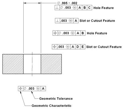
To calculate the MMC tolerance, you need to understand the principles of geometric dimensioning and tolerancing (GD&T). This involves understanding the symbols, notations, and rules used to specify tolerances. The key concepts include datum features, datum targets, and tolerance zones. The tolerance is specified using a tolerance value, which is the allowable variation in the size or position of a feature. Some key points to consider include:
- Datum features are the reference points for measuring tolerances.
- Tolerance zones define the allowable variation in the size or position of a feature.
- Geometric tolerances specify the allowable variation in the shape or orientation of a feature.
Calculating Maximum Material Condition Size
To calculate the MMC size, you need to determine the maximum permissible size of the feature. This involves analyzing the design and manufacturing requirements of the part. The MMC size is typically specified on the engineering drawing or in the design specifications. Some key points to consider include:
- Design specifications define the required size and tolerance of the feature.
- Manufacturing capabilities influence the achievable size and tolerance of the feature.
- Inspection methods affect the measurement uncertainty and tolerance of the feature.
Determining Minimum Material Condition Size
To calculate the MMC tolerance, you also need to determine the minimum material condition (MMC) size. The MMC size is the smallest permissible size of the feature. This involves analyzing the design and manufacturing requirements of the part. The MMC size is typically specified on the engineering drawing or in the design specifications. Some key points to consider include:
- Material properties affect the minimum size of the feature.
- Structural integrity requires a minimum size to ensure safety and performance.
- Functional requirements dictate the minimum size of the feature.
Applying Tolerance Calculations
To apply the tolerance calculations, you need to understand the mathematical formulas and rules used to calculate the tolerance. The tolerance is typically calculated using the plus/minus (±) notation, which specifies the allowable variation in the size or position of a feature. Some key points to consider include:
- Tolerance formulas provide a mathematical basis for calculating tolerances.
- Tolerance stacks analyze the cumulative effect of tolerances on the assembly.
- Sensitivity analysis evaluates the impact of tolerance variations on the design.
Verifying Tolerance Specifications
To verify the tolerance specifications, you need to ensure that the tolerance values are correct and consistent with the design and manufacturing requirements. This involves reviewing the engineering drawing and design specifications to ensure that the tolerance values are accurate and complete. Some key points to consider include:
- Tolerance verification ensures that the tolerance values are correct and consistent.
- Design review evaluates the design and manufacturing requirements to ensure that the tolerance values are adequate.
- Manufacturing review assesses the manufacturing capabilities to ensure that the tolerance values are achievable.
How to calculate hole position tolerance?
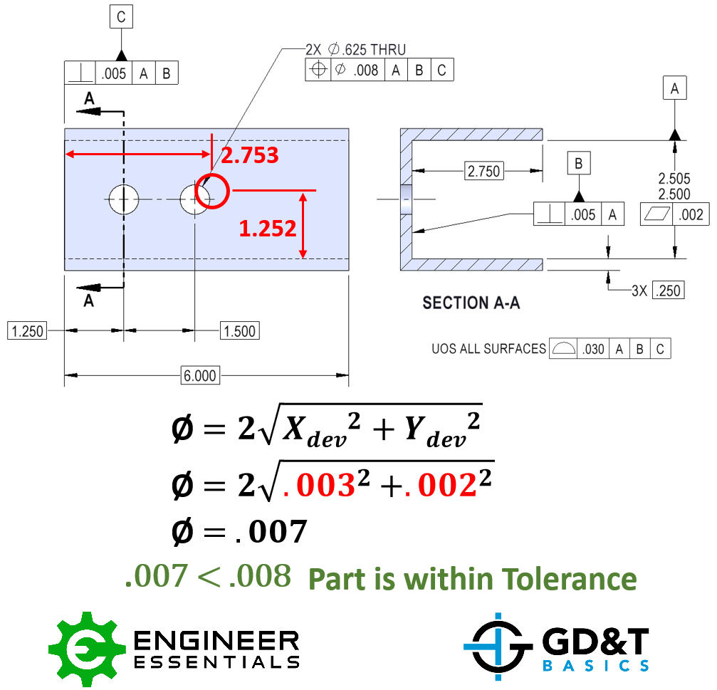
To calculate hole position tolerance, you need to consider the geometric dimensioning and tolerancing (GD&T) principles. The position tolerance of a hole is the allowable variation in the location of the hole's center. The calculation involves determining the datum reference frames, tolerance zones, and bonus tolerance. The position tolerance is typically specified as a diameter or radius value, and it can be affected by datum shifts and tolerance stacks.
Understanding Geometric Dimensioning and Tolerancing (GD&T)
Geometric dimensioning and tolerancing (GD&T) is a standardized system for defining and communicating the tolerances and dimensions of parts and assemblies. To calculate the hole position tolerance, you need to understand the GD&T principles, including the datum reference frames, tolerance zones, and bonus tolerance. The key points to consider are:
- Datum features: Identify the datum features that are used to establish the datum reference frames.
- Tolerance zones: Determine the tolerance zones for the hole position, which define the allowable variation in the location of the hole's center.
- Bonus tolerance: Apply the bonus tolerance rules to calculate the total tolerance for the hole position.
Determining Datum Reference Frames
The datum reference frames are the coordinate systems used to define the position and orientation of the hole. To determine the datum reference frames, you need to identify the primary, secondary, and tertiary datums. The key points to consider are:
- Primary datum: Identify the primary datum, which is the main reference frame for the hole position.
- Secondary datum: Determine the secondary datum, which is used to constrain the hole position.
- Tertiary datum: Apply the tertiary datum to fully constrain the hole position.
Calculating Tolerance Zones
The tolerance zones define the allowable variation in the hole position. To calculate the tolerance zones, you need to apply the GD&T rules and consider the datum shifts and tolerance stacks. The key points to consider are:
- Tolerance value: Specify the tolerance value, which defines the allowable variation in the hole position.
- Datum shifts: Apply the datum shifts to calculate the effective tolerance zone.
- Tolerance stacks: Consider the tolerance stacks to ensure that the total tolerance is within the specified limits.
Applying Bonus Tolerance
The bonus tolerance is an additional tolerance that can be applied to the hole position. To apply the bonus tolerance, you need to consider the GD&T rules and the datum reference frames. The key points to consider are:
- Bonus tolerance value: Specify the bonus tolerance value, which defines the additional allowable variation in the hole position.
- Datum reference frames: Apply the bonus tolerance to the datum reference frames to calculate the total tolerance.
- Tolerance stacks: Consider the tolerance stacks to ensure that the total tolerance is within the specified limits.
Verifying Tolerance Compliance
To verify that the hole position is within the specified tolerance, you need to measure the position of the hole and compare it to the specified tolerance zone. The key points to consider are:
- Measurement method: Choose a measurement method that is accurate and reliable.
- Tolerance zone calculation: Calculate the tolerance zone using the GD&T rules and the datum reference frames.
- Compliance check: Compare the measured position of the hole to the specified tolerance zone to verify compliance.
Frequently Asked Questions (FAQs)
What is the purpose of the Hole Maximum Material Condition (MMC) vs Internal Feature Size Tolerance Chart Tool Calculator?
The Hole Maximum Material Condition (MMC) vs Internal Feature Size Tolerance Chart Tool Calculator is a design tool used to calculate the maximum allowable size of a hole or internal feature in a part, based on its tolerance and material condition. This calculator is essential in engineering and manufacturing to ensure that the design specifications are met, and the part functions as intended. By using this calculator, designers and engineers can determine the optimum size of the hole or internal feature, taking into account the tolerance and material condition, to ensure proper fit and functionality. The calculator also helps to prevent errors and ensure precision in the design and manufacturing process.
How does the Hole Maximum Material Condition (MMC) vs Internal Feature Size Tolerance Chart Tool Calculator work?
The Hole Maximum Material Condition (MMC) vs Internal Feature Size Tolerance Chart Tool Calculator works by inputting the nominal size of the hole or internal feature, the tolerance, and the material condition. The calculator then uses complex algorithms and geometric calculations to determine the maximum allowable size of the hole or internal feature. The calculator takes into account various factors, such as the type of tolerance, datum features, and material conditions, to provide an accurate calculation. The result is a precise value that represents the maximum size of the hole or internal feature, ensuring proper fit and functionality. The calculator also provides additional information, such as tolerance zones and limit dimensions, to help designers and engineers make informed decisions.
What are the benefits of using the Hole Maximum Material Condition (MMC) vs Internal Feature Size Tolerance Chart Tool Calculator?
The benefits of using the Hole Maximum Material Condition (MMC) vs Internal Feature Size Tolerance Chart Tool Calculator are numerous. One of the primary benefits is increased precision, as the calculator provides accurate calculations that take into account various factors and tolerances. This ensures that the design specifications are met, and the part functions as intended. Another benefit is reduced errors, as the calculator helps to prevent mistakes and ensure accuracy in the design and manufacturing process. Additionally, the calculator saves time and increases efficiency, as it provides quick and accurate calculations, allowing designers and engineers to focus on other aspects of the design and manufacturing process. The calculator also improves communication between designers, engineers, and manufacturers, as it provides a common language and standardized calculations.
How can the Hole Maximum Material Condition (MMC) vs Internal Feature Size Tolerance Chart Tool Calculator be applied in real-world scenarios?
The Hole Maximum Material Condition (MMC) vs Internal Feature Size Tolerance Chart Tool Calculator can be applied in various real-world scenarios, such as aerospace engineering, automotive manufacturing, and medical device design. In these industries, precise calculations and accurate tolerances are critical to ensure proper fit and functionality of parts. The calculator can be used to design and manufacture complex components, such as engine parts, gearboxes, and implants. Additionally, the calculator can be used to analyze and optimize existing designs, reducing errors and improving performance. The calculator can also be used in quality control and inspection processes to verify and validate the dimensions and tolerances of parts, ensuring that they meet industry standards and regulations. By applying the calculator in these scenarios, designers and engineers can ensure precision, reduce errors, and improve overall performance.
Deja una respuesta
Entradas Relacionadas