
Head Loss Fluid Across Screen Equation and Calculator

The head loss of fluid across a screen is a critical factor in various engineering applications, including water treatment, filtration systems, and hydraulic design. Head loss refers to the reduction in pressure or energy of a fluid as it flows through a screen or mesh. The equation for calculating head loss across a screen takes into account factors such as screen mesh size, fluid velocity, and viscosity. This article provides an overview of the head loss fluid across screen equation and offers a calculator to help engineers and designers estimate head loss in their systems. Accurate calculations are essential.
- Head Loss Fluid Across Screen Equation and Calculator
- What is the formula for head loss in screening?
- What is the formula for head loss?
- How to calculate head loss in horizontal pipe?
- How do you calculate pressure drop from head loss?
-
Frequently Asked Questions (FAQs)
- What is the Head Loss Fluid Across Screen Equation and how is it used in engineering applications?
- How does the Head Loss Fluid Across Screen Equation account for the effects of screen mesh size and thickness on fluid flow?
- What are some common applications of the Head Loss Fluid Across Screen Equation in industrial processes?
- How can the Head Loss Fluid Across Screen Equation be used to optimize fluid flow systems and reduce energy consumption?
Head Loss Fluid Across Screen Equation and Calculator
The head loss fluid across screen equation and calculator are essential tools for determining the pressure drop that occurs when a fluid flows through a screen or mesh. This pressure drop, also known as head loss, is a critical factor in the design and operation of various systems, including water treatment plants, chemical processing facilities, and power generation stations. The equation and calculator used to determine head loss fluid across screen take into account several factors, including the velocity of the fluid, the density of the fluid, the mesh size of the screen, and the thickness of the screen.
Introduction to Head Loss Fluid Across Screen Equation
The head loss fluid across screen equation is based on the Darcy-Weisbach equation, which is a widely used formula for calculating the pressure drop in a pipe or conduit. However, the equation for head loss fluid across screen is modified to account for the unique characteristics of a screen or mesh. The equation is as follows: ΔP = (K ρ V^2) / (2 g), where ΔP is the pressure drop, K is a constant that depends on the mesh size and thickness of the screen, ρ is the density of the fluid, V is the velocity of the fluid, and g is the acceleration due to gravity.
Factors Affecting Head Loss Fluid Across Screen
There are several factors that affect the head loss fluid across screen, including the mesh size of the screen, the thickness of the screen, the velocity of the fluid, and the density of the fluid. The mesh size of the screen affects the pressure drop by altering the flow path of the fluid, while the thickness of the screen affects the pressure drop by increasing the resistance to flow. The velocity of the fluid also affects the pressure drop, as higher velocities result in greater pressure drops.
Head Loss Fluid Across Screen Calculator
A head loss fluid across screen calculator is a tool used to determine the pressure drop that occurs when a fluid flows through a screen or mesh. The calculator uses the equation mentioned earlier and takes into account the various factors that affect the pressure drop. The calculator is typically used in the design and operation of systems that involve the flow of fluids through screens or meshes, such as water treatment plants and chemical processing facilities.
Applications of Head Loss Fluid Across Screen Equation and Calculator
The head loss fluid across screen equation and calculator have a wide range of applications in various fields, including water treatment, chemical processing, and power generation. In water treatment plants, the equation and calculator are used to design and operate systems that involve the flow of water through screens or meshes, such as intake screens and filter screens. In chemical processing facilities, the equation and calculator are used to design and operate systems that involve the flow of chemicals through screens or meshes, such as catalyst screens and filter screens.
Limitations and Assumptions of Head Loss Fluid Across Screen Equation and Calculator
The head loss fluid across screen equation and calculator have several limitations and assumptions that must be considered when using them. One limitation is that the equation and calculator assume a steady-state flow, which may not always be the case in real-world applications. Another limitation is that the equation and calculator assume a fully turbulent flow, which may not always be the case in real-world applications. The following table summarizes some of the key factors that affect the head loss fluid across screen:
| Factor | Description |
|---|---|
| Mesh size | Affects the flow path of the fluid |
| Thickness | Affects the resistance to flow |
| Velocity | Affects the pressure drop |
| Density | Affects the pressure drop |
What is the formula for head loss in screening?
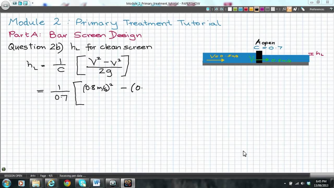
The formula for head loss in screening is given by the equation: hf = (K × v^2) / (2 × g), where hf is the head loss, K is a dimensionless coefficient, v is the velocity of the fluid, and g is the acceleration due to gravity. This equation is commonly used to calculate the energy losses that occur in a fluid as it flows through a screen or a mesh.
Introduction to Head Loss in Screening
Head loss in screening is an important consideration in the design of water treatment and wastewater treatment systems. The head loss that occurs as water flows through a screen or a mesh can have a significant impact on the overall efficiency of the system. In order to minimize head loss and optimize system performance, it is essential to understand the factors that influence head loss and to use the correct equation to calculate it. Some of the key factors that influence head loss include the velocity of the fluid, the size and shape of the screen or mesh, and the properties of the fluid itself. These factors can be summarized as follows:
- Velocity of the fluid: The velocity of the fluid has a significant impact on head loss, with higher velocities resulting in greater head loss.
- Size and shape of the screen or mesh: The size and shape of the screen or mesh can also affect head loss, with smaller openings and more complex shapes resulting in greater head loss.
- Properties of the fluid: The properties of the fluid, such as its viscosity and density, can also influence head loss, with more viscous fluids resulting in greater head loss.
Factors Affecting Head Loss in Screening
There are several factors that can affect head loss in screening, including the velocity of the fluid, the size and shape of the screen or mesh, and the properties of the fluid itself. The velocity of the fluid is one of the most important factors, as it has a direct impact on the energy losses that occur as the fluid flows through the screen or mesh. The size and shape of the screen or mesh can also affect head loss, with smaller openings and more complex shapes resulting in greater head loss. Additionally, the properties of the fluid, such as its viscosity and density, can also influence head loss. The key factors that affect head loss can be summarized as follows:
- Screen or mesh size: The size of the screen or mesh can have a significant impact on head loss, with smaller openings resulting in greater head loss.
- Screen or mesh shape: The shape of the screen or mesh can also affect head loss, with more complex shapes resulting in greater head loss.
- Fluid viscosity: The viscosity of the fluid can also influence head loss, with more viscous fluids resulting in greater head loss.
Calculating Head Loss in Screening
Calculating head loss in screening is a critical step in the design of water treatment and wastewater treatment systems. The equation for head loss, hf = (K × v^2) / (2 × g), can be used to calculate the energy losses that occur as water flows through a screen or a mesh. To use this equation, it is necessary to know the velocity of the fluid, the dimensionless coefficient K, and the acceleration due to gravity. The dimensionless coefficient K can be determined using experimental data or by consulting a reference source. The key steps in calculating head loss can be summarized as follows:
- Determine the velocity of the fluid: The velocity of the fluid must be determined in order to calculate head loss.
- Determine the dimensionless coefficient K: The dimensionless coefficient K must be determined using experimental data or by consulting a reference source.
- Calculate head loss: Once the velocity and dimensionless coefficient K are known, head loss can be calculated using the equation hf = (K × v^2) / (2 × g).
Minimizing Head Loss in Screening
Minimizing head loss in screening is essential in order to optimize the performance of water treatment and wastewater treatment systems. There are several strategies that can be used to minimize head loss, including using screens or meshes with larger openings, using screens or meshes with simpler shapes, and using fluids with lower viscosity. Additionally, the velocity of the fluid can be reduced in order to minimize head loss. The key strategies for minimizing head loss can be summarized as follows:
- Use screens or meshes with larger openings: Using screens or meshes with larger openings can help to minimize head loss.
- Use screens or meshes with simpler shapes: Using screens or meshes with simpler shapes can also help to minimize head loss.
- Use fluids with lower viscosity: Using fluids with lower viscosity can help to minimize head loss.
Applications of Head Loss in Screening
Head loss in screening has a number of important applications in the design of water treatment and wastewater treatment systems. The equation for head loss, hf = (K × v^2) / (2 × g), can be used to calculate the energy losses that occur as water flows through a screen or a mesh. This information can be used to optimize the performance of the system and to minimize the energy required to pump the fluid. The key applications of head loss in screening can be summarized as follows:
- Water treatment systems: Head loss in screening is an important consideration in the design of water treatment systems.
- Wastewater treatment systems: Head loss in screening is also an important consideration in the design of wastewater treatment systems.
- Pumping systems: Head loss in screening can be used to optimize the performance of pumping systems and to minimize the energy required to pump the fluid.
What is the formula for head loss?
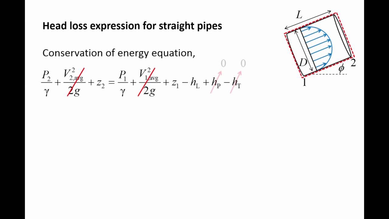
The formula for head loss is given by the Darcy-Weisbach equation, which states that the head loss due to friction in a pipe is proportional to the length of the pipe, the velocity of the fluid, and the roughness of the pipe, and inversely proportional to the diameter of the pipe and the gravity. The equation is as follows: h_f = f (L/D) (v^2 / (2 g)), where h_f is the head loss, f is the friction factor, L is the length of the pipe, D is the diameter of the pipe, v is the velocity of the fluid, and g is the acceleration due to gravity.
Factors Affecting Head Loss
The head loss in a pipe is affected by several factors, including the velocity of the fluid, the roughness of the pipe, and the length of the pipe. The following are some of the key factors that affect head loss:
- The velocity of the fluid: As the velocity of the fluid increases, the head loss also increases.
- The roughness of the pipe: The rougher the pipe, the greater the head loss.
- The length of the pipe: The longer the pipe, the greater the head loss.
Importance of Head Loss in Pipe Flow
Head loss is an important consideration in pipe flow because it affects the pressure and flow rate of the fluid. The head loss in a pipe can be significant, and it can affect the overall efficiency of the system. The following are some of the reasons why head loss is important:
- Pressure drop: Head loss can cause a significant drop in pressure, which can affect the flow rate of the fluid.
- Energy loss: Head loss can result in a significant loss of energy, which can affect the overall efficiency of the system.
- Pipe sizing: Head loss can affect the sizing of pipes, and it is an important consideration in the design of pipe systems.
Calculating Head Loss
Calculating head loss involves using the Darcy-Weisbach equation and the friction factor. The friction factor is a measure of the resistance to flow in a pipe, and it is affected by the Reynolds number and the roughness of the pipe. The following are the steps involved in calculating head loss:
- Determine the Reynolds number of the flow.
- Determine the friction factor using the Reynolds number and the roughness of the pipe.
- Use the Darcy-Weisbach equation to calculate the head loss.
Minimizing Head Loss
Minimizing head loss is important in pipe flow because it can help to improve the efficiency of the system. The following are some of the ways to minimize head loss:
- Use smooth pipes to reduce the friction factor.
- Use larger pipes to reduce the velocity of the fluid.
- Use pipe fittings and valves that are designed to minimize head loss.
Applications of Head Loss
Head loss has several applications in engineering and science. The following are some of the applications of head loss:
- Water supply systems: Head loss is an important consideration in the design of water supply systems.
- Wastewater systems: Head loss is also an important consideration in the design of wastewater systems.
- Industrial processes: Head loss is an important consideration in the design of industrial processes that involve fluid flow.
How to calculate head loss in horizontal pipe?

To calculate head loss in a horizontal pipe, you need to consider the frictional losses that occur due to the flow of fluid through the pipe. The head loss can be calculated using the Darcy-Weisbach equation, which takes into account the length of the pipe, the diameter of the pie, the friction factor, and the velocity of the fluid. The equation is given by: h_f = f (L/D) (v^2 / (2 g)), where h_f is the head loss, f is the friction factor, L is the length of the pipe, D is the diameter of the pipe, v is the velocity of the fluid, and g is the acceleration due to gravity.
Introduction to Head Loss Calculation
The calculation of head loss in a horizontal pipe is crucial in the design of pipeline systems. The head loss can be calculated using the Darcy-Weisbach equation, which is a widely used equation in the field of fluid mechanics. The equation takes into account the frictional losses that occur due to the flow of fluid through the pipe. Some of the key factors that affect the head loss are:
- Pipe diameter: The diameter of the pipe plays a significant role in the calculation of head loss. A smaller pipe diameter results in a higher head loss.
- Pipe length: The length of the pipe also affects the head loss. A longer pipe results in a higher head loss.
- Fluid velocity: The velocity of the fluid flowing through the pipe also affects the head loss. A higher fluid velocity results in a higher head loss.
Factors Affecting Head Loss
There are several factors that affect the head loss in a horizontal pipe. The friction factor is one of the most important factors, as it takes into account the roughness of the pipe and the Reynolds number of the flow. The friction factor can be calculated using the Colebrook-White equation, which is a widely used equation in the field of fluid mechanics. Some of the other factors that affect the head loss are:
- Pipe material: The material of the pipe can affect the head loss, as different materials have different roughness values.
- Fluid properties: The properties of the fluid, such as its viscosity and density, can also affect the head loss.
- Flow regime: The flow regime, whether it is laminar or turbulent, can also affect the head loss.
Equations Used in Head Loss Calculation
There are several equations that can be used to calculate the head loss in a horizontal pipe. The Darcy-Weisbach equation is one of the most widely used equations, as it takes into account the frictional losses that occur due to the flow of fluid through the pipe. The equation is given by: h_f = f (L/D) (v^2 / (2 g)), where h_f is the head loss, f is the friction factor, L is the length of the pipe, D is the diameter of the pipe, v is the velocity of the fluid, and g is the acceleration due to gravity. Some of the other equations that can be used are:
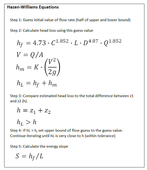
- Hazen-Williams equation: This equation is used to calculate the head loss in a horizontal pipe, and it is given by: h_f = (10.67 L (v^1.852) / (C^1.852 D^4.87)), where h_f is the head loss, L is the length of the pipe, v is the velocity of the fluid, C is the Hazen-Williams coefficient, and D is the diameter of the pipe.
- Manning equation: This equation is used to calculate the head loss in an open channel, and it is given by: h_f = (n^2 L v^2) / (R^4/3 S), where h_f is the head loss, n is the Manning's roughness coefficient, L is the length of the channel, v is the velocity of the fluid, R is the hydraulic radius, and S is the slope of the channel.
- Chezy equation: This equation is used to calculate the head loss in an open channel, and it is given by: h_f = (L v^2) / (2 g R C^2), where h_f is the head loss, L is the length of the channel, v is the velocity of the fluid, g is the acceleration due to gravity, R is the hydraulic radius, and C is the Chezy coefficient.
Applications of Head Loss Calculation
The calculation of head loss in a horizontal pipe has several practical applications. It is used in the design of pipeline systems, such as water supply systems, sewage systems, and gas transmission systems. The head loss calculation is also used in the design of pumping systems, such as water pumps and sewage pumps. Some of the other applications of head loss calculation are:
- Flow rate calculation: The head loss calculation can be used to calculate the flow rate of a fluid through a pipe.
- Pressure drop calculation: The head loss calculation can be used to calculate the pressure drop across a pipe.
- Energy loss calculation: The head loss calculation can be used to calculate the energy loss due to the flow of fluid through a pipe.
Challenges in Head Loss Calculation
There are several challenges associated with the calculation of head loss in a horizontal pipe. One of the main challenges is the accurate determination of the friction factor, which can be difficult to measure. Another challenge is the selection of the correct equation, as there are several equations that can be used to calculate the head loss. Some of the other challenges are:
- Uncertainty in pipe roughness: The roughness of the pipe can be uncertain, which can affect the accuracy of the head loss calculation.
- Uncertainty in fluid properties: The properties of the fluid, such as its viscosity and density, can be uncertain, which can affect the accuracy of the head loss calculation.
- Complex pipe geometries: The geometry of the pipe can be complex, which can make
How do you calculate pressure drop from head loss?
To calculate pressure drop from head loss, you can use the following formula: ΔP = ρ g h, where ΔP is the pressure drop, ρ is the density of the fluid, g is the acceleration due to gravity, and h is the head loss. This formula is based on the Bernoulli's principle, which states that the total energy of a fluid in a closed system remains constant.
Understanding Head Loss
Head loss is a critical factor in calculating pressure drop. It refers to the loss of energy in a fluid due to friction and other resistances in the pipeline or channel. The head loss can be calculated using the Darcy-Weisbach equation, which takes into account the length and diameter of the pipeline, as well as the roughness of the pipeline material. The key factors to consider when calculating head loss are:
- Fluid velocity: The velocity of the fluid flowing through the pipeline or channel.
- Pipeline material: The type of material used for the pipeline, which affects its roughness and friction.
- Pipeline diameter: The diameter of the pipeline, which affects the flow area and velocity of the fluid.
Calculating Pressure Drop
Calculating pressure drop from head loss requires a thorough understanding of the fluid properties and the pipeline characteristics. The pressure drop can be calculated using the formula: ΔP = ρ g h, where ΔP is the pressure drop, ρ is the density of the fluid, g is the acceleration due to gravity, and h is the head loss. The key factors to consider when calculating pressure drop are:
- Fluid density: The density of the fluid, which affects its weight and pressure.
- Acceleration due to gravity: The acceleration due to gravity, which affects the weight and pressure of the fluid.
- Head loss: The head loss calculated using the Darcy-Weisbach equation or other methods.
Factors Affecting Pressure Drop
Several factors can affect the pressure drop in a pipeline or channel, including fluid velocity, pipeline material, and pipeline diameter. The pressure drop can also be affected by valves, fittings, and other obstructions in the pipeline. The key factors to consider when evaluating the pressure drop are:
- Valve losses: The pressure drop caused by valves and other obstructions in the pipeline.
- Fitting losses: The pressure drop caused by fittings and other obstructions in the pipeline.
- Pipeline roughness: The roughness of the pipeline material, which affects friction and pressure drop.
Applications of Pressure Drop Calculation
Calculating pressure drop from head loss has several practical applications in various fields, including chemical engineering, mechanical engineering, and civil engineering. The pressure drop calculation can be used to design and optimize pipelines, pumps, and other fluid handling systems. The key applications of pressure drop calculation are:
- Pipeline design: The design of pipelines to minimize pressure drop and energy losses.
- Pump selection: The selection of pumps to match the pressure drop and flow rate requirements.
- System optimization: The optimization of fluid handling systems to minimize energy losses and costs.
Best Practices for Pressure Drop Calculation
To ensure accurate pressure drop calculations, it is essential to follow best practices, including using reliable data and valid assumptions. The pressure drop calculation should be based on a thorough understanding of the fluid properties and pipeline characteristics. The key best practices for pressure drop calculation are:
- Verify assumptions: Verify the assumptions made in the pressure drop calculation to ensure they are valid and reliable.
- Use reliable data: Use reliable data for the fluid properties and pipeline characteristics to ensure accurate pressure drop calculations.
- Consider all factors: Consider all the factors that can affect the pressure drop, including valves, fittings, and pipeline roughness.
Frequently Asked Questions (FAQs)
What is the Head Loss Fluid Across Screen Equation and how is it used in engineering applications?
The Head Loss Fluid Across Screen Equation is a mathematical model used to calculate the pressure drop or head loss that occurs when a fluid flows through a screen or a mesh. This equation is commonly used in various engineering applications, such as chemical engineering, mechanical engineering, and civil engineering, where fluids are pumped or flow through pipes, tanks, or other equipment. The equation takes into account the velocity of the fluid, the density of the fluid, the mesh size of the screen, and the thickness of the screen. By using this equation, engineers can predict and calculate the head loss that will occur in a particular system, which is essential for designing and optimizing fluid flow systems.
How does the Head Loss Fluid Across Screen Equation account for the effects of screen mesh size and thickness on fluid flow?
The Head Loss Fluid Across Screen Equation accounts for the effects of screen mesh size and thickness on fluid flow by incorporating these parameters into the mathematical model. The equation uses the mesh size and thickness to calculate the pressure drop or head loss that occurs as the fluid flows through the screen. The mesh size affects the turbulence and resistance to flow, while the thickness affects the length of the flow path and the amount of turbulence generated. By including these parameters in the equation, engineers can accurately predict the head loss that will occur in a particular system, taking into account the specific screen characteristics. This allows for the optimization of fluid flow systems and the selection of the most suitable screen or mesh for a particular application.
What are some common applications of the Head Loss Fluid Across Screen Equation in industrial processes?
The Head Loss Fluid Across Screen Equation has a wide range of industrial applications, including water treatment, chemical processing, oil and gas production, and power generation. In water treatment, the equation is used to design and optimize filter systems and screening systems to remove impurities and contaminants from water. In chemical processing, the equation is used to design and optimize reactors and separators to ensure efficient and safe operation. In oil and gas production, the equation is used to design and optimize well screens and perforated pipes to maximize fluid flow and hydrocarbon recovery. In power generation, the equation is used to design and optimize condenser systems and heat exchangers to ensure efficient and reliable operation.
How can the Head Loss Fluid Across Screen Equation be used to optimize fluid flow systems and reduce energy consumption?
The Head Loss Fluid Across Screen Equation can be used to optimize fluid flow systems and reduce energy consumption by minimizing the pressure drop or head loss that occurs in the system. By using the equation to predict and calculate the head loss that will occur in a particular system, engineers can identify areas where energy losses are occurring and optimize the system to reduce these losses. This can be achieved by selecting the most suitable screen or mesh for a particular application, designing the system to minimize turbulence and resistance to flow, and optimizing the operating conditions to reduce energy consumption. By reducing energy consumption, companies can lower their operating costs, reduce their environmental impact, and improve their competitiveness in the market.
Deja una respuesta
Entradas Relacionadas